Aerodynamic Analysis: Vortex Generator Effects on Light-Duty Vehicles
VerifiedAdded on 2021/06/22
|48
|14371
|427
Report
AI Summary
This report investigates the aerodynamic effects of vortex generators on light-duty vehicles, focusing on drag reduction and fuel efficiency. The study begins with an introduction to vortex generators, their background, research aims, objectives, and research questions. A comprehensive literature review covers empirical studies, models, and theories related to aerodynamics, including Bernoulli's principle and the Coanda effect, identifying gaps in existing research. The methodology section outlines the research approach, design, and methods, including the use of SolidWorks simulation to analyze the vortex generator's impact. The findings and analysis section presents 3D views, installation steps, and graphs comparing the coefficient of drag with and without vortex generators. Secondary analysis explores airflow, velocity profiles, and the behavior of vortex generators. Discussion of findings includes a created model under automotive aerodynamics and analysis of forces. The report concludes by linking findings with objectives and provides recommendations.
INVESTIGATION FOR THE EFFECTS OF THE VORTEX
GENERATOR OF THE LIGHT-DUTY VEHICLE
GENERATOR OF THE LIGHT-DUTY VEHICLE
Paraphrase This Document
Need a fresh take? Get an instant paraphrase of this document with our AI Paraphraser
Abstract
Here a model has to be created which is totally depends on the properties of the
aerodynamics. The main aim of this report is to creating the model of the automotive vehicle
in which the control over surface is needs to accomplished as well as the turbulence energy
of the vehicle as well as the drag force is needs to be determined. A vortex generator is a
control mechanism for aerodynamic drag that is present on the car's high specific surface
area. In airflow devices such as airlines and for automobiles, they are typically used. The
vortex generator generates a vortex as the airfoil moves relative to air, which slows the
isolation and aero deification of the stream and improves the efficiency of the wings as flaps,
elevators and rotors by replacing the slowly flowing flow separation in connection with the
surfaces. The main purpose of Vortex generators is to slow the flow of removing
contaminants on the moving object.
2
Table of Contents
1.0 Introduction................................................................................................................................4
1.1 Introduction............................................................................................................................4
1.2 Background............................................................................................................................4
1.3 Research Aim.........................................................................................................................5
1.4 Research objectives................................................................................................................5
1.5 Research Questions................................................................................................................5
1.6 Research Rationale.................................................................................................................6
1.7 Research significance.............................................................................................................6
1.8 Research Framework..............................................................................................................7
Figure 1: Conceptual framework..............................................................................................7
1.9 Conclusion.............................................................................................................................7
2.0 Literature Review......................................................................................................................7
2.1 Introduction............................................................................................................................7
2.2 Empirical Study......................................................................................................................9
Figure 2: The properties and mechanism of aerodynamic.....................................................11
Drag............................................................................................................................................12
2.3 Models and Theories............................................................................................................13
Bernoulli’s principle..................................................................................................................14
Coanda effect.............................................................................................................................14
2.6 Literature Gap......................................................................................................................15
2.7 Conclusion...........................................................................................................................15
3.0 Methodology............................................................................................................................17
3.1 Introduction..........................................................................................................................17
3
⊘ This is a preview!⊘
Do you want full access?
Subscribe today to unlock all pages.
Trusted by 1+ million students worldwide
3.2 Method Outline....................................................................................................................17
3.3 Research Onion....................................................................................................................18
Figure 3: Research onion........................................................................................................18
3.4 Research Approach..............................................................................................................18
3.5 Research Design...................................................................................................................19
3.6 Research Methods................................................................................................................19
3.7 Research Philosophy............................................................................................................19
3.7 Research Strategy.................................................................................................................20
3.8 Method of Data collection....................................................................................................20
3.9 Research Ethics....................................................................................................................20
3.10 Research Limitation...........................................................................................................21
3.11 Conclusion.........................................................................................................................21
4.0 Findings and Analysis..............................................................................................................21
4.1 Introduction..........................................................................................................................21
4.2 Analysis................................................................................................................................22
Figure 4: The vortex generator in 3D view with dimension..................................................22
Figure 5: Stapes for installing the vortex generator...............................................................23
Figure 6: "Reynolds number (Re) Vs. Coefficient of drag graph without vortex generator."
................................................................................................................................................25
Figure 7: "Reynolds number (Re) Vs. Coefficient of drag (Cd) graph with a vortex
generator."..............................................................................................................................26
Figure 8: “Comparison of Cd between with vortex and without vortex Genera-tor”............26
4.2.1 Secondary Analysis...........................................................................................................27
Figure 9: Airflow over the car................................................................................................28
Figure 10: Velocity profile at the roof of a car without VG...................................................28
Figure 11: Flow around Vortex generator.............................................................................29
4
Paraphrase This Document
Need a fresh take? Get an instant paraphrase of this document with our AI Paraphraser
4.3 Discussion of Findings.........................................................................................................29
Figure 12: The created model under the Automotive aerodynamics.....................................30
Figure 13: The act of force in the vehicle..............................................................................31
4.3.1 Secondary Analysis...........................................................................................................31
Figure 14: The RMS value of the vehicle..............................................................................32
Figure 15: Turbulence factor of the vehicle...........................................................................33
Figure 16: The final created model of the aerodynamics.......................................................34
4.4 Conclusion...........................................................................................................................34
5.0 Conclusion...............................................................................................................................34
5.1 Introduction..........................................................................................................................34
5.2 Linking with Objectives.......................................................................................................35
5.3 Recommendations................................................................................................................36
5.4 Conclusions..........................................................................................................................36
Reference List................................................................................................................................38
Appendix........................................................................................................................................44
5
Figure 1: Conceptual framework...................................................................................................10
Figure 2: The properties and mechanism of aerodynamic.............................................................14
Figure 3: Research onion...............................................................................................................21
Figure 4: The vortex generator in 3D view with dimension..........................................................25
Figure 5: Stapes for installing the vortex generator.......................................................................26
Figure 6: "Reynolds number (Re) Vs. Coefficient of drag graph without vortex generator.".......28
Figure 7: "Reynolds number (Re) Vs. Coefficient of drag (Cd) graph with a vortex generator.".29
Figure 8: “Comparison of Cd between with vortex and without vortex Genera-tor”...................29
Figure 9: Airflow over the car.......................................................................................................31
Figure 10: Velocity profile at the roof of a car without VG..........................................................31
Figure 11: Flow around Vortex generator....................................................................................32
Figure 12: The created model under the Automotive aerodynamics.............................................33
Figure 13: The act of force in the vehicle......................................................................................34
Figure 14: The RMS value of the vehicle......................................................................................35
Figure 15: Turbulence factor of the vehicle..................................................................................36
Figure 16: The final created model of the aerodynamics..............................................................37
6
⊘ This is a preview!⊘
Do you want full access?
Subscribe today to unlock all pages.
Trusted by 1+ million students worldwide
1.0 Introduction
1.1 Introduction
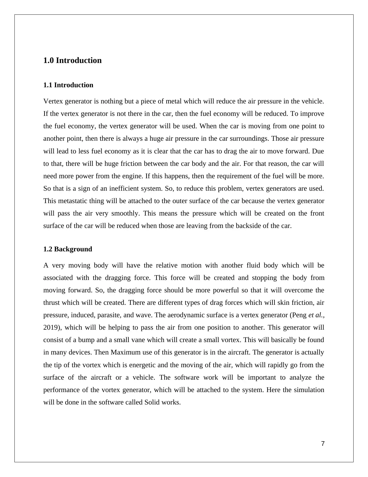
Vertex generator is nothing but a piece of metal which will reduce the air pressure in the vehicle.
If the vertex generator is not there in the car, then the fuel economy will be reduced. To improve
the fuel economy, the vertex generator will be used. When the car is moving from one point to
another point, then there is always a huge air pressure in the car surroundings. Those air pressure
will lead to less fuel economy as it is clear that the car has to drag the air to move forward. Due
to that, there will be huge friction between the car body and the air. For that reason, the car will
need more power from the engine. If this happens, then the requirement of the fuel will be more.
So that is a sign of an inefficient system. So, to reduce this problem, vertex generators are used.
This metastatic thing will be attached to the outer surface of the car because the vertex generator
will pass the air very smoothly. This means the pressure which will be created on the front
surface of the car will be reduced when those are leaving from the backside of the car.
1.2 Background
A very moving body will have the relative motion with another fluid body which will be
associated with the dragging force. This force will be created and stopping the body from
moving forward. So, the dragging force should be more powerful so that it will overcome the
thrust which will be created. There are different types of drag forces which will skin friction, air
pressure, induced, parasite, and wave. The aerodynamic surface is a vertex generator (Peng et al.,
2019), which will be helping to pass the air from one position to another. This generator will
consist of a bump and a small vane which will create a small vortex. This will basically be found
in many devices. Then Maximum use of this generator is in the aircraft. The generator is actually
the tip of the vortex which is energetic and the moving of the air, which will rapidly go from the
surface of the aircraft or a vehicle. The software work will be important to analyze the
performance of the vortex generator, which will be attached to the system. Here the simulation
will be done in the software called Solid works.
7
1.1 Introduction
Vertex generator is nothing but a piece of metal which will reduce the air pressure in the vehicle.
If the vertex generator is not there in the car, then the fuel economy will be reduced. To improve
the fuel economy, the vertex generator will be used. When the car is moving from one point to
another point, then there is always a huge air pressure in the car surroundings. Those air pressure
will lead to less fuel economy as it is clear that the car has to drag the air to move forward. Due
to that, there will be huge friction between the car body and the air. For that reason, the car will
need more power from the engine. If this happens, then the requirement of the fuel will be more.
So that is a sign of an inefficient system. So, to reduce this problem, vertex generators are used.
This metastatic thing will be attached to the outer surface of the car because the vertex generator
will pass the air very smoothly. This means the pressure which will be created on the front
surface of the car will be reduced when those are leaving from the backside of the car.
1.2 Background
A very moving body will have the relative motion with another fluid body which will be
associated with the dragging force. This force will be created and stopping the body from
moving forward. So, the dragging force should be more powerful so that it will overcome the
thrust which will be created. There are different types of drag forces which will skin friction, air
pressure, induced, parasite, and wave. The aerodynamic surface is a vertex generator (Peng et al.,
2019), which will be helping to pass the air from one position to another. This generator will
consist of a bump and a small vane which will create a small vortex. This will basically be found
in many devices. Then Maximum use of this generator is in the aircraft. The generator is actually
the tip of the vortex which is energetic and the moving of the air, which will rapidly go from the
surface of the aircraft or a vehicle. The software work will be important to analyze the
performance of the vortex generator, which will be attached to the system. Here the simulation
will be done in the software called Solid works.
7
Paraphrase This Document
Need a fresh take? Get an instant paraphrase of this document with our AI Paraphraser
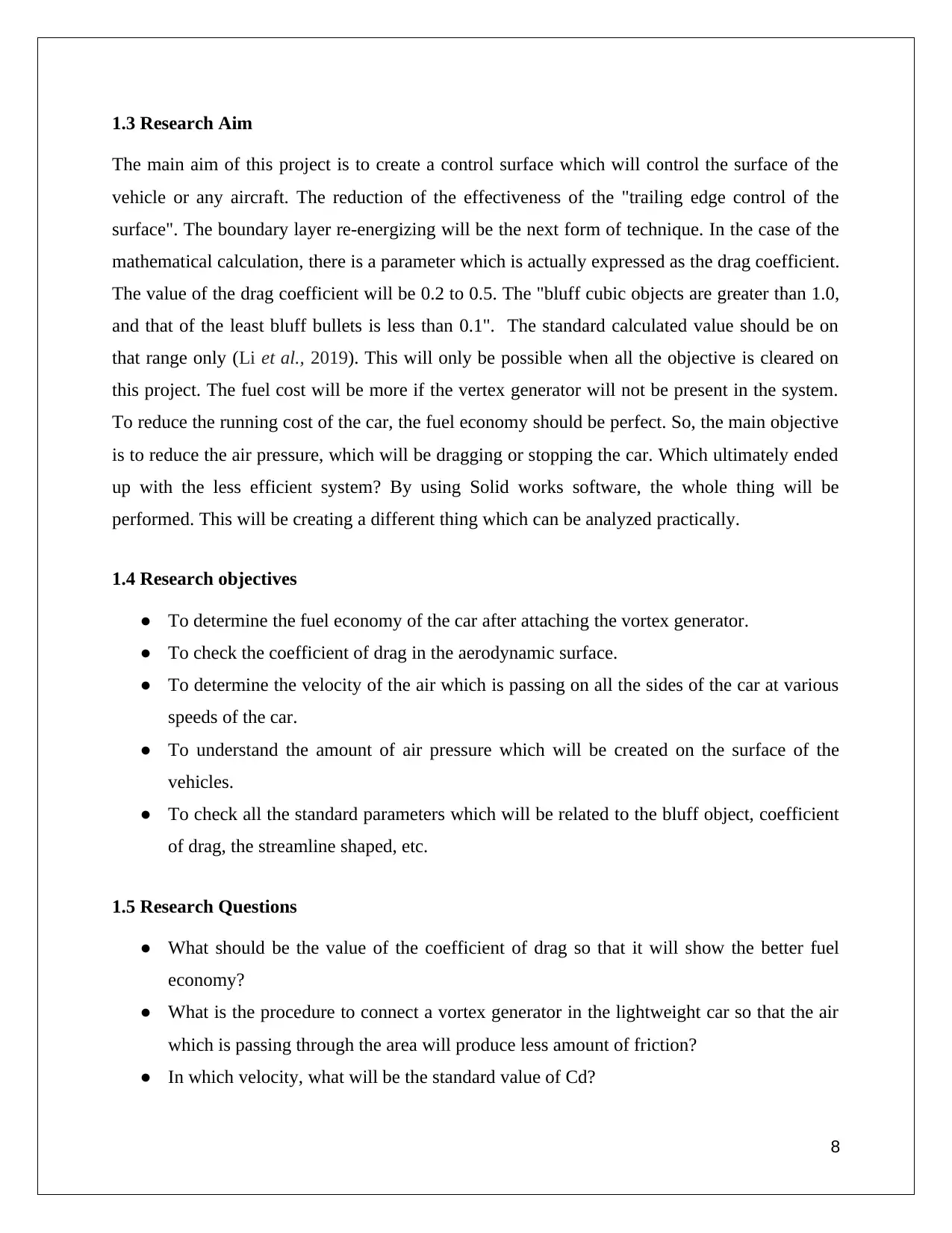
1.3 Research Aim
The main aim of this project is to create a control surface which will control the surface of the
vehicle or any aircraft. The reduction of the effectiveness of the "trailing edge control of the
surface". The boundary layer re-energizing will be the next form of technique. In the case of the
mathematical calculation, there is a parameter which is actually expressed as the drag coefficient.
The value of the drag coefficient will be 0.2 to 0.5. The "bluff cubic objects are greater than 1.0,
and that of the least bluff bullets is less than 0.1". The standard calculated value should be on
that range only (Li et al., 2019). This will only be possible when all the objective is cleared on
this project. The fuel cost will be more if the vertex generator will not be present in the system.
To reduce the running cost of the car, the fuel economy should be perfect. So, the main objective
is to reduce the air pressure, which will be dragging or stopping the car. Which ultimately ended
up with the less efficient system? By using Solid works software, the whole thing will be
performed. This will be creating a different thing which can be analyzed practically.
1.4 Research objectives
● To determine the fuel economy of the car after attaching the vortex generator.
● To check the coefficient of drag in the aerodynamic surface.
● To determine the velocity of the air which is passing on all the sides of the car at various
speeds of the car.
● To understand the amount of air pressure which will be created on the surface of the
vehicles.
● To check all the standard parameters which will be related to the bluff object, coefficient
of drag, the streamline shaped, etc.
1.5 Research Questions
● What should be the value of the coefficient of drag so that it will show the better fuel
economy?
● What is the procedure to connect a vortex generator in the lightweight car so that the air
which is passing through the area will produce less amount of friction?
● In which velocity, what will be the standard value of Cd?
8
● What is the relation between the drag force with the surface area, density of the air, and
the kinematic viscosity of the air?
1.6 Research Rationale
This research will be done for many reasons. In the various vehicle, there is the movement of
their physical body. Those bodies will actually have contact with the ground surface and the air
surface. Those two are reducing car efficiency (Yuan et al., 2019). The engine power will be
more wasted in these two aspects. The air source pressure will be more effective in all cases. In
the air, there is another factor which will come into the picture that is the air density. The density
of the air means the car will get more resistance. And if the car will get less resistance means the
air density will be less. This is the external factor which will be there. So, to reduce the external
fact, the proper vortex generator will be introduced. There will be lots of parameters which will
need to improve its Reynolds number, velocity, coefficient of drag. The force of the drag etc.
1.7 Research significance
The fuel cost will be more of the dynamic stability of the car will not be there properly. This will
only happen if the vertex generator is not present in the outer portion of the car. This fact will not
be effective if those components will not be present. The moment when those things are
attached, then the dynamic stability will be improved. When the air is passing through the
vehicle, then it will pass every portion of the body. So, the portion which actually feels more
pressure, on those portions, the vortex generator will be attached (Sundénet al., 2020). This will
help the car to move forward in an easy manner. This generator will be attached to each and
every portion of the car body. So, the main significance of the research is to provide dynamic
stability and also
provide more fuel economy. The research will be simulated in Solid works software. This
software shows the practical simulation of how the air will flow through the various parts of the
care body and where the air pressure will be maximum, which decreases the fuel economy.
9
⊘ This is a preview!⊘
Do you want full access?
Subscribe today to unlock all pages.
Trusted by 1+ million students worldwide
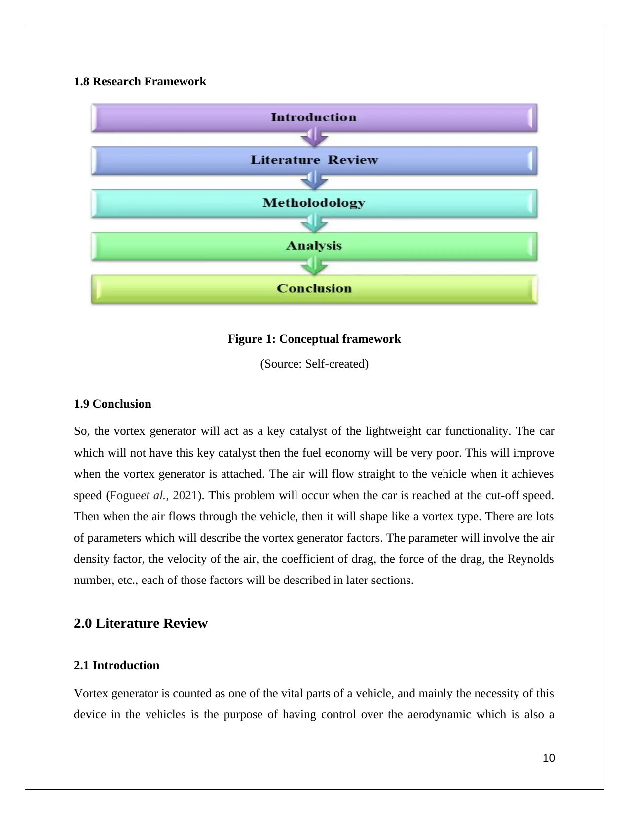
1.8 Research Framework
Figure 1: Conceptual framework
(Source: Self-created)
1.9 Conclusion
So, the vortex generator will act as a key catalyst of the lightweight car functionality. The car
which will not have this key catalyst then the fuel economy will be very poor. This will improve
when the vortex generator is attached. The air will flow straight to the vehicle when it achieves
speed (Fogueet al., 2021). This problem will occur when the car is reached at the cut-off speed.
Then when the air flows through the vehicle, then it will shape like a vortex type. There are lots
of parameters which will describe the vortex generator factors. The parameter will involve the air
density factor, the velocity of the air, the coefficient of drag, the force of the drag, the Reynolds
number, etc., each of those factors will be described in later sections.
2.0 Literature Review
2.1 Introduction
Vortex generator is counted as one of the vital parts of a vehicle, and mainly the necessity of this
device in the vehicles is the purpose of having control over the aerodynamic which is also a
10
Paraphrase This Document
Need a fresh take? Get an instant paraphrase of this document with our AI Paraphraser
property of the vehicle as well. The position of the vortex is on the upper surface of the vehicle.
This metallic device is not being used in each and every vehicle, especially the vehicle, which
are the aircraft and some specific cars. For those types of vehicles, this metallic device has been
inserted into the mechanism of the device. First of all, how does the generator works is what
needs to be researched, which is considered to be the basic area before the detailed research on
the vortex generator? For the aircraft, what happens is the airfoil of the vehicle is in continuous
motion with the air, and at that time of staying and traveling with the motion, the vortex
generator is usually made a vortex. So what happens is the airfoil which reacts according to the
motion of the air, has some of the boundary layers in the surface area, and often those boundary
layers are considered to be very slow and also further is effects as well as the local separation of
the flow and as a result, the aircraft becomes very slow which is why the vortex generator has
been implemented in the vehicle, and at the time of motion which is varied to the airfoil, the
vortex generator is used to operate as well as create the vortex.
11
2.2 Empirical Study
Ajarostaghi, 2021, according to this author, the main of the vortex generator is to make the factor
delay in the time of the flow, which is continuous under the air separation of the aircraft. And the
air separation happens at the time of the traveling, which is done by the surface of the object. The
implementation of the vortex generator is situated on the outer side of the aircraft, or in a simple
word, the external area of the vehicle is considered to be a place of implemented vortex
generator. The author says that the size and the shape of the vortex generator refer to a rectangle,
and sometimes it is considered to be a triangle in nature and size. Basically, aerodynamics is
meant for the study of air travel, and the platform or the surface by which the traveling has been
accomplished s considered to be a solid surface, and all these studies are under the mechanism of
aerodynamics. So mainly according to the author, the entire report is based on the purpose of
making a model on vortex generator so that in the aircraft the motion of the air can stay
continuous with the air and also as well the surface of the aircraft vehicle needs to be under the
control which means the surface controlling is also a very vital part of the aim in this report. The
placement of the generator has been done in a way that the generator can make an angle with
respect to the airflow of th vehicle, and the purpose of making the angle is considered to be the
attack which can be controlled as well as so that the attacks can be acquired. At the time of
creating the angle, the vortex is used established energy, and the energy has been connected to
the surface of the external structure, and the layers of the surfaces are also related to the flow of
the energy from the vortex generator. Sometimes at the aircraft and sometimes at the golf ball,
the use of a vortex generator is very common. In the case of the golf ball as well as the aircraft,
when the solid material or an object is moving from some certain place to some other place, and
that too with the flow of the air and also the layers of the surfaces which is considered to be the
surface of the air and layer is from the air itself so basically the time of the traveling of the object
under a certain surface the object is reportedly moved along with the layers of the air. In terms
of speed, the boundary layers of the air are often considered to be very slow and vicious as well.
Also, more often, it has been seen that the boundary which is under the air has been considered
to be totally separate from the particular object and which is why it creates the wake, and as a
result of the wake, the vehicle faces a lot of errors and one of the most vital error is the object is
being dragged and as well as the reduction in the speed also has been noticed. But the
12
⊘ This is a preview!⊘
Do you want full access?
Subscribe today to unlock all pages.
Trusted by 1+ million students worldwide
1 out of 48
Related Documents


Your All-in-One AI-Powered Toolkit for Academic Success.
+13062052269
info@desklib.com
Available 24*7 on WhatsApp / Email
![[object Object]](/_next/static/media/star-bottom.7253800d.svg)
Unlock your academic potential
Copyright © 2020–2026 A2Z Services. All Rights Reserved. Developed and managed by ZUCOL.