Detailed Investigation of RC Circuit: Time Constant and Capacitance
VerifiedAdded on 2021/06/14
|12
|2136
|141
Report
AI Summary
This report presents an investigation of RC circuits, focusing on determining the time constant and capacitance of two capacitors (C1 and C2). The study involves measuring voltage decay over time, generating voltage vs. time graphs, and calculating the time constant from both graphical analysis and formula-based methods. The experiment uses two different capacitors, with the collected data used to calculate time constants and capacitance values, followed by an error analysis to compare experimental and theoretical values. The report includes detailed calculations, graphical representations of the data, and a discussion of potential error sources, such as device defects and environmental factors. The findings indicate that the calculated values were close to the theoretical values, with small percentage differences, demonstrating the experiment's success in determining the required parameters.
Investigation of RC Circuit 1
INVESTIGATION OF RC CIRCUIT
Name
Course
Professor
University
City/state
Date
INVESTIGATION OF RC CIRCUIT
Name
Course
Professor
University
City/state
Date
Paraphrase This Document
Need a fresh take? Get an instant paraphrase of this document with our AI Paraphraser
Investigation of RC Circuit 2
Investigation of RC Circuit
Introduction
Voltage drop across a capacitor (VC) and resistor (VR) is given as Vc=Q
C and Vc=IR
respectively, where Q = charge, C = capacitance, I = current and R = resistance). C is measured
in farads (F), I is measured in amperes and R is measured in ohms. A capacitor is an element of
an RC circuit that stores an electric field energy by separating negative and positive charges on
opposite plates/terminals (Xia & Chen, 2017). The behavior of capacitors is different when they
are being charged and discharged. A capacitor is said to be charging when it is connected to a
battery, capacitor and resistor. On the other hand, a capacitor is said to be discharging when it is
connected to a capacitor and resistor but disconnected from the battery (Galeriu, et al., 2015);
(Lima, 2015).
Ohm’s law is governed by the equation V(t) = I(t)R (where V = voltage, I = current and R =
resistance of the circuit). But I ( t )=± dq(t )
dt , hence dq(t)
dt =± V (t )
R
During charging, voltage of a capacitor is given as follows: V ( t ) =ε (1−e
−t
τ ) (where ε =
electromagnetic force (emf).
During discharging, voltage of a capacitor is given as follows: V c ( t ) =Vo (e
−t
τ )
Time constant, τ, is calculated as follows: τ = RC (where R = resistance of the resistor in ohms
and C = capacitance of the capacitor in farads) (TranslatorsCafe.com, 2017). This equation can
Investigation of RC Circuit 3
be rearranged as follows: C = τ
R . Time constant can be determined using different methods, such
as experimental, calculus, etc. (Dunford, 2010); (Pereira, 2016).
There are various techniques of analyzing RC circuits – some are simple while others are
advanced depending on the technology used (Galeriu, 2014); (Pearce, 2013). This experiment
involved measuring voltage across two different resistors and capacitors within a specific time,
and using the data collected to determine the RC circuit’s time constant and capacitance of a
capacitor.
Tables
The measured and calculated values from the experiment are provided in Table 1 and 2 below
Table 1: Voltage and time against decay for C1
Voltage (V)
± 0.01V
Ln (V)
0.01
Time (s)
0.01s
6.24 1.83 0.00
5.28 1.66 6.00
4.36 1.47 12.00
3.60 1.28 18.00
3.00 1.10 24.00
2.48 0.908 30.00
2.32 0.842 32.00
1.72 0.542 42.00
1.48 0.392 48.00
1.16 0.148 54.00
Table 2: Voltage and time along decay for C2
Voltage (V)
± 0.01V
Ln (V)
0.01
Time (s)
0.01s
6.20 1.820 0.00
5.56 1.720 2.00
4.88 1.590 4.00
⊘ This is a preview!⊘
Do you want full access?
Subscribe today to unlock all pages.
Trusted by 1+ million students worldwide
Investigation of RC Circuit 4
4.28 1.450 6.00
3.76 1.320 8.00
3.32 1.200 10.00
2.88 1.060 12.00
2.56 0.940 14.00
2.24 0.806 16.00
1.96 0.673 18.00
Graphs
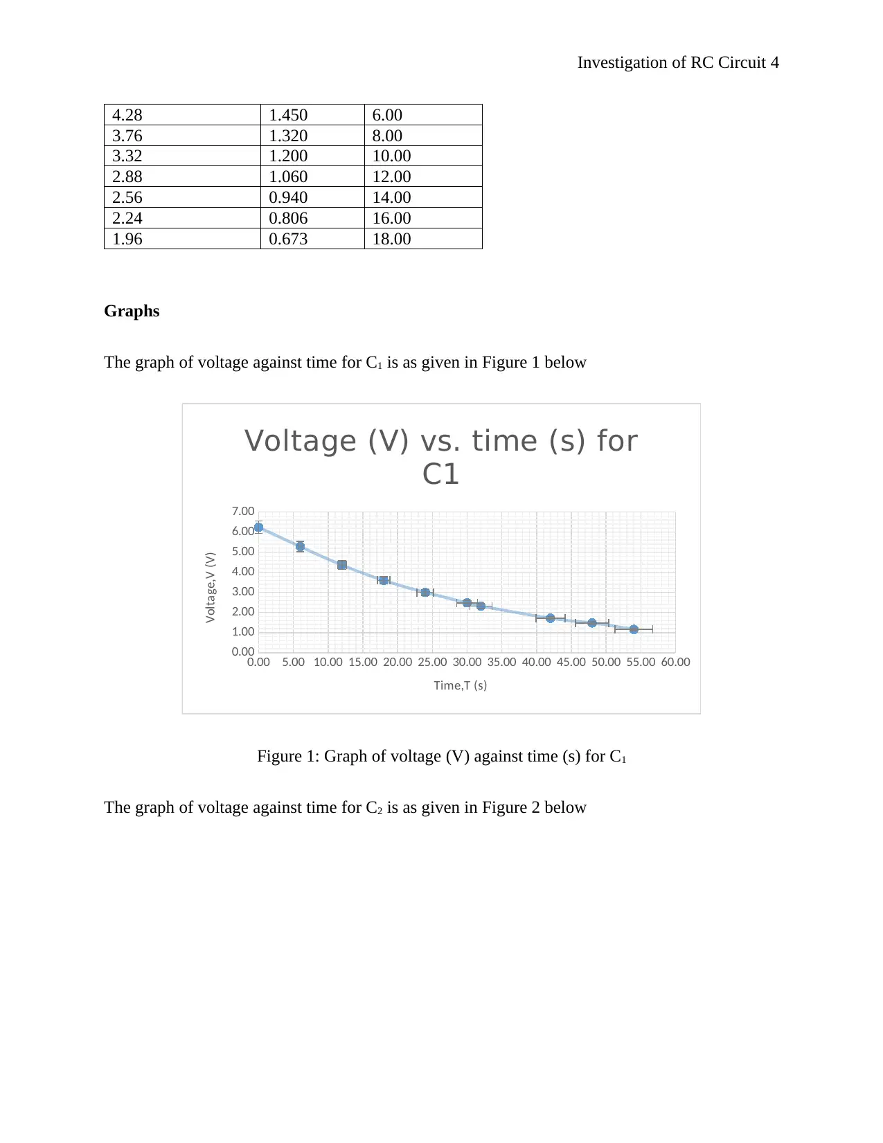
The graph of voltage against time for C1 is as given in Figure 1 below
0.00 5.00 10.00 15.00 20.00 25.00 30.00 35.00 40.00 45.00 50.00 55.00 60.00
0.00
1.00
2.00
3.00
4.00
5.00
6.00
7.00
Voltage (V) vs. time (s) for
C1
Time,T (s)
Voltage,V (V)
Figure 1: Graph of voltage (V) against time (s) for C1
The graph of voltage against time for C2 is as given in Figure 2 below
4.28 1.450 6.00
3.76 1.320 8.00
3.32 1.200 10.00
2.88 1.060 12.00
2.56 0.940 14.00
2.24 0.806 16.00
1.96 0.673 18.00
Graphs
The graph of voltage against time for C1 is as given in Figure 1 below
0.00 5.00 10.00 15.00 20.00 25.00 30.00 35.00 40.00 45.00 50.00 55.00 60.00
0.00
1.00
2.00
3.00
4.00
5.00
6.00
7.00
Voltage (V) vs. time (s) for
C1
Time,T (s)
Voltage,V (V)
Figure 1: Graph of voltage (V) against time (s) for C1
The graph of voltage against time for C2 is as given in Figure 2 below
Paraphrase This Document
Need a fresh take? Get an instant paraphrase of this document with our AI Paraphraser
Investigation of RC Circuit 5
0.00 2.00 4.00 6.00 8.00 10.00 12.00 14.00 16.00 18.00 20.00
0.00
1.00
2.00
3.00
4.00
5.00
6.00
7.00
Voltage (V) vs. time (s)
for C2
Time, T (s)
Voltage, V (V)
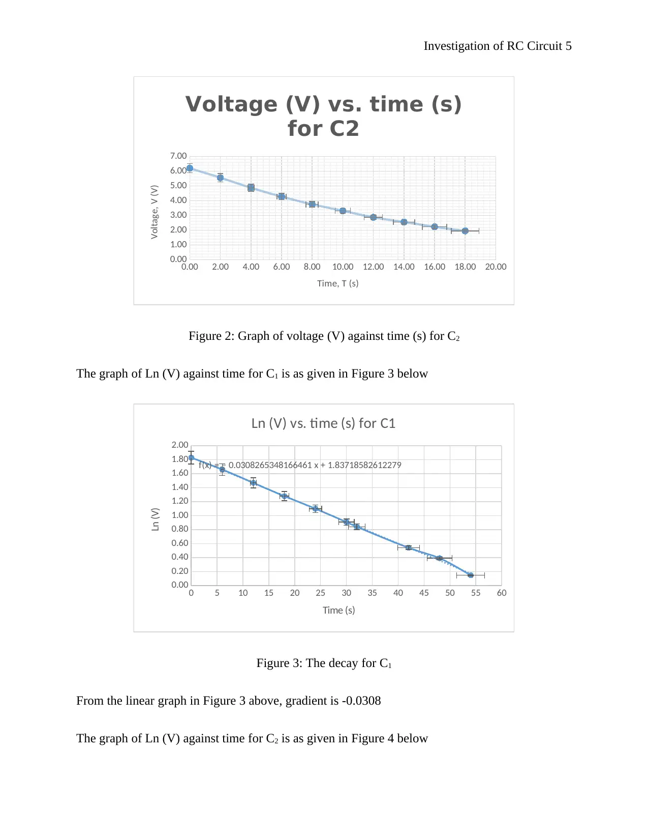
Figure 2: Graph of voltage (V) against time (s) for C2
The graph of Ln (V) against time for C1 is as given in Figure 3 below
0 5 10 15 20 25 30 35 40 45 50 55 60
0.00
0.20
0.40
0.60
0.80
1.00
1.20
1.40
1.60
1.80
2.00
f(x) = − 0.0308265348166461 x + 1.83718582612279
Ln (V) vs. time (s) for C1
Time (s)
Ln (V)
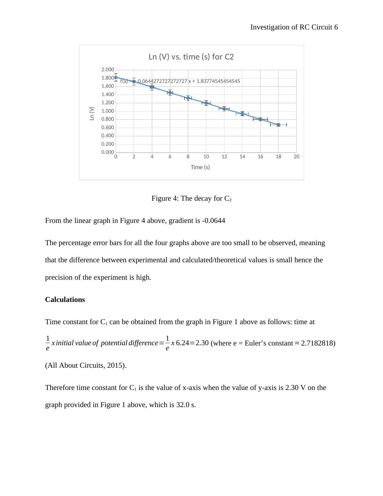
Figure 3: The decay for C1
From the linear graph in Figure 3 above, gradient is -0.0308
The graph of Ln (V) against time for C2 is as given in Figure 4 below
0.00 2.00 4.00 6.00 8.00 10.00 12.00 14.00 16.00 18.00 20.00
0.00
1.00
2.00
3.00
4.00
5.00
6.00
7.00
Voltage (V) vs. time (s)
for C2
Time, T (s)
Voltage, V (V)
Figure 2: Graph of voltage (V) against time (s) for C2
The graph of Ln (V) against time for C1 is as given in Figure 3 below
0 5 10 15 20 25 30 35 40 45 50 55 60
0.00
0.20
0.40
0.60
0.80
1.00
1.20
1.40
1.60
1.80
2.00
f(x) = − 0.0308265348166461 x + 1.83718582612279
Ln (V) vs. time (s) for C1
Time (s)
Ln (V)
Figure 3: The decay for C1
From the linear graph in Figure 3 above, gradient is -0.0308
The graph of Ln (V) against time for C2 is as given in Figure 4 below
Investigation of RC Circuit 6
0 2 4 6 8 10 12 14 16 18 20
0.000
0.200
0.400
0.600
0.800
1.000
1.200
1.400
1.600
1.800
2.000
f(x) = − 0.0644272727272727 x + 1.83774545454545
Ln (V) vs. time (s) for C2
Time (s)
Ln (V)
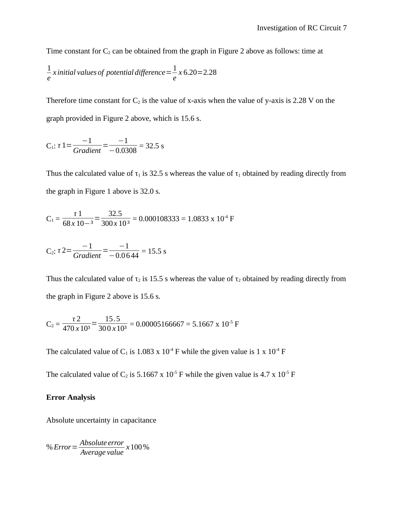
Figure 4: The decay for C2
From the linear graph in Figure 4 above, gradient is -0.0644
The percentage error bars for all the four graphs above are too small to be observed, meaning
that the difference between experimental and calculated/theoretical values is small hence the
precision of the experiment is high.
Calculations
Time constant for C1 can be obtained from the graph in Figure 1 above as follows: time at
1
e x initial value of potential difference= 1
e x 6.24=2.30 (where e = Euler’s constant ≈ 2.7182818)
(All About Circuits, 2015).
Therefore time constant for C1 is the value of x-axis when the value of y-axis is 2.30 V on the
graph provided in Figure 1 above, which is 32.0 s.
0 2 4 6 8 10 12 14 16 18 20
0.000
0.200
0.400
0.600
0.800
1.000
1.200
1.400
1.600
1.800
2.000
f(x) = − 0.0644272727272727 x + 1.83774545454545
Ln (V) vs. time (s) for C2
Time (s)
Ln (V)
Figure 4: The decay for C2
From the linear graph in Figure 4 above, gradient is -0.0644
The percentage error bars for all the four graphs above are too small to be observed, meaning
that the difference between experimental and calculated/theoretical values is small hence the
precision of the experiment is high.
Calculations
Time constant for C1 can be obtained from the graph in Figure 1 above as follows: time at
1
e x initial value of potential difference= 1
e x 6.24=2.30 (where e = Euler’s constant ≈ 2.7182818)
(All About Circuits, 2015).
Therefore time constant for C1 is the value of x-axis when the value of y-axis is 2.30 V on the
graph provided in Figure 1 above, which is 32.0 s.
⊘ This is a preview!⊘
Do you want full access?
Subscribe today to unlock all pages.
Trusted by 1+ million students worldwide
Investigation of RC Circuit 7
Time constant for C2 can be obtained from the graph in Figure 2 above as follows: time at
1
e x initial values of potential difference= 1
e x 6.20=2.28
Therefore time constant for C2 is the value of x-axis when the value of y-axis is 2.28 V on the
graph provided in Figure 2 above, which is 15.6 s.
C1: τ 1= −1
Gradient = −1
−0.0308 = 32.5 s
Thus the calculated value of τ1 is 32.5 s whereas the value of τ1 obtained by reading directly from
the graph in Figure 1 above is 32.0 s.
C1 = τ 1
68 x 10−³ = 32.5
300 x 10 ³ = 0.000108333 = 1.0833 x 10⁻⁴ F
C2: τ 2= −1
Gradient = −1
−0.0 6 44 = 15.5 s
Thus the calculated value of τ2 is 15.5 s whereas the value of τ2 obtained by reading directly from
the graph in Figure 2 above is 15.6 s.
C2 = τ 2
470 x 10³ = 15 .5
30 0 x 10³ = 0.00005166667 = 5.1667 x 10⁻⁵ F
The calculated value of C1 is 1.083 x 10⁻⁴ F while the given value is 1 x 10⁻⁴ F
The calculated value of C2 is 5.1667 x 10⁻⁵ F while the given value is 4.7 x 10⁻⁵ F
Error Analysis
Absolute uncertainty in capacitance
% Error= Absolute error
Average value x 100 %
Paraphrase This Document
Need a fresh take? Get an instant paraphrase of this document with our AI Paraphraser

Investigation of RC Circuit 8
Error% in voltage, V
C1: 0.01
2.30 x 100 %=0.43 %
C2: 0.01
2.28 x 100 %=0.44 %
Error% in gradient (Ln V)
C1: 0.01
0.842 x 100 %=1.19 %
C2: 0.01
0.806 x 100 %=1.24 %
Error% in time constant, τ
C1: 0.01
32.5 x 100 %=0.03 %
C2: 0.01
15.5 x 100 %=0.06 %
Total Error% in capacitance
C1: 0.43 + 1.19 + 0.03 = 1.65%
C2: 0.44 + 1.24 + 0.06 = 1.74%
Absolute error in capacitance
C1: 1.65
100 x 1.0833 x 10−4
= 0.018 x 10⁻⁴
C1 = ( 1.0833 ± 0.018 ) x 10−4 F
Investigation of RC Circuit 9
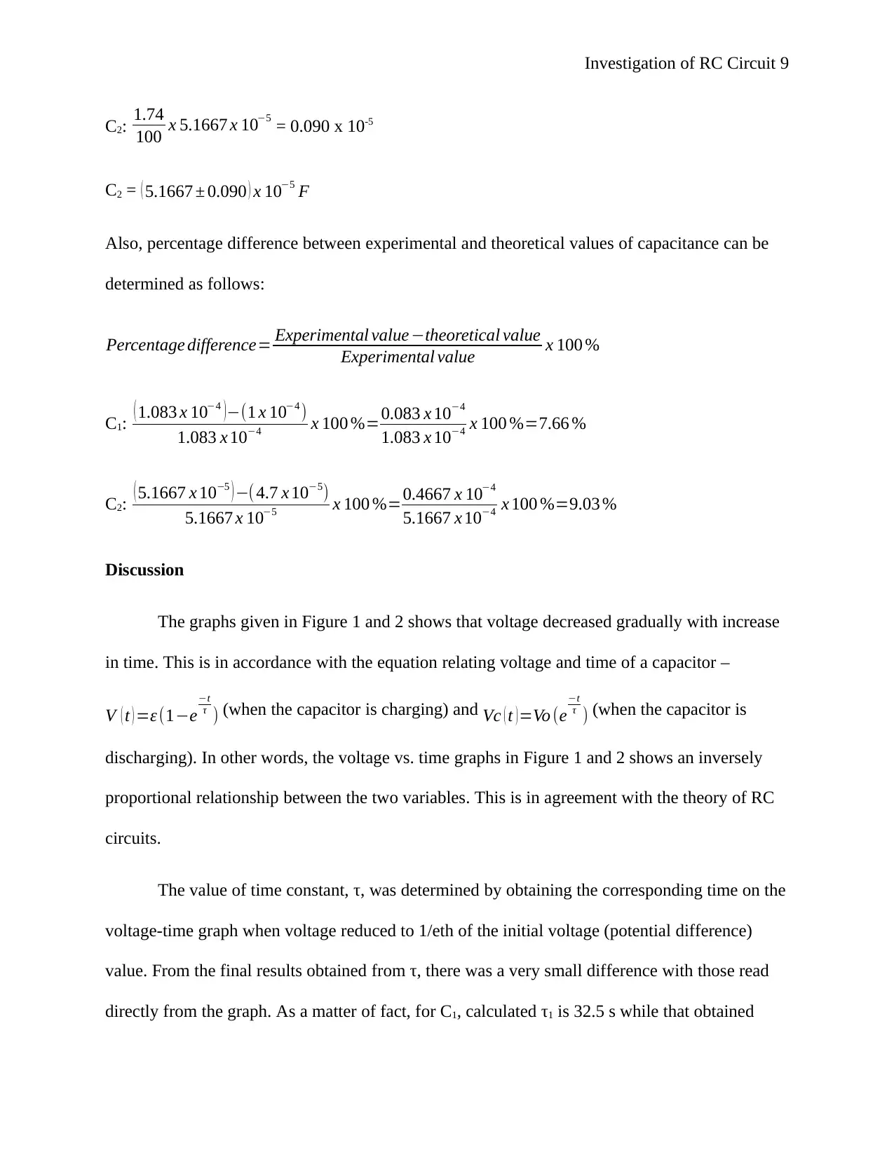
C2: 1.74
100 x 5.1667 x 10−5 = 0.090 x 10⁻⁵
C2 = ( 5.1667 ± 0.090 ) x 10−5 F
Also, percentage difference between experimental and theoretical values of capacitance can be
determined as follows:
Percentage difference= Experimental value−theoretical value
Experimental value x 100 %
C1: ( 1.083 x 10⁻⁴ )−(1 x 10⁻⁴ )
1.083 x 10−4 x 100 %=0.083 x 10⁻⁴
1.083 x 10−4 x 100 %=7.66 %
C2: ( 5.1667 x 10⁻⁵ ) −( 4.7 x 10⁻⁵)
5.1667 x 10−5 x 100 %=0.4667 x 10⁻⁴
5.1667 x 10−4 x 100 %=9.03 %
Discussion
The graphs given in Figure 1 and 2 shows that voltage decreased gradually with increase
in time. This is in accordance with the equation relating voltage and time of a capacitor –
V ( t ) =ε (1−e
−t
τ ) (when the capacitor is charging) and Vc ( t )=Vo (e
−t
τ ) (when the capacitor is
discharging). In other words, the voltage vs. time graphs in Figure 1 and 2 shows an inversely
proportional relationship between the two variables. This is in agreement with the theory of RC
circuits.
The value of time constant, τ, was determined by obtaining the corresponding time on the
voltage-time graph when voltage reduced to 1/eth of the initial voltage (potential difference)
value. From the final results obtained from τ, there was a very small difference with those read
directly from the graph. As a matter of fact, for C1, calculated τ1 is 32.5 s while that obtained
⊘ This is a preview!⊘
Do you want full access?
Subscribe today to unlock all pages.
Trusted by 1+ million students worldwide
Investigation of RC Circuit 10
from the graph is 32.0 s (a percentage difference of 1.54%). For C2, calculated τ2 is 15.5 s while
that obtained from the graph is 15.6 s (a percentage difference of 0.64%). Thus the difference is
insignificant based on the low percentage difference. If the RC circuit does not have initial
charge, its time constant is taken as the time taken for the capacitor to attain 63.2% of its
maximum charge capacity. At this time, the capacitor will be almost fully charged (usually
99.3% full) (TranslatorsCafe.com, 2017). The capacitor gets fully charged at five times its time
constant (5T) (Electronics Tutorials, 2017).
The value of capacitance obtained from this experiment was ( 1.0833 ± 0.018 ) x 10−4 F for
C1. This value is slightly different from the given value of 1 x 10-4 F by 0.0833 F. On the other
hand, the value of capacitance obtained from this experiment was ( 5.1667 ± 0.090 ) x 10−5 F for C2.
This value is also slightly different from the given value of 4.7 x 10-5 F by 0.4667 F. This means
that the limits of the absolute error are not precisely sufficient to account for the change between
experimental and reference/theoretical values.
The percentage difference between calculate and reference values of capacitance for C1
was 7.66% while the percentage difference between calculated and reference values of
capacitance for C2 was 9.03%. This difference is due to various errors when performing the
experiment. The errors included both systematic and random errors. Some of the possible
sources of errors during the experiment include use of defective measuring devices that made it
difficult to read measurements correctly or gave inaccurate readings thus resulting to systematic
errors when measuring voltage and time. Use of old or unclear devices may also have made it
difficult to read measurements easily and accurately thus compromising the precision of
readings. The errors may also have resulted from factors such as varying temperature and
pressure in the experiment room, which affected the precision of measuring instruments
Paraphrase This Document
Need a fresh take? Get an instant paraphrase of this document with our AI Paraphraser
Investigation of RC Circuit 11
especially the voltmeter. Last but not least, incorrect reading and recording of measurements, and
use of incorrect formulas may have contributed to final errors.
The experiment can be improved in the future by ensuring that all devices used are
checked prior to the experiment to confirm that they are not defective in any way. Environmental
conditions inside the experiment room should also be maintained constant during the experiment
by preventing substantial entry or exit of heat and/or into and from the room. Last but not least,
appropriate procedures should be followed to take measurements and the correct formulas used
to make calculation throughout the experiment.
Conclusion
The main aim of this experiment was to determine time constant and capacitance for C1
and C2 – this has been achieved. The time constant for C1, τ1, was found to be 32.5 s while time
constant for C2, τ2, was found to be 15.5 s. The capacitance for C1 with absolute error was found
to be ( 1.0833 ± 0.018 ) x 10−4 F while the capacitance for C2 with absolute error was found to be
( 5.1667 ± 0.090 ) x 10−5 F. Comparing these values with reference values, the percentage
difference between calculated and reference value for C1 was 7.66% while that for C2 was
9.03%. These percentage differences are very small and therefore insignificant. However, they
can be reduced further by implementing the improvement measures discussed in the section
above. Generally, this experiment was a success because the required parameters – time constant
and capacitance, were determined. The experiment was also a success because the percentage
error between the final calculated values of capacitance and the reference values was relatively
small.
Investigation of RC Circuit 12
References
All About Circuits, 2015. Voltage and Current Calculations. [Online]
Available at: https://www.allaboutcircuits.com/textbook/direct-current/chpt-16/voltage-current-
calculations/
[Accessed 27 June 2018].
Dunford, S., 2010. Calculating the Time Constant of an RC Circuit. Undergraduate Journal of
Mathematical Modeling: One + Two, 2(2).
Electronics Tutorials, 2017. RC Charging Circuit. [Online]
Available at: https://www.electronics-tutorials.ws/rc/rc_1.html
[Accessed 27 June 2018].
Galeriu, C., 2014. An Arduino Investigation of Simple Harmonic Motion. The Physics Teacher, 52(3).
Galeriu, C., Letson, C. & Esper, G., 2015. An Arduino Investigation of the RC Circuit. The Physics Teacher,
53(5).
Lima, F., 2015. A Better Criterion for the Discharging Time in an RC Circuit. The Physics Teacher, 53(1).
Pearce, J., 2013. Commentary: Open-source hardware for research and education. Physics Today,
66(11), pp. 1-8.
Pereira, N., 2016. Measuring the RC time constant with Arduino. Physics Education, 51(6).
TranslatorsCafe.com, 2017. Resistor-Capacitor (RC) Circuit Calculator. [Online]
Available at: https://www.translatorscafe.com/unit-converter/NO/calculator/rc-circuit/
[Accessed 27 June 2018].
Xia, S. & Chen, L., 2017. Theoretical and experimental investigation of optimal capacitor charging
process in RC circuit. The European Physical Journal Plus, 132(235).
⊘ This is a preview!⊘
Do you want full access?
Subscribe today to unlock all pages.
Trusted by 1+ million students worldwide
1 out of 12


Your All-in-One AI-Powered Toolkit for Academic Success.
+13062052269
info@desklib.com
Available 24*7 on WhatsApp / Email
![[object Object]](/_next/static/media/star-bottom.7253800d.svg)
Unlock your academic potential
Copyright © 2020–2026 A2Z Services. All Rights Reserved. Developed and managed by ZUCOL.