IoT Network Design for Sydney Smart Office and Remote Control from Bathurst Office
Verified
Added on  2023/06/08
|12
|847
|53
AI Summary
This article discusses the design of an IoT network for a smart office in Sydney and remote control of IoT devices from Bathurst office. It includes packet tracer files and bibliography.
Contribute Materials
Your contribution can guide someone’s learning journey. Share your
documents today.
Running head: IOT NETWORK DESIGN IoT Network Design Name of the Student Name of the University Author’s Note
Secure Best Marks with AI Grader
Need help grading? Try our AI Grader for instant feedback on your assignments.
1 IOT NETWORK DESIGN Table of Contents Sydney Smart Office Design:.....................................................................................................2 Controlling Sydney Office Smart IoT Device from Bathurst Office.........................................7 Packet tracer file.......................................................................................................................10 Bibliography.............................................................................................................................11
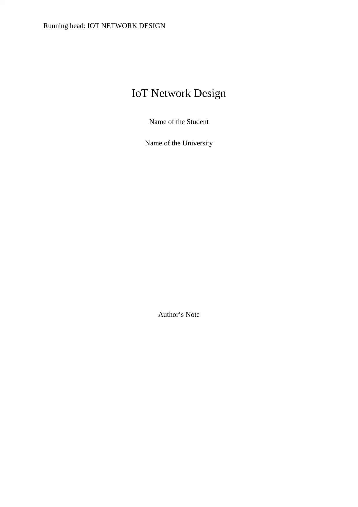
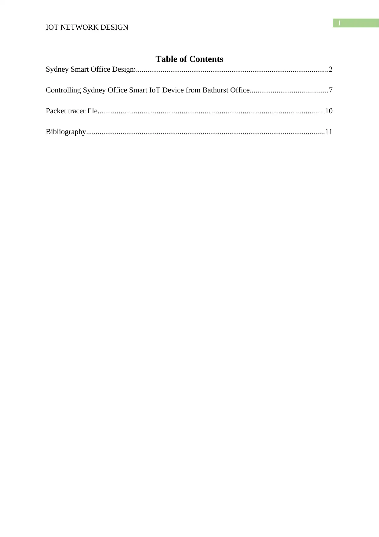
2 IOT NETWORK DESIGN Sydney Smart Office Design: Figure 1: Adding the IoT device in the network Figure 2: Choosing the network adapter for wireless connectivity
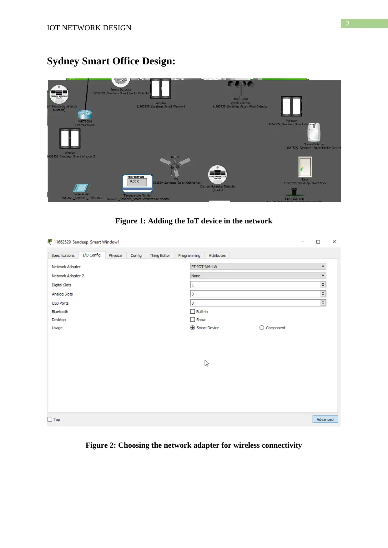
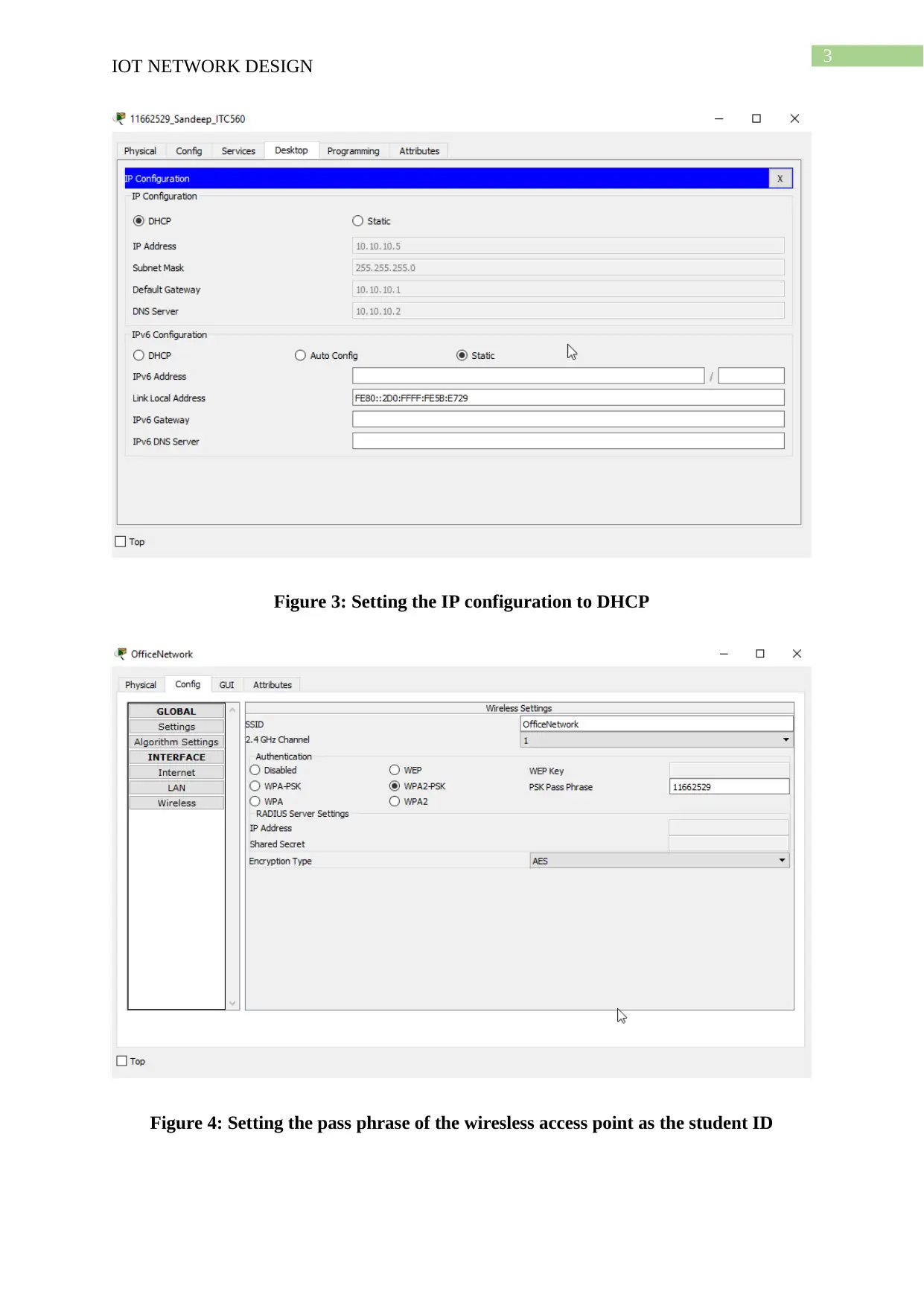
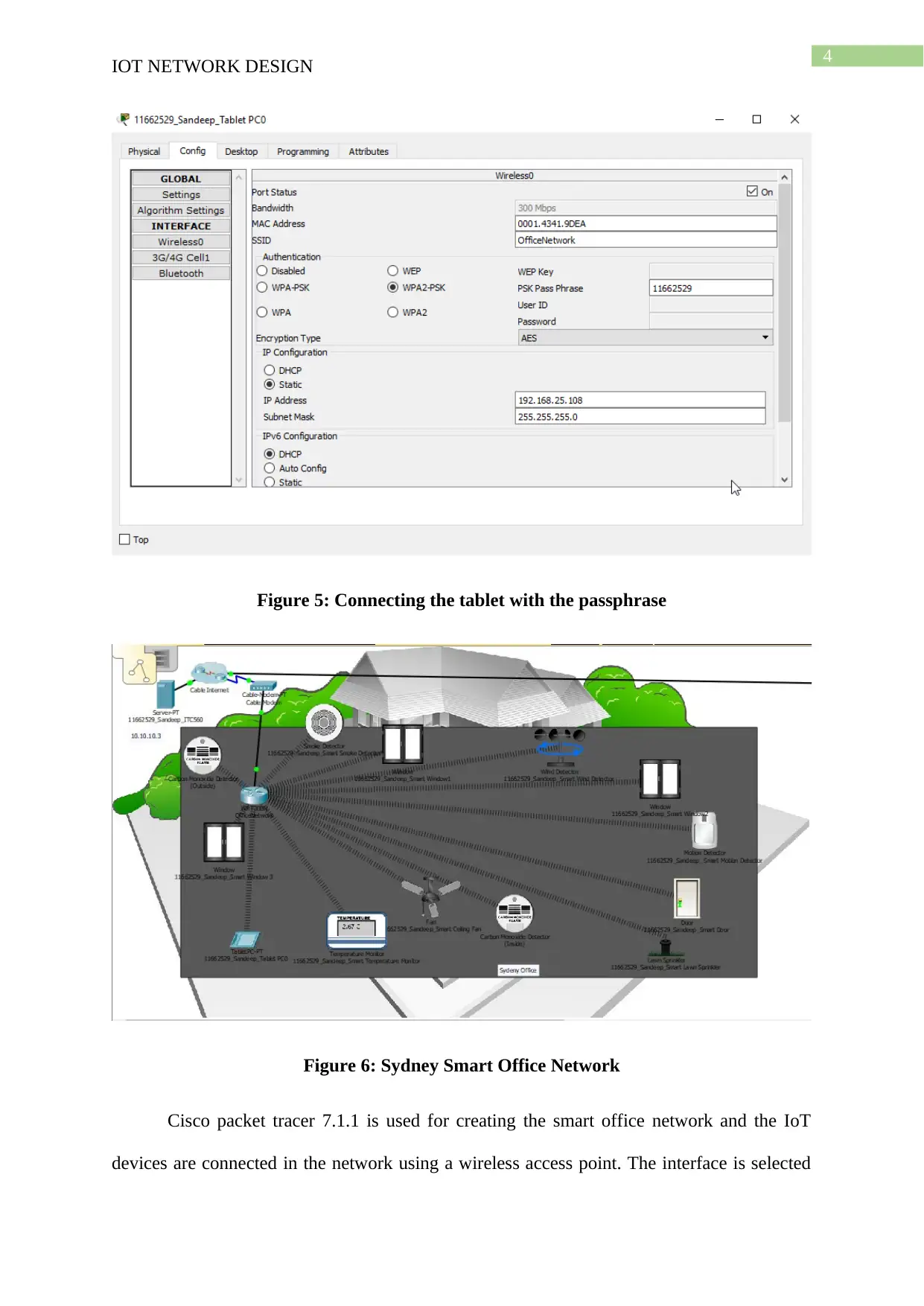
3 IOT NETWORK DESIGN Figure 3: Setting the IP configuration to DHCP Figure 4: Setting the pass phrase of the wiresless access point as the student ID
Paraphrase This Document
Need a fresh take? Get an instant paraphrase of this document with our AI Paraphraser
4 IOT NETWORK DESIGN Figure 5: Connecting the tablet with the passphrase Figure 6: Sydney Smart Office Network Cisco packet tracer 7.1.1 is used for creating the smart office network and the IoT devices are connected in the network using a wireless access point. The interface is selected
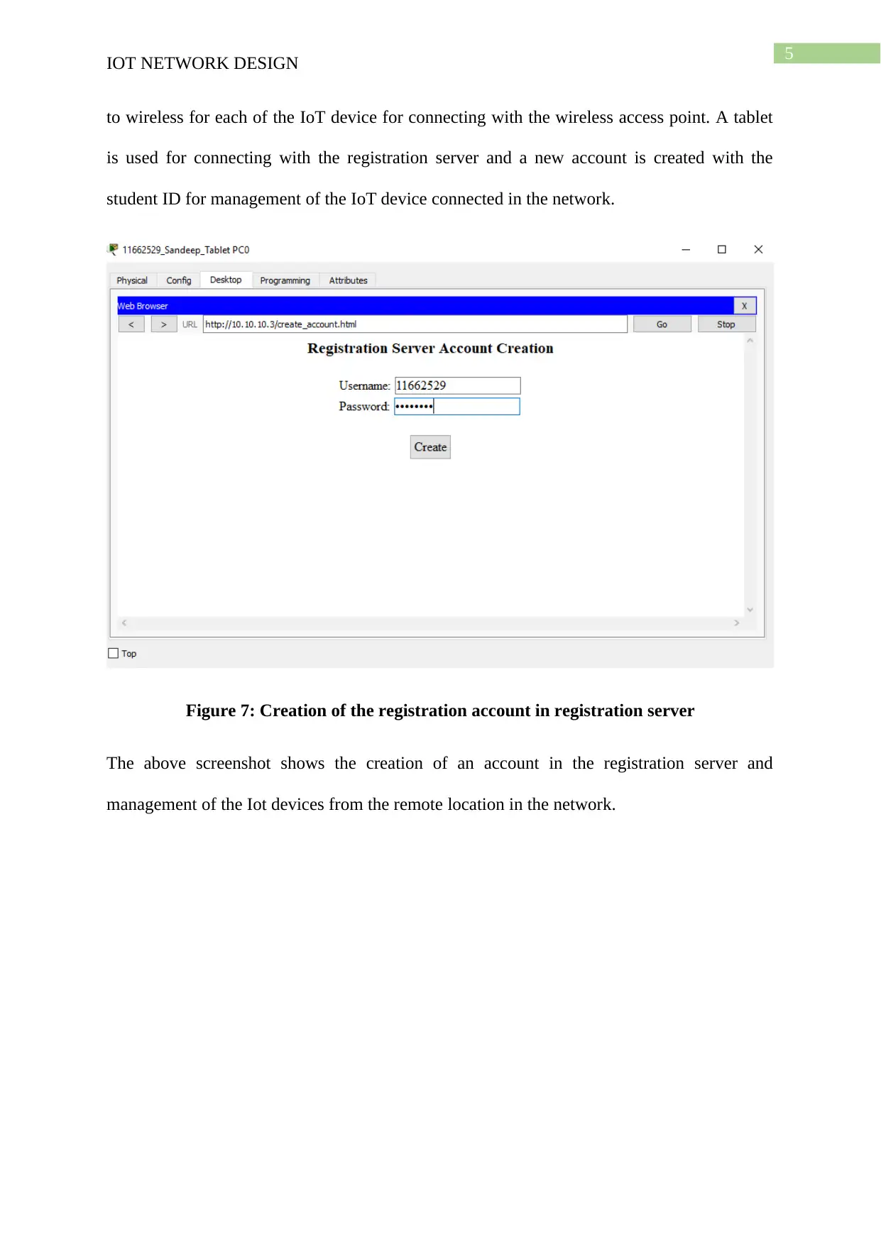
5 IOT NETWORK DESIGN to wireless for each of the IoT device for connecting with the wireless access point. A tablet is used for connecting with the registration server and a new account is created with the student ID for management of the IoT device connected in the network. Figure 7: Creation of the registration account in registration server The above screenshot shows the creation of an account in the registration server and management of the Iot devices from the remote location in the network.
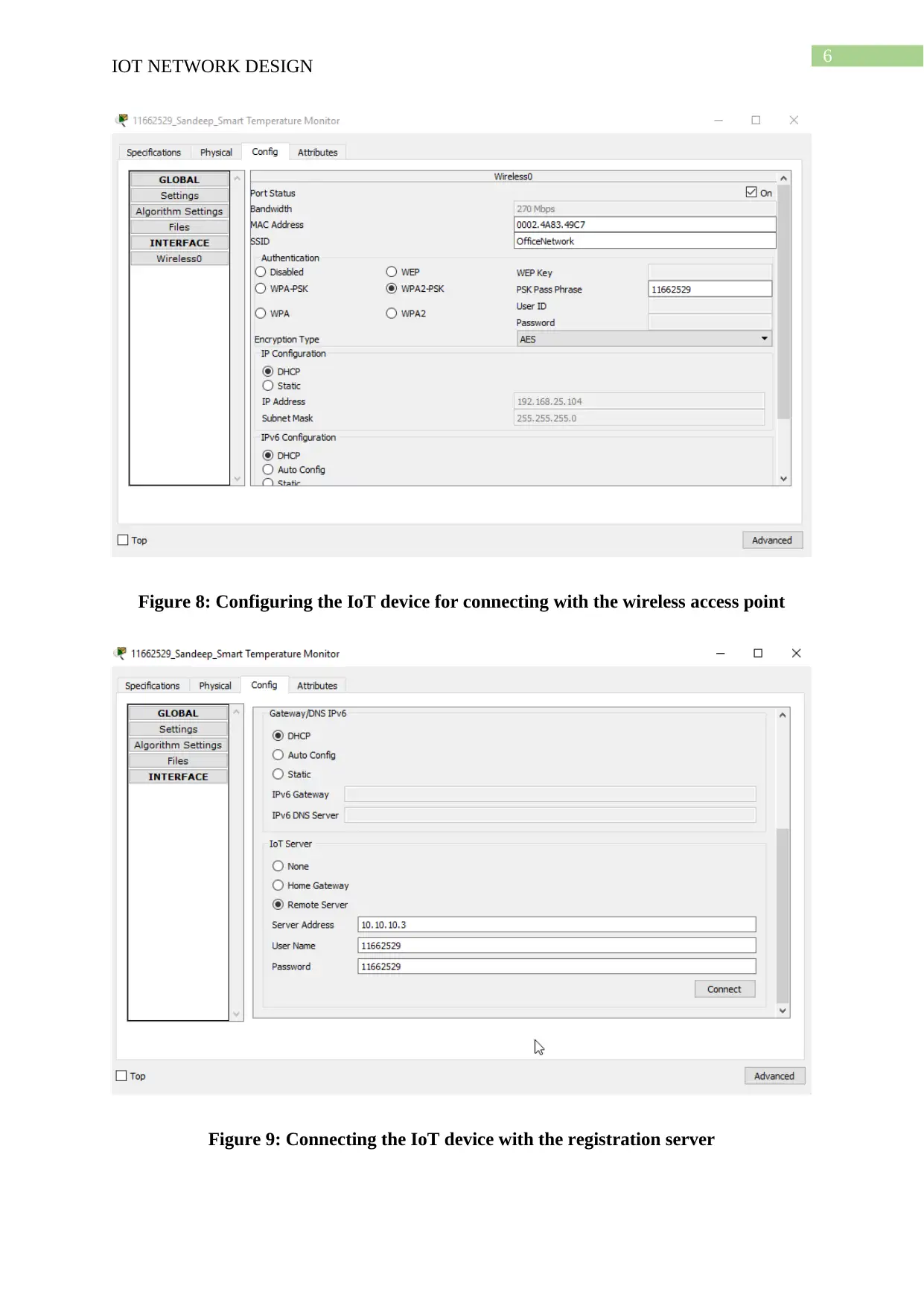
6 IOT NETWORK DESIGN Figure 8: Configuring the IoT device for connecting with the wireless access point Figure 9: Connecting the IoT device with the registration server
Secure Best Marks with AI Grader
Need help grading? Try our AI Grader for instant feedback on your assignments.
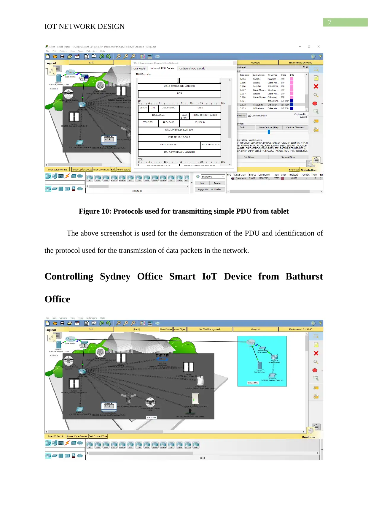
7 IOT NETWORK DESIGN Figure 10: Protocols used for transmitting simple PDU from tablet The above screenshot is used for the demonstration of the PDU and identification of the protocol used for the transmission of data packets in the network. ControllingSydneyOfficeSmartIoTDevicefromBathurst Office
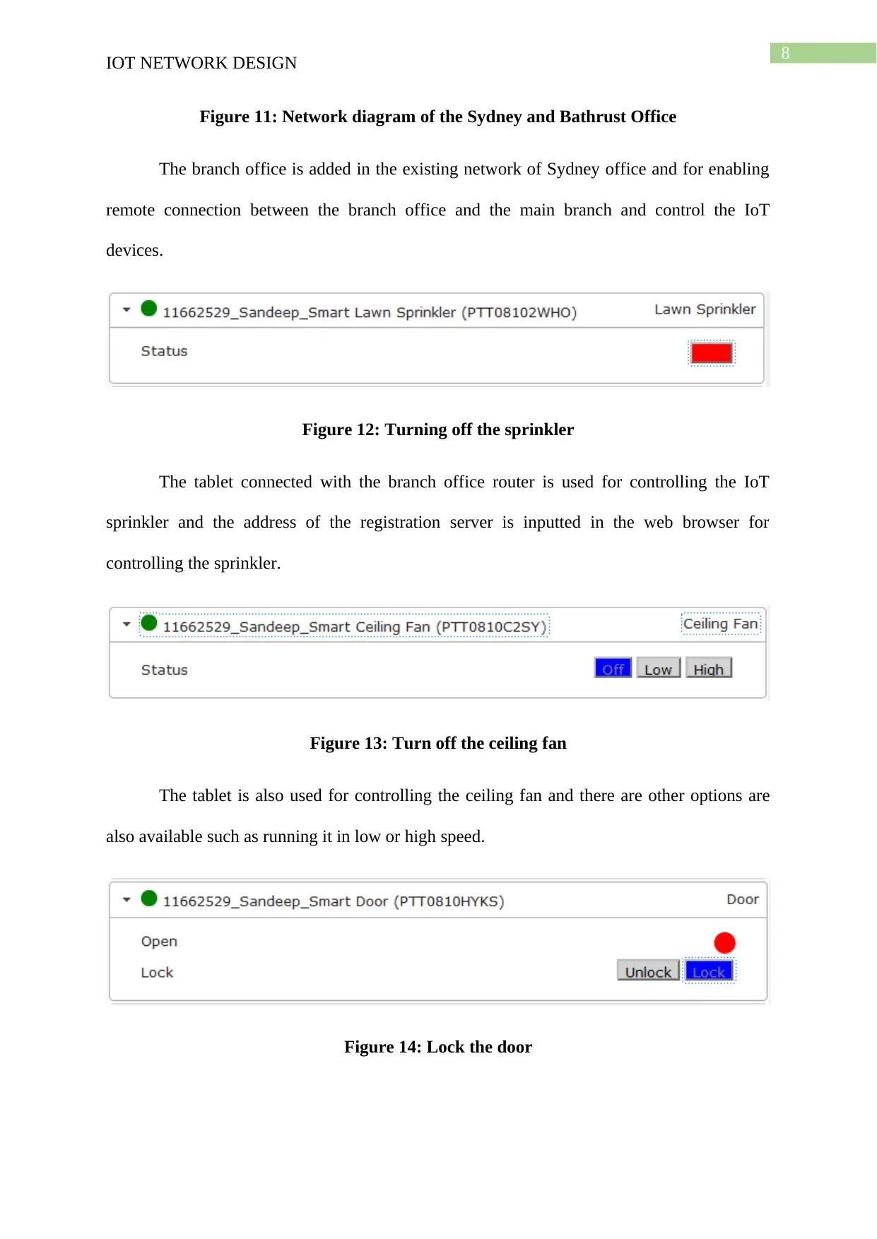
8 IOT NETWORK DESIGN Figure 11: Network diagram of the Sydney and Bathrust Office The branch office is added in the existing network of Sydney office and for enabling remote connection between the branch office and the main branch and control the IoT devices. Figure 12: Turning off the sprinkler The tablet connected with the branch office router is used for controlling the IoT sprinkler and the address of the registration server is inputted in the web browser for controlling the sprinkler. Figure 13: Turn off the ceiling fan The tablet is also used for controlling the ceiling fan and there are other options are also available such as running it in low or high speed. Figure 14: Lock the door
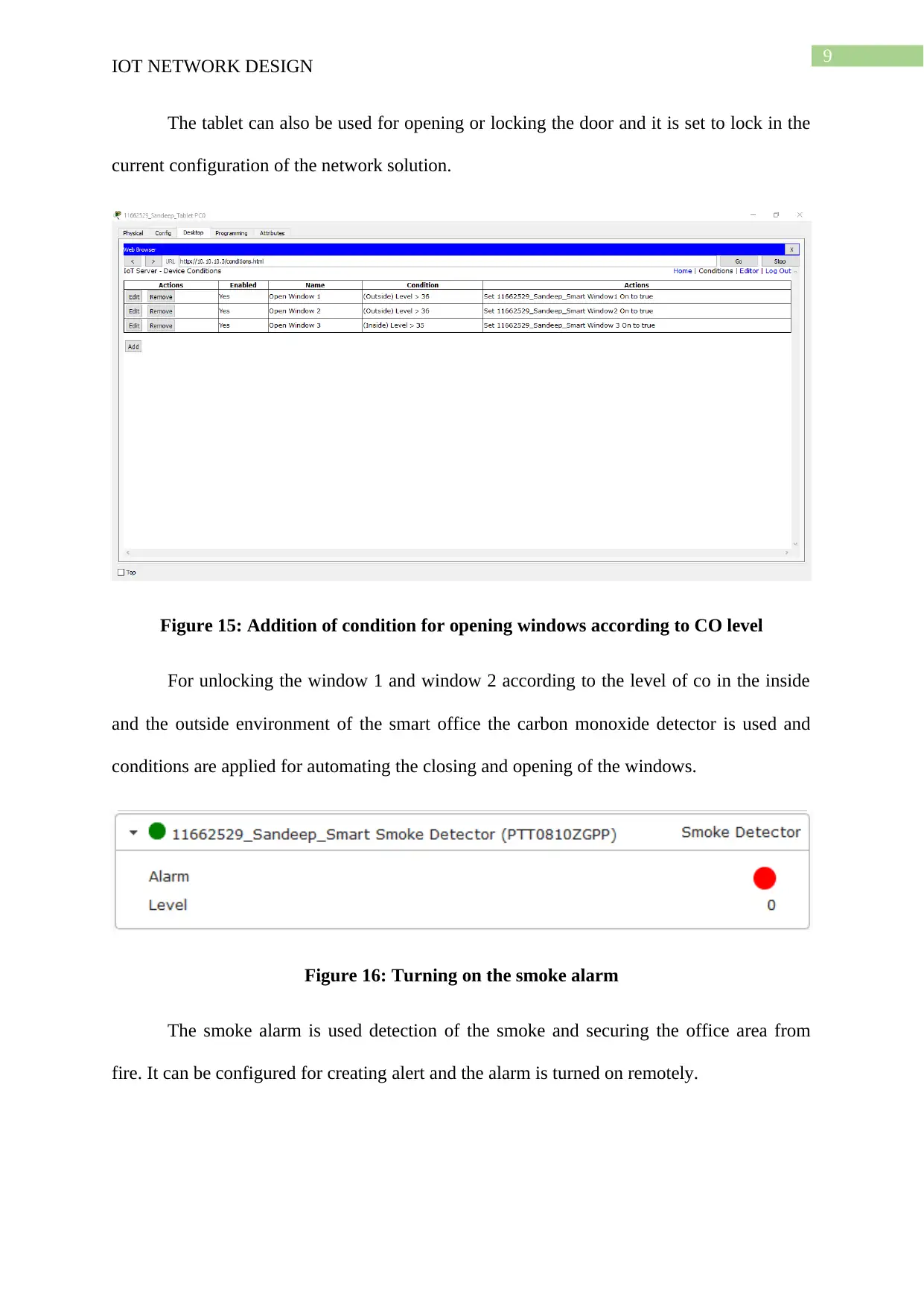
9 IOT NETWORK DESIGN The tablet can also be used for opening or locking the door and it is set to lock in the current configuration of the network solution. Figure 15: Addition of condition for opening windows according to CO level For unlocking the window 1 and window 2 according to the level of co in the inside and the outside environment of the smart office the carbon monoxide detector is used and conditions are applied for automating the closing and opening of the windows. Figure 16: Turning on the smoke alarm The smoke alarm is used detection of the smoke and securing the office area from fire. It can be configured for creating alert and the alarm is turned on remotely.
Paraphrase This Document
Need a fresh take? Get an instant paraphrase of this document with our AI Paraphraser
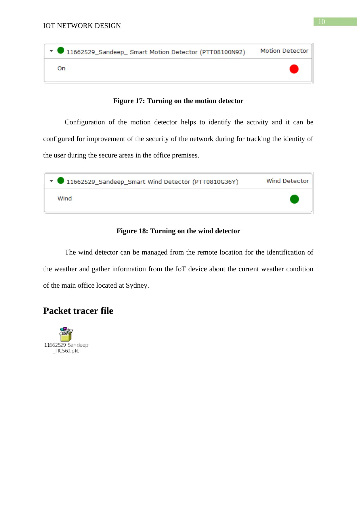
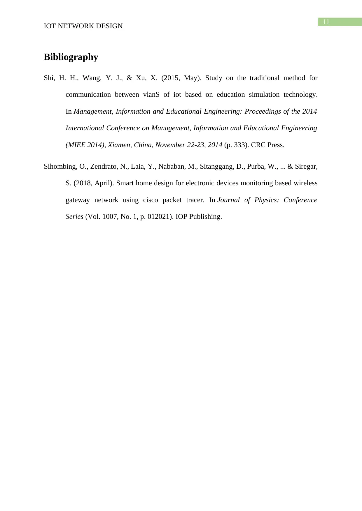
10 IOT NETWORK DESIGN Figure 17: Turning on the motion detector Configuration of the motion detector helps to identify the activity and it can be configured for improvement of the security of the network during for tracking the identity of the user during the secure areas in the office premises. Figure 18: Turning on the wind detector The wind detector can be managed from the remote location for the identification of the weather and gather information from the IoT device about the current weather condition of the main office located at Sydney. Packet tracer file
11 IOT NETWORK DESIGN Bibliography Shi, H. H., Wang, Y. J., & Xu, X. (2015, May). Study on the traditional method for communication between vlanS of iot based on education simulation technology. InManagement, Information and Educational Engineering: Proceedings of the 2014 International Conference on Management, Information and Educational Engineering (MIEE 2014), Xiamen, China, November 22-23, 2014(p. 333). CRC Press. Sihombing, O., Zendrato, N., Laia, Y., Nababan, M., Sitanggang, D., Purba, W., ... & Siregar, S. (2018, April). Smart home design for electronic devices monitoring based wireless gatewaynetworkusingciscopackettracer.InJournalofPhysics:Conference Series(Vol. 1007, No. 1, p. 012021). IOP Publishing.