ITEC250, Fall 2018 Assignment
VerifiedAdded on 2023/06/04
|8
|1701
|187
AI Summary
This assignment covers topics such as subnet calculation, network expansion, DNS server deployment, web server management, web server traffic distribution, DNS implementation, DNS updates manipulation, and Time To Live (TTL) configuration in DNS.
Contribute Materials
Your contribution can guide someone’s learning journey. Share your
documents today.

Running head: ITEC250 FALL 2018 ASSIGNMENT 1
ITEC250, Fall 2018 Assignment
Name
Institution
Date
ITEC250, Fall 2018 Assignment
Name
Institution
Date
Secure Best Marks with AI Grader
Need help grading? Try our AI Grader for instant feedback on your assignments.
ITEC250, FALL 2018 ASSIGNMENT 2
Scenario 1-1: Calculation of Subnets
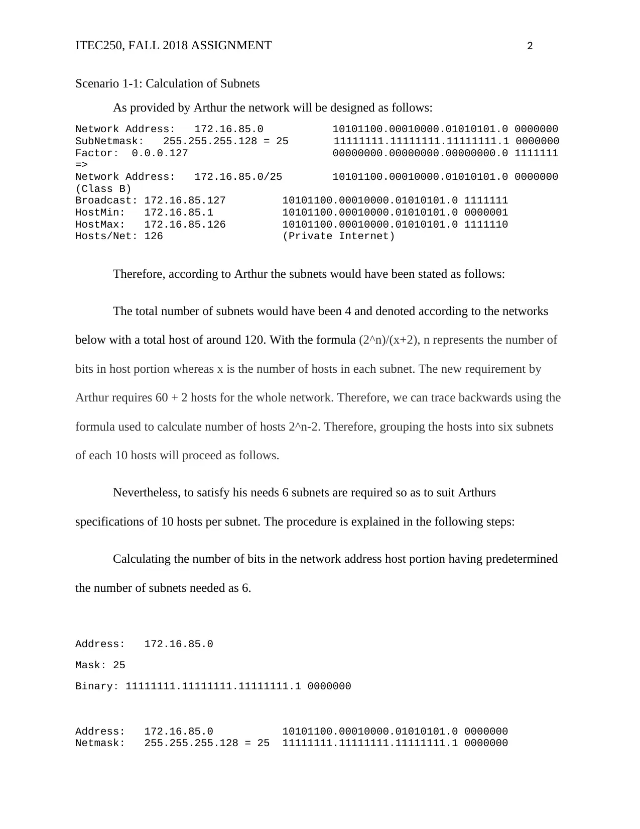
As provided by Arthur the network will be designed as follows:
Network Address: 172.16.85.0 10101100.00010000.01010101.0 0000000
SubNetmask: 255.255.255.128 = 25 11111111.11111111.11111111.1 0000000
Factor: 0.0.0.127 00000000.00000000.00000000.0 1111111
=>
Network Address: 172.16.85.0/25 10101100.00010000.01010101.0 0000000
(Class B)
Broadcast: 172.16.85.127 10101100.00010000.01010101.0 1111111
HostMin: 172.16.85.1 10101100.00010000.01010101.0 0000001
HostMax: 172.16.85.126 10101100.00010000.01010101.0 1111110
Hosts/Net: 126 (Private Internet)
Therefore, according to Arthur the subnets would have been stated as follows:
The total number of subnets would have been 4 and denoted according to the networks
below with a total host of around 120. With the formula (2^n)/(x+2), n represents the number of
bits in host portion whereas x is the number of hosts in each subnet. The new requirement by
Arthur requires 60 + 2 hosts for the whole network. Therefore, we can trace backwards using the
formula used to calculate number of hosts 2^n-2. Therefore, grouping the hosts into six subnets
of each 10 hosts will proceed as follows.
Nevertheless, to satisfy his needs 6 subnets are required so as to suit Arthurs
specifications of 10 hosts per subnet. The procedure is explained in the following steps:
Calculating the number of bits in the network address host portion having predetermined
the number of subnets needed as 6.
Address: 172.16.85.0
Mask: 25
Binary: 11111111.11111111.11111111.1 0000000
Address: 172.16.85.0 10101100.00010000.01010101.0 0000000
Netmask: 255.255.255.128 = 25 11111111.11111111.11111111.1 0000000
ITEC250, FALL 2018 ASSIGNMENT 3
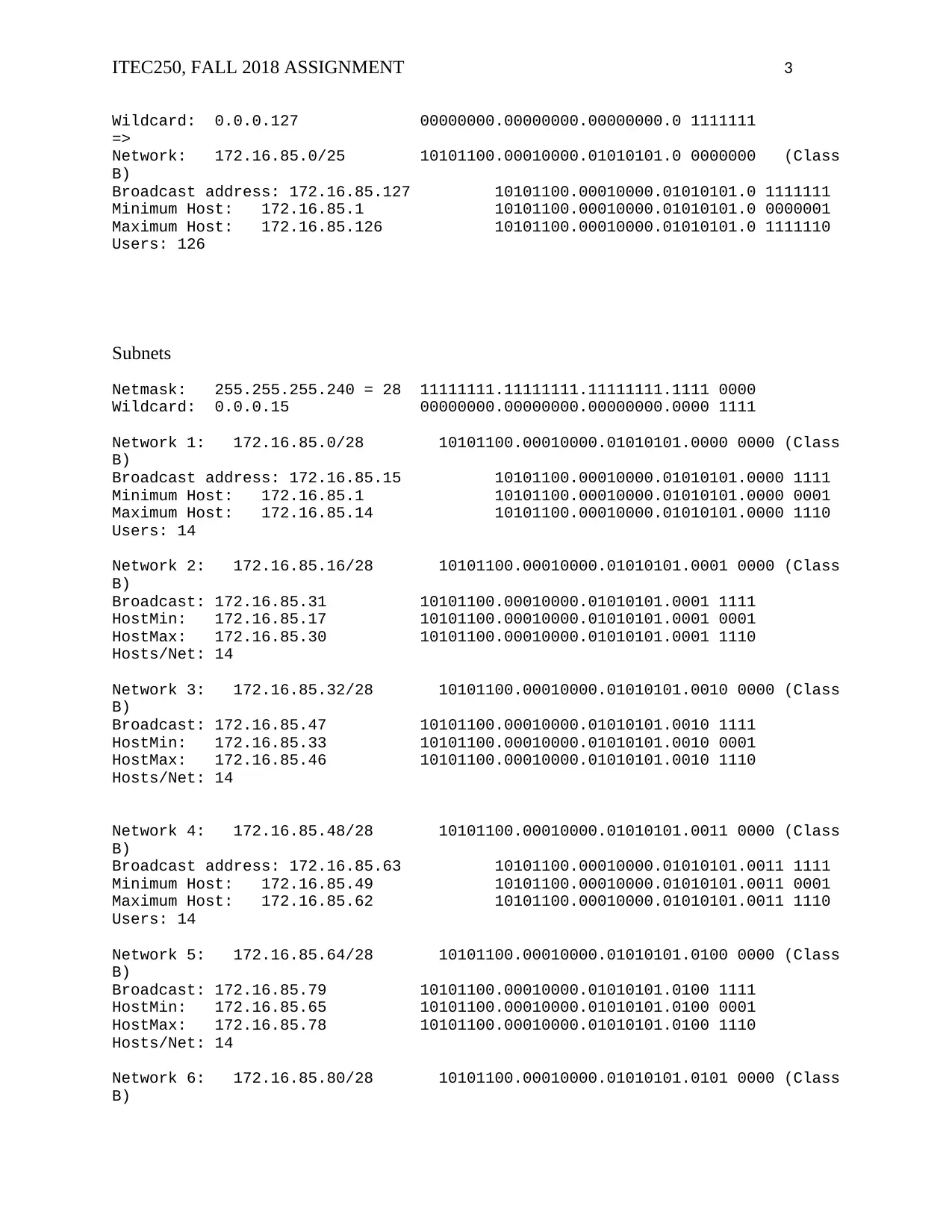
Wildcard: 0.0.0.127 00000000.00000000.00000000.0 1111111
=>
Network: 172.16.85.0/25 10101100.00010000.01010101.0 0000000 (Class
B)
Broadcast address: 172.16.85.127 10101100.00010000.01010101.0 1111111
Minimum Host: 172.16.85.1 10101100.00010000.01010101.0 0000001
Maximum Host: 172.16.85.126 10101100.00010000.01010101.0 1111110
Users: 126
Subnets
Netmask: 255.255.255.240 = 28 11111111.11111111.11111111.1111 0000
Wildcard: 0.0.0.15 00000000.00000000.00000000.0000 1111
Network 1: 172.16.85.0/28 10101100.00010000.01010101.0000 0000 (Class
B)
Broadcast address: 172.16.85.15 10101100.00010000.01010101.0000 1111
Minimum Host: 172.16.85.1 10101100.00010000.01010101.0000 0001
Maximum Host: 172.16.85.14 10101100.00010000.01010101.0000 1110
Users: 14
Network 2: 172.16.85.16/28 10101100.00010000.01010101.0001 0000 (Class
B)
Broadcast: 172.16.85.31 10101100.00010000.01010101.0001 1111
HostMin: 172.16.85.17 10101100.00010000.01010101.0001 0001
HostMax: 172.16.85.30 10101100.00010000.01010101.0001 1110
Hosts/Net: 14
Network 3: 172.16.85.32/28 10101100.00010000.01010101.0010 0000 (Class
B)
Broadcast: 172.16.85.47 10101100.00010000.01010101.0010 1111
HostMin: 172.16.85.33 10101100.00010000.01010101.0010 0001
HostMax: 172.16.85.46 10101100.00010000.01010101.0010 1110
Hosts/Net: 14
Network 4: 172.16.85.48/28 10101100.00010000.01010101.0011 0000 (Class
B)
Broadcast address: 172.16.85.63 10101100.00010000.01010101.0011 1111
Minimum Host: 172.16.85.49 10101100.00010000.01010101.0011 0001
Maximum Host: 172.16.85.62 10101100.00010000.01010101.0011 1110
Users: 14
Network 5: 172.16.85.64/28 10101100.00010000.01010101.0100 0000 (Class
B)
Broadcast: 172.16.85.79 10101100.00010000.01010101.0100 1111
HostMin: 172.16.85.65 10101100.00010000.01010101.0100 0001
HostMax: 172.16.85.78 10101100.00010000.01010101.0100 1110
Hosts/Net: 14
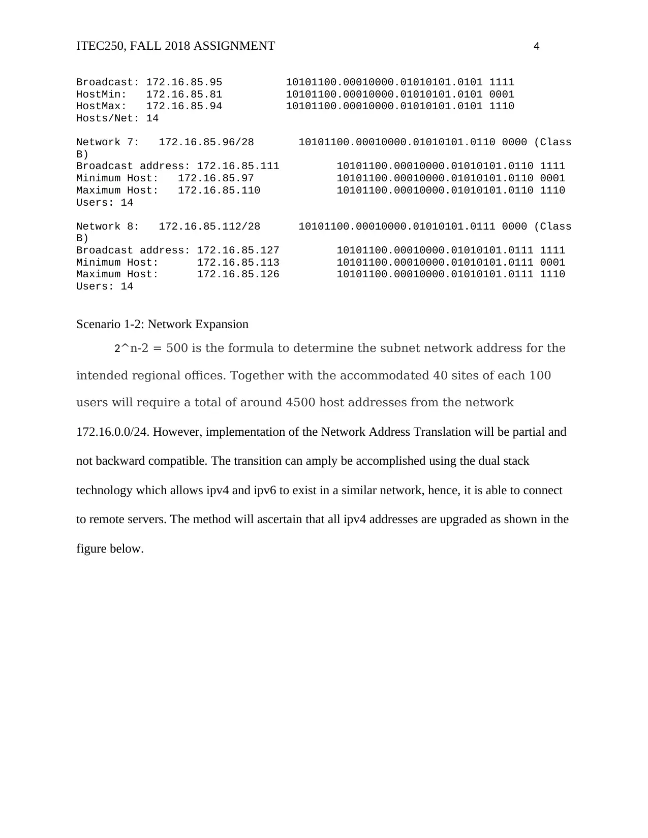
Network 6: 172.16.85.80/28 10101100.00010000.01010101.0101 0000 (Class
B)
ITEC250, FALL 2018 ASSIGNMENT 4
Broadcast: 172.16.85.95 10101100.00010000.01010101.0101 1111
HostMin: 172.16.85.81 10101100.00010000.01010101.0101 0001
HostMax: 172.16.85.94 10101100.00010000.01010101.0101 1110
Hosts/Net: 14
Network 7: 172.16.85.96/28 10101100.00010000.01010101.0110 0000 (Class
B)
Broadcast address: 172.16.85.111 10101100.00010000.01010101.0110 1111
Minimum Host: 172.16.85.97 10101100.00010000.01010101.0110 0001
Maximum Host: 172.16.85.110 10101100.00010000.01010101.0110 1110
Users: 14
Network 8: 172.16.85.112/28 10101100.00010000.01010101.0111 0000 (Class
B)
Broadcast address: 172.16.85.127 10101100.00010000.01010101.0111 1111
Minimum Host: 172.16.85.113 10101100.00010000.01010101.0111 0001
Maximum Host: 172.16.85.126 10101100.00010000.01010101.0111 1110
Users: 14
Scenario 1-2: Network Expansion
2^n-2 = 500 is the formula to determine the subnet network address for the
intended regional offices. Together with the accommodated 40 sites of each 100
users will require a total of around 4500 host addresses from the network
172.16.0.0/24. However, implementation of the Network Address Translation will be partial and
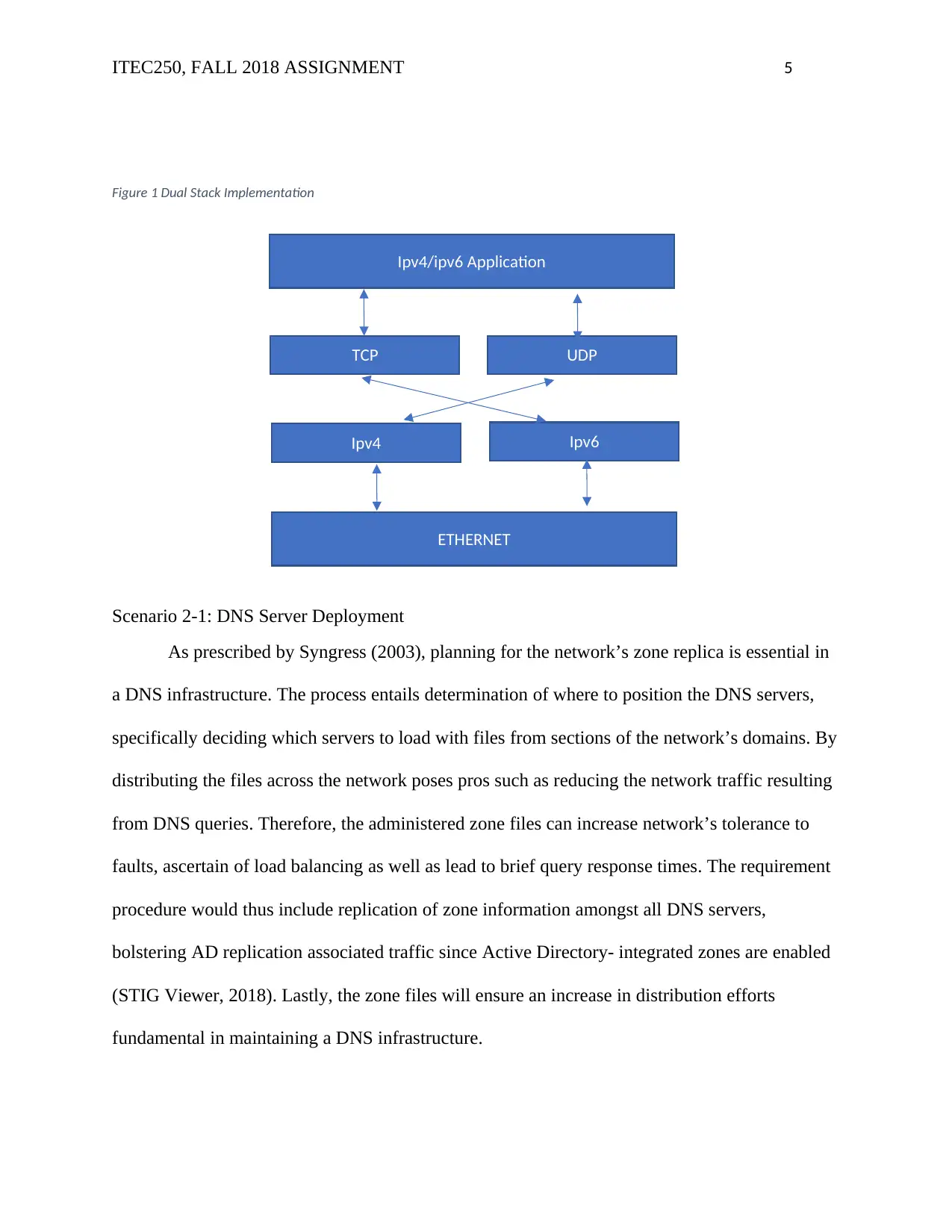
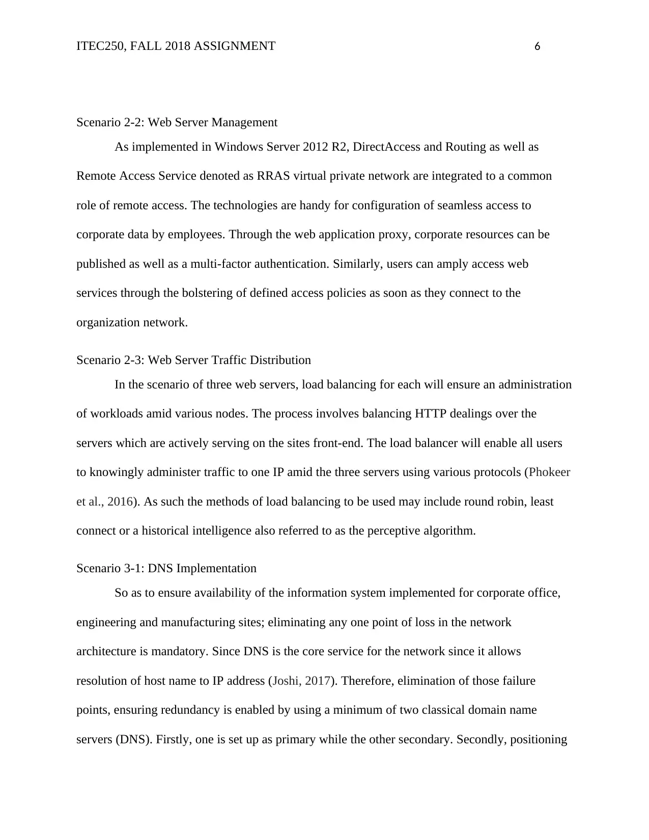
not backward compatible. The transition can amply be accomplished using the dual stack
technology which allows ipv4 and ipv6 to exist in a similar network, hence, it is able to connect
to remote servers. The method will ascertain that all ipv4 addresses are upgraded as shown in the
figure below.
Secure Best Marks with AI Grader
Need help grading? Try our AI Grader for instant feedback on your assignments.
ITEC250, FALL 2018 ASSIGNMENT 5
Figure 1 Dual Stack Implementation
Scenario 2-1: DNS Server Deployment
As prescribed by Syngress (2003), planning for the network’s zone replica is essential in
a DNS infrastructure. The process entails determination of where to position the DNS servers,
specifically deciding which servers to load with files from sections of the network’s domains. By
distributing the files across the network poses pros such as reducing the network traffic resulting
from DNS queries. Therefore, the administered zone files can increase network’s tolerance to
faults, ascertain of load balancing as well as lead to brief query response times. The requirement
procedure would thus include replication of zone information amongst all DNS servers,
bolstering AD replication associated traffic since Active Directory- integrated zones are enabled
(STIG Viewer, 2018). Lastly, the zone files will ensure an increase in distribution efforts
fundamental in maintaining a DNS infrastructure.
Ipv4/ipv6 Application
ETHERNET
TCP
Ipv6Ipv4
UDP
ITEC250, FALL 2018 ASSIGNMENT 6
Scenario 2-2: Web Server Management
As implemented in Windows Server 2012 R2, DirectAccess and Routing as well as
Remote Access Service denoted as RRAS virtual private network are integrated to a common
role of remote access. The technologies are handy for configuration of seamless access to
corporate data by employees. Through the web application proxy, corporate resources can be
published as well as a multi-factor authentication. Similarly, users can amply access web
services through the bolstering of defined access policies as soon as they connect to the
organization network.
Scenario 2-3: Web Server Traffic Distribution
In the scenario of three web servers, load balancing for each will ensure an administration
of workloads amid various nodes. The process involves balancing HTTP dealings over the
servers which are actively serving on the sites front-end. The load balancer will enable all users
to knowingly administer traffic to one IP amid the three servers using various protocols (Phokeer
et al., 2016). As such the methods of load balancing to be used may include round robin, least
connect or a historical intelligence also referred to as the perceptive algorithm.
Scenario 3-1: DNS Implementation
So as to ensure availability of the information system implemented for corporate office,
engineering and manufacturing sites; eliminating any one point of loss in the network
architecture is mandatory. Since DNS is the core service for the network since it allows
resolution of host name to IP address (Joshi, 2017). Therefore, elimination of those failure
points, ensuring redundancy is enabled by using a minimum of two classical domain name
servers (DNS). Firstly, one is set up as primary while the other secondary. Secondly, positioning
ITEC250, FALL 2018 ASSIGNMENT 7
of the servers can be made on different subnets of the network as well as a different physical
condition.
Scenario 3-2: DNS Updates Manipulation
Manual maintenance of DNS records is challenging thence the need for dynamic DNS
updating using Microsoft DNS server. However, caution is taken so as to ensure safety in the
process. A secure update of static DNS records mandates for a limitation among users authorized
through rights to update. Dynamic DNS records which are formed by DNS systems on behalf of
users allows updates with minimal efforts of maintaining DNS zones (Faccin et al., 2014). The
configurations can be done in three separate ways including
None – only allows static management or records.
Non-secure and secure allow for dynamic updates without need to check if source is
trusted or not.
Secure only are dynamic updates that emanate for only trusted sources and is present for
primary DNS zone as an AD-integrated DNS zone hosted on a Domain Controller.
Scenario 3-3: Time To Live (TTL) Configuration in DNS
Regarded as the hop limit in ipv6, Time-to-live (TTL) is an IP packet that instructs the
router on the packets duration on the network. It is initially set by the sender system and could be
set amid values 1 and 255 depending on the operating system, each having its default value.
Using BIND resource records, explicit TTL values are allowed to override the area file’s TTL for
the particular record (McHenry, 2018). The latter is implemented to prevent non-classical servers
from hoarding the records as a preliminary change of the server’s IP.
Paraphrase This Document
Need a fresh take? Get an instant paraphrase of this document with our AI Paraphraser
ITEC250, FALL 2018 ASSIGNMENT 8
References
Faccin, S., Purnadi, R., Hulkkonen, T., Rajaniemi, J., Tuohino, M., & Sivanandan, M.
(2014). U.S. Patent No. 8,862,751. Washington, DC: U.S. Patent and Trademark Office.
Joshi, P. S. (2017). U.S. Patent No. 9,584,360. Washington, DC: U.S. Patent and Trademark
Office.
McHenry, Q. (2018). DNS/BIND: set TTL for individual resource records. Retrieved from
https://www.tech-recipes.com/rx/310/dnsbind-set-ttl-for-individual-resource-records/
Phokeer, A., Aina, A., & Johnson, D. (2016, December). DNS Lame delegations: A case-study
of public reverse DNS records in the African Region. In International Conference on e-
Infrastructure and e-Services for Developing Countries (pp. 232-242). Springer, Cham.
Syngress, S. (2003). MCSE Planning and Maintaining a Microsoft Windows Server 2003
Network Infrastructure (Exam 70-293). Elsevier Science.
STIG Viewer | Unified Compliance Framework®. (2018). The DNS implementation must be
fault-tolerant.. [online] Available at:
https://www.stigviewer.com/stig/domain_name_system_dns_security_requirements_guid
e/2012-10-24/finding/V-34261 [Accessed 17 Oct. 2018].
1 out of 8
Related Documents
Your All-in-One AI-Powered Toolkit for Academic Success.
+13062052269
info@desklib.com
Available 24*7 on WhatsApp / Email
![[object Object]](/_next/static/media/star-bottom.7253800d.svg)
Unlock your academic potential
© 2024 | Zucol Services PVT LTD | All rights reserved.


