Mechanical Engineering Lab Report: Refrigeration Cycle Analysis
VerifiedAdded on 2020/05/28
|11
|1996
|2095
Report
AI Summary
This lab report details an experiment investigating the vapour-compression refrigeration cycle using a Hilton Refrigeration rig and refrigerant R134a. The experiment aimed to study the refrigeration process, identify the state and phase changes of the refrigerant, determine energy transfers, and calculate the coefficient of performance (COP). The report includes descriptions of the experimental setup, methods, and results, which were obtained by varying the evaporator load while keeping the condenser pressure constant. Data collected includes temperatures, pressures, flow rates, and power inputs. Calculations were performed to determine enthalpies and COPs. The results indicate that increasing the evaporator load leads to higher compressor temperatures and evaporator pressures. The report concludes with a discussion of the findings, observed irregularities, and potential sources of error, such as maintaining a constant condenser pressure. Appendices provide calculated COP values and relevant graphs.
LAB REPORT
Name of Student
Institution Affiliation
1
Name of Student
Institution Affiliation
1
Paraphrase This Document
Need a fresh take? Get an instant paraphrase of this document with our AI Paraphraser
Introduction
The experiment which was carried out aimed studying the Vapour-compression
refrigeration. Both Hilton Refrigeration and the refrigerant R134a were used in during the
session. Refrigeration refers to the process of taking heat from a reservoir with low
temperatures then dumped to another reservoir with high temperatures to ensure that a
cold space is always available in the system.
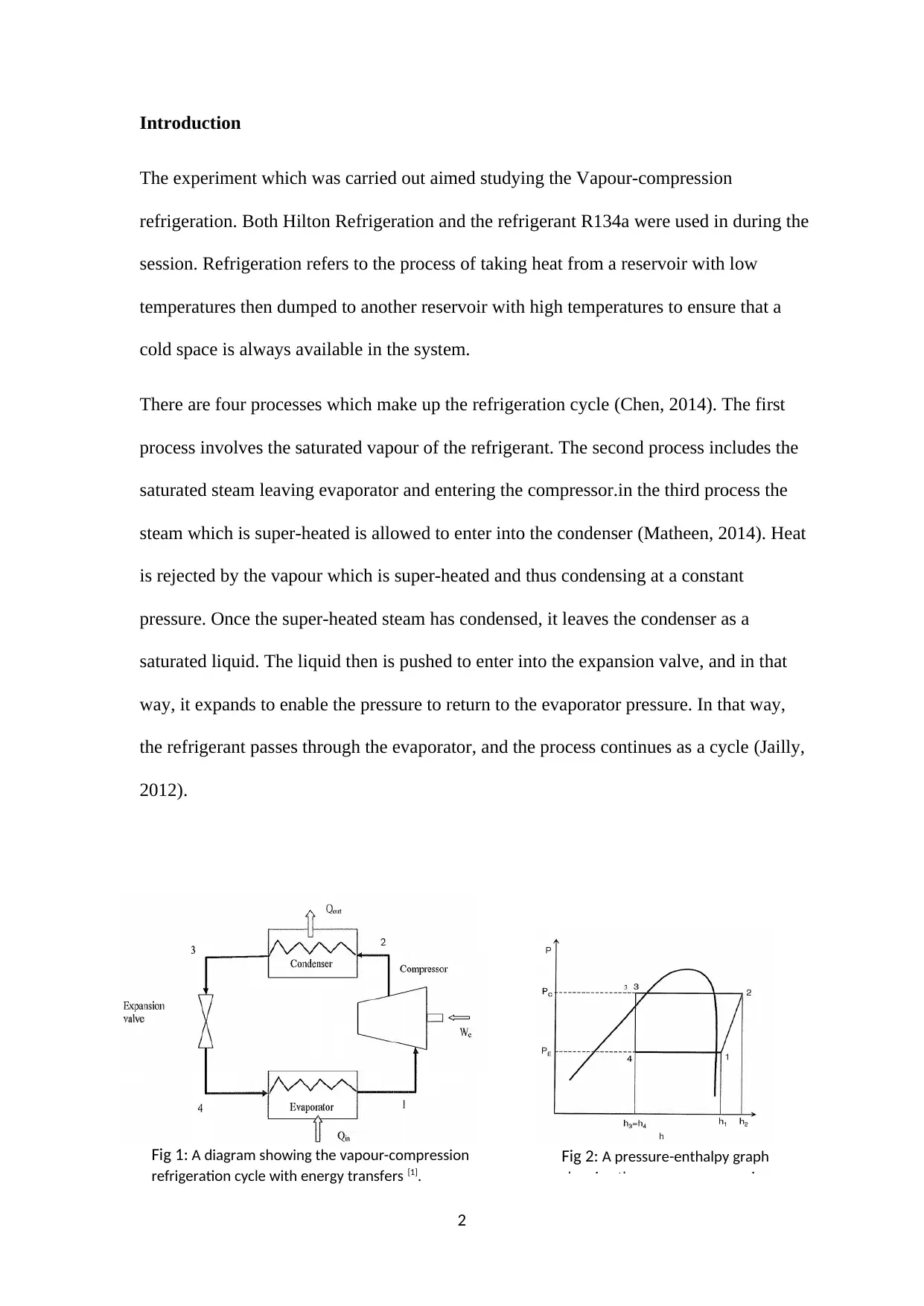
There are four processes which make up the refrigeration cycle (Chen, 2014). The first
process involves the saturated vapour of the refrigerant. The second process includes the
saturated steam leaving evaporator and entering the compressor.in the third process the
steam which is super-heated is allowed to enter into the condenser (Matheen, 2014). Heat
is rejected by the vapour which is super-heated and thus condensing at a constant
pressure. Once the super-heated steam has condensed, it leaves the condenser as a
saturated liquid. The liquid then is pushed to enter into the expansion valve, and in that
way, it expands to enable the pressure to return to the evaporator pressure. In that way,
the refrigerant passes through the evaporator, and the process continues as a cycle (Jailly,
2012).
2
Fig 1: A diagram showing the vapour-compression
refrigeration cycle with energy transfers [1].
Fig 2: A pressure-enthalpy graph
showing the vapour-compression
By Appling the first law of thermodynamics in the systems which are open.
Q+W =ṁ( (h2−h1 ) +1
2 (c2
2−c1
2)+ g ( z2−z1 ) )
Objectives
The objectives of the experiment which was carried out were: to identify the phase and
state of refrigerant as it goes through the processes of the evaporator, compressor, throttle
valve and the condenser. To find out the energy which is transferred to all the systems
which are mentioned above. To calculate the coefficient of performance of the
refrigeration (Mojinin, 2010).
Experiment Set-Up
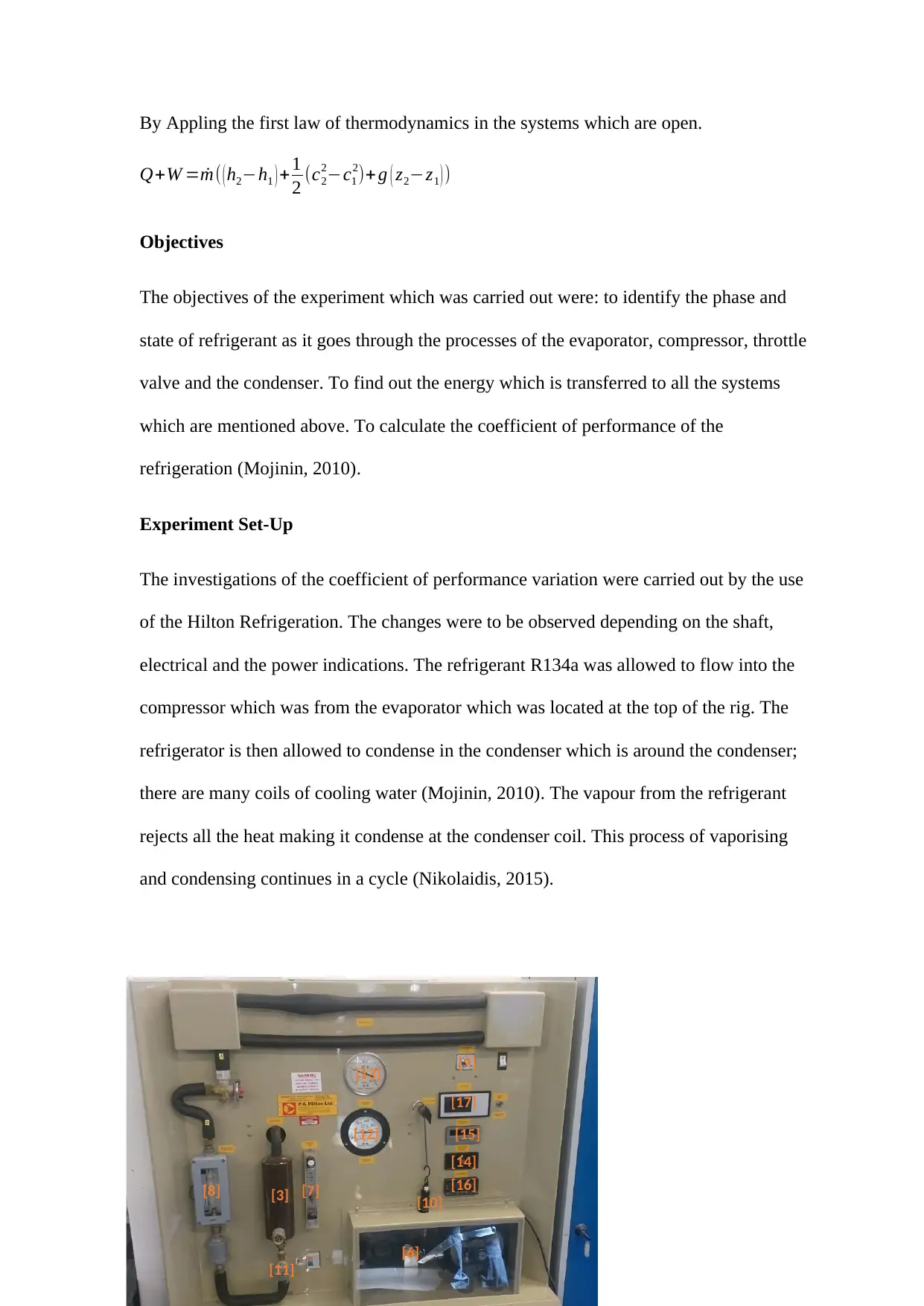
The investigations of the coefficient of performance variation were carried out by the use
of the Hilton Refrigeration. The changes were to be observed depending on the shaft,
electrical and the power indications. The refrigerant R134a was allowed to flow into the
compressor which was from the evaporator which was located at the top of the rig. The
refrigerator is then allowed to condense in the condenser which is around the condenser;
there are many coils of cooling water (Mojinin, 2010). The vapour from the refrigerant
rejects all the heat making it condense at the condenser coil. This process of vaporising
and condensing continues in a cycle (Nikolaidis, 2015).
3
[17]
[16]
[15]
[14]
[13]
[12]
[11]
[10]
[8] [7]
[6]
[9]
[3]
⊘ This is a preview!⊘
Do you want full access?
Subscribe today to unlock all pages.

Trusted by 1+ million students worldwide
Method
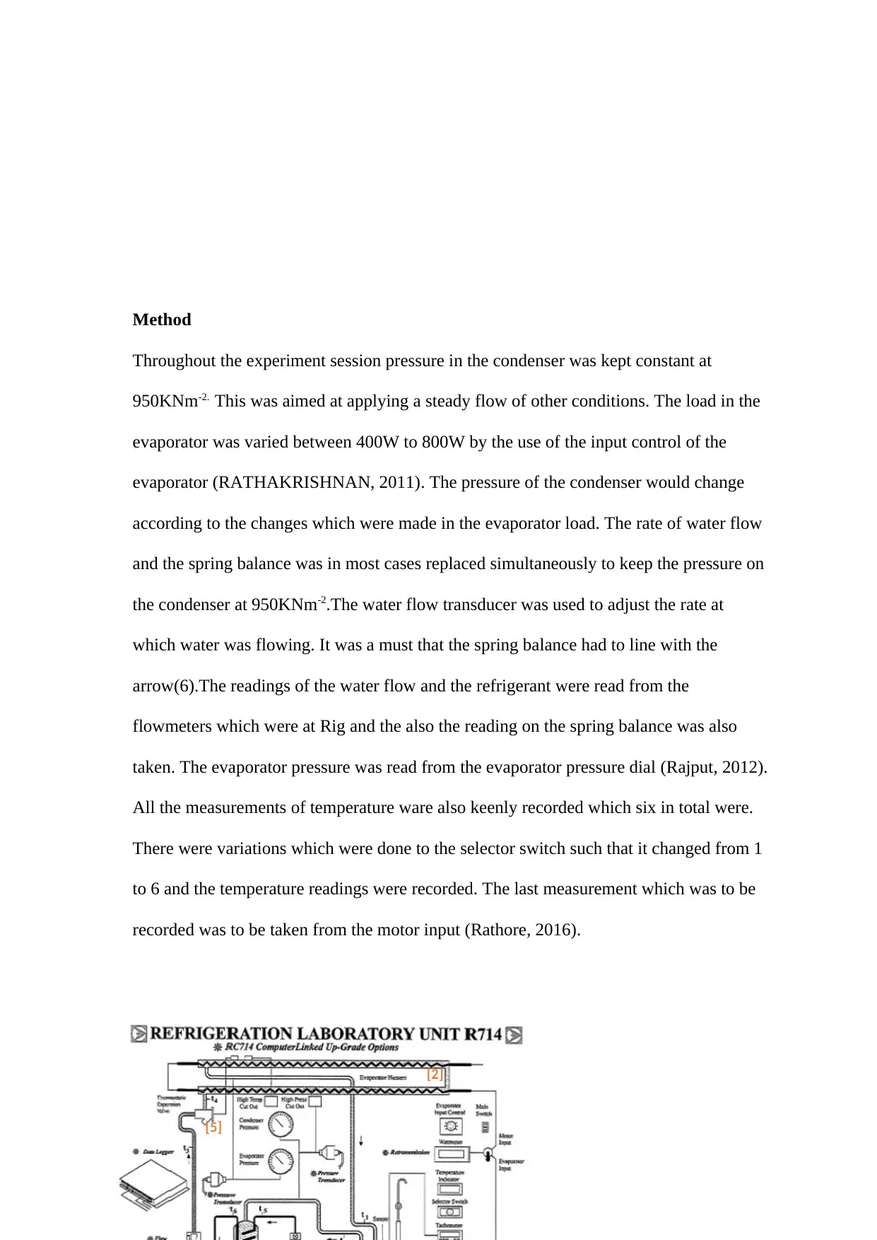
Throughout the experiment session pressure in the condenser was kept constant at
950KNm-2. This was aimed at applying a steady flow of other conditions. The load in the
evaporator was varied between 400W to 800W by the use of the input control of the
evaporator (RATHAKRISHNAN, 2011). The pressure of the condenser would change
according to the changes which were made in the evaporator load. The rate of water flow
and the spring balance was in most cases replaced simultaneously to keep the pressure on
the condenser at 950KNm-2.The water flow transducer was used to adjust the rate at
which water was flowing. It was a must that the spring balance had to line with the
arrow(6).The readings of the water flow and the refrigerant were read from the
flowmeters which were at Rig and the also the reading on the spring balance was also
taken. The evaporator pressure was read from the evaporator pressure dial (Rajput, 2012).
All the measurements of temperature ware also keenly recorded which six in total were.
There were variations which were done to the selector switch such that it changed from 1
to 6 and the temperature readings were recorded. The last measurement which was to be
recorded was to be taken from the motor input (Rathore, 2016).
4
[5]
[2]
Paraphrase This Document
Need a fresh take? Get an instant paraphrase of this document with our AI Paraphraser
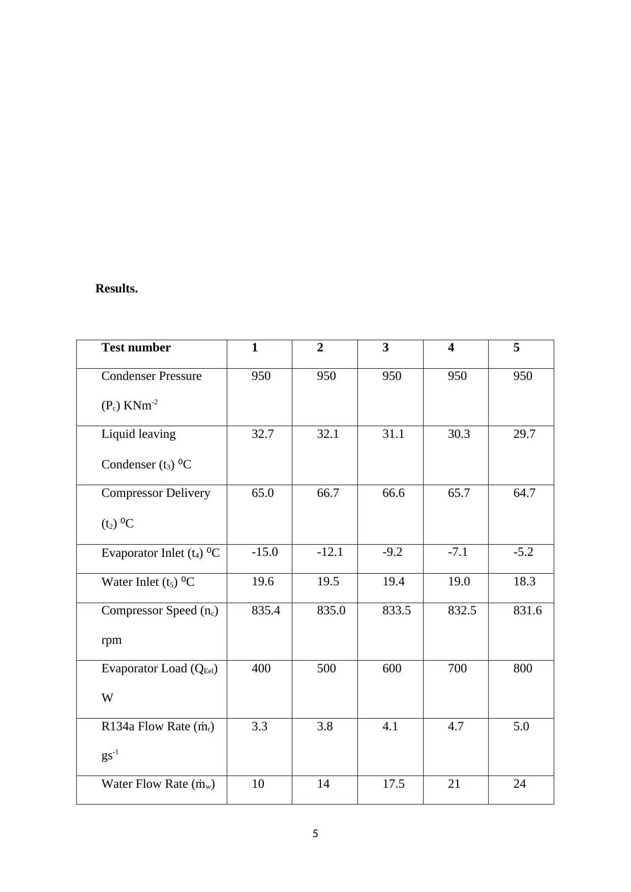
Results.
Test number 1 2 3 4 5
Condenser Pressure
(Pc) KNm-2
950 950 950 950 950
Liquid leaving
Condenser (t3) ⁰C
32.7 32.1 31.1 30.3 29.7
Compressor Delivery
(t2) ⁰C
65.0 66.7 66.6 65.7 64.7
Evaporator Inlet (t4) ⁰C -15.0 -12.1 -9.2 -7.1 -5.2
Water Inlet (t5) ⁰C 19.6 19.5 19.4 19.0 18.3
Compressor Speed (nc)
rpm
835.4 835.0 833.5 832.5 831.6
Evaporator Load (QEel)
W
400 500 600 700 800
R134a Flow Rate (ṁr)
gs-1
3.3 3.8 4.1 4.7 5.0
Water Flow Rate (ṁw) 10 14 17.5 21 24
5
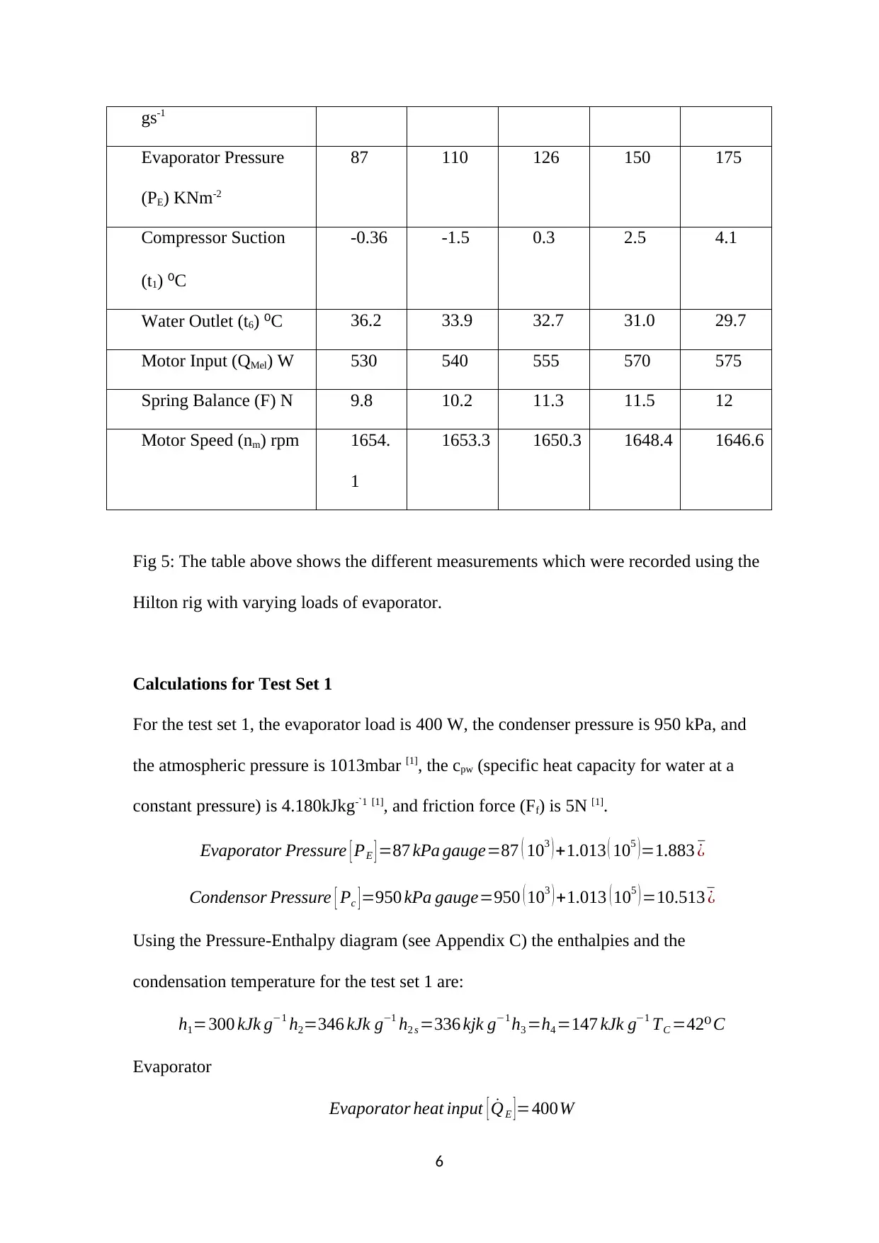
gs-1
Evaporator Pressure
(PE) KNm-2
87 110 126 150 175
Compressor Suction
(t1) ⁰C
-0.36 -1.5 0.3 2.5 4.1
Water Outlet (t6) ⁰C 36.2 33.9 32.7 31.0 29.7
Motor Input (QMel) W 530 540 555 570 575
Spring Balance (F) N 9.8 10.2 11.3 11.5 12
Motor Speed (nm) rpm 1654.
1
1653.3 1650.3 1648.4 1646.6
Fig 5: The table above shows the different measurements which were recorded using the
Hilton rig with varying loads of evaporator.
Calculations for Test Set 1
For the test set 1, the evaporator load is 400 W, the condenser pressure is 950 kPa, and
the atmospheric pressure is 1013mbar [1], the cpw (specific heat capacity for water at a
constant pressure) is 4.180kJkg-`1 [1], and friction force (Ff) is 5N [1].
Evaporator Pressure [ PE ] =87 kPa gauge=87 ( 103 ) +1.013 ( 105 )=1.883 ¯¿
Condensor Pressure [ Pc ] =950 kPa gauge=950 ( 103 ) +1.013 ( 105 ) =10.513¯¿
Using the Pressure-Enthalpy diagram (see Appendix C) the enthalpies and the
condensation temperature for the test set 1 are:
h1=300 kJk g−1 h2=346 kJk g−1 h2 s =336 kjk g−1 h3 =h4 =147 kJk g−1 TC =42⁰C
Evaporator
Evaporator heat input [ ˙QE ] =400W
6
⊘ This is a preview!⊘
Do you want full access?
Subscribe today to unlock all pages.

Trusted by 1+ million students worldwide
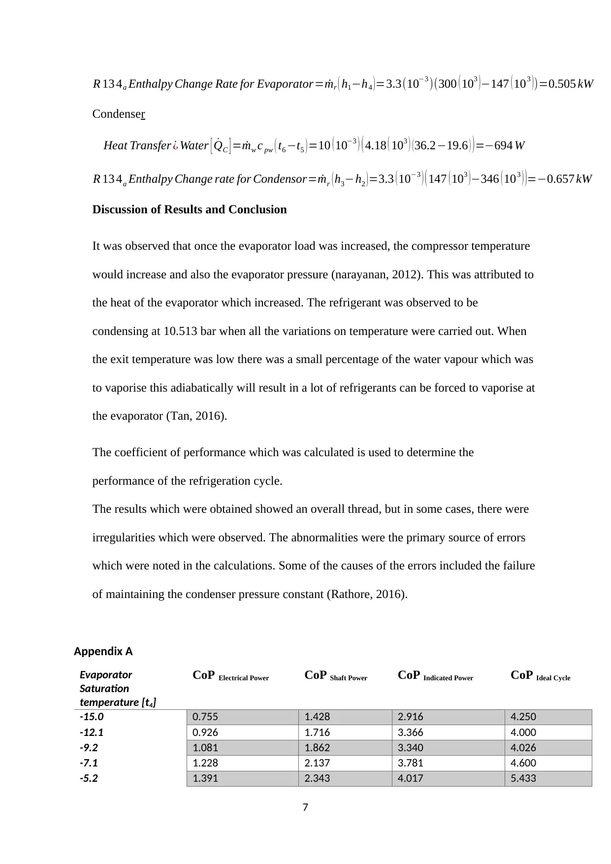
R 13 4a Enthalpy Change Rate for Evaporator=ṁr ( h1−h4 ) =3.3(10−3 )(300 ( 103 )−147 ( 103 ))=0.505 kW
Condenser
Heat Transfer ¿ Water [ ˙QC ] =ṁw c pw ( t6 −t5 ) =10 ( 10−3 ) ( 4.18 ( 103 ) ( 36.2−19.6 ) ) =−694 W
R 13 4a Enthalpy Change rate for Condensor=ṁr ( h3−h2 ) =3.3 ( 10−3 ) ( 147 ( 103 ) −346 ( 103 ) )=−0.657 kW
Discussion of Results and Conclusion
It was observed that once the evaporator load was increased, the compressor temperature
would increase and also the evaporator pressure (narayanan, 2012). This was attributed to
the heat of the evaporator which increased. The refrigerant was observed to be
condensing at 10.513 bar when all the variations on temperature were carried out. When
the exit temperature was low there was a small percentage of the water vapour which was
to vaporise this adiabatically will result in a lot of refrigerants can be forced to vaporise at
the evaporator (Tan, 2016).
The coefficient of performance which was calculated is used to determine the
performance of the refrigeration cycle.
The results which were obtained showed an overall thread, but in some cases, there were
irregularities which were observed. The abnormalities were the primary source of errors
which were noted in the calculations. Some of the causes of the errors included the failure
of maintaining the condenser pressure constant (Rathore, 2016).
Appendix A
Evaporator
Saturation
temperature [t4]
CoP Electrical Power CoP Shaft Power CoP Indicated Power CoP Ideal Cycle
-15.0 0.755 1.428 2.916 4.250
-12.1 0.926 1.716 3.366 4.000
-9.2 1.081 1.862 3.340 4.026
-7.1 1.228 2.137 3.781 4.600
-5.2 1.391 2.343 4.017 5.433
7
Paraphrase This Document
Need a fresh take? Get an instant paraphrase of this document with our AI Paraphraser
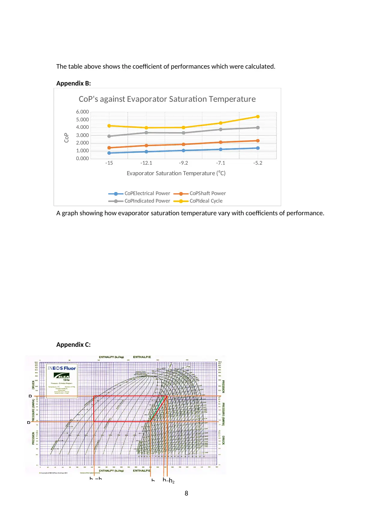
The table above shows the coefficient of performances which were calculated.
Appendix B:
A graph showing how evaporator saturation temperature vary with coefficients of performance.
Appendix C:
8
-15 -12.1 -9.2 -7.1 -5.2
0.000
1.000
2.000
3.000
4.000
5.000
6.000
CoP's against Evaporator Saturation Temperature
CoPElectrical Power CoPShaft Power
CoPIndicated Power CoPIdeal Cycle
Evaporator Saturation Temperature (⁰C)
CoP
h2h2Sh1
h3=h4
PE
P
Pressure – Enthalpy diagram showing the refrigeration cycle at an evaporator load of 400W.the
enthalpies at each stage are shown by the orange lines. For the case of the green lines they are
used to show the entropy lines which are used to find h2S.the test 1 for refrigeration cycle are
shown by the red lines.
References
Megaritis T, Ganippa L. Thermal Power Systems [Internet]. 1st ed. [cited 19 December
2014]. Available from: https://blackboard.brunel.ac.uk/bbcswebdav/pid-465152-dt-content-
rid-1439146_1/courses/C.ME2301.A.2014-5.YEAR/Thanos%20Lionel%20Thermo
%20Labs/ME2301%20Thermo%20Labs.pdf
Hundy J. Vapour Compression Cycle - Understanding Refrigeration [Internet].
Alephzero.co.uk. 2015 [cited 19 December 2014]. Available from:
http://www.alephzero.co.uk/ref/vapcomcyc.htm
TheFreeDictionary.com. Clausius' statement [Internet]. 2015 [cited 19 December 2014].
Available from: http://encyclopedia2.thefreedictionary.com/Clausius%27+statement
9
⊘ This is a preview!⊘
Do you want full access?
Subscribe today to unlock all pages.

Trusted by 1+ million students worldwide
Kirby R. The First Law of Thermodynamics: Open Systems [Internet]. 1st ed. [cited 19
December 2014]. Available from: https://blackboard.brunel.ac.uk/bbcswebdav/pid-309953-
dt-content-rid-915291_1/courses/C.ME1301.A.2013-4.YEAR/Section%205.pdf
Refrigeration Laboratory Unit R714 [Internet]. 1st ed. 2015 [cited 19 December 2014].
Available from: http://fichas.prodel.es/termodinamica/R714.pdf
Baratuci W. Ch4, Lesson F, Page 9 - Coefficient of Performance for a Refrigeration Cycle
[Internet]. Learnthermo.com. 2015 [cited 2 January 2015]. Available from:
http://www.learnthermo.com/T1-tutorial/ch04/lesson-F/pg09.php
Achrnews.com. Condensing Temperature Clues [Internet]. 2004 [cited 2 January 2015].
Available from: http://www.achrnews.com/articles/91476-condensing-temperature-clues
AMEEN, A. (2013). REFRIGERATION AND AIR CONDITIONING. Chicago: PHI Learning
Pvt. Ltd.
Chen, Q. (2014). Performance Comparison and Analysis of Vapour-compression
Refrigeration Systems Using CFC12 and Ozone-safe Refrigerant HFC134a. London:
University of New Brunswick, Department of Mechanical Engineering.
Jailly, R. (2012). Performance Characteristics of Vapour Compression Refrigeration Cycle
Using Different Type of Expansion Valve. London: Universiti Teknologi Malaysia.
Matheen, P. A. (2014). Heat Transfer Laboratory Manual. Chicago: Firewall Media.
Mojinin, M. (2010). Simultaneous Heating and Cooling Using a Vapour-compression
Refrigeration Machine. Paris: Jabatan Kejuruteraan Mekanik, Fakulti Kejuruteraan,
Universiti Malaya.
narayanan, A. (2012). Basic Refrigeration and Air Conditioning. Sydney: Tata McGraw-Hill
Education.
10
Paraphrase This Document
Need a fresh take? Get an instant paraphrase of this document with our AI Paraphraser
Nikolaidis, C. (2015). A Computer Study of Multi-stage Vapour Compression Refrigeration
Cycles by the Exergy Method. Texas: University of London,.
Rajput, R. K. (2012). A Textbook of Engineering Thermodynamics. Chicago: Firewall Media.
RATHAKRISHNAN, E. (2011). FUNDAMENTALS OF ENGINEERING
THERMODYNAMICS. Texas: PHI Learning Pvt. Ltd.
Rathore, M. M. (2016). Thermal Engineering. Berlin: Tata McGraw-Hill Education.
Tan, C. S. (2016). Computer Software Simulation for a Vapour Compression Refrigeration
Cycle. Chicago: Fakulti Kejuruteraan, Universiti Malaya.
11
1 out of 11
Related Documents
Your All-in-One AI-Powered Toolkit for Academic Success.
+13062052269
info@desklib.com
Available 24*7 on WhatsApp / Email
![[object Object]](/_next/static/media/star-bottom.7253800d.svg)
Unlock your academic potential
Copyright © 2020–2025 A2Z Services. All Rights Reserved. Developed and managed by ZUCOL.


