University Name: I-Beam Lateral Torsional Buckling Analysis Report
VerifiedAdded on 2022/09/09
|12
|1089
|32
Report
AI Summary
This report presents a comprehensive analysis of the lateral torsional buckling behavior of I-beams under concentrated loads. The study utilizes the finite element method, employing Abaqus software to model and simulate three different I-beam cross-sections. The report details the model setup, including dimensions, meshing, applied loads, and boundary conditions. Analytical solutions are also provided for comparison. The results section includes displacement and stress plots for each cross-section, alongside a comparison of their load-carrying capacities. It is observed that the beam with the thickest center flange exhibits the highest buckling load. The report concludes by comparing analytical and numerical results and summarizing the key findings regarding the influence of cross-sectional geometry on buckling strength. The report also provides load-displacement curves for all three I-beam cross-sections.
Lateral Torsional Buckling analysis of an I-Beam
<Student Name>
<Student Number>
Assignment Report
Supervisor: <XXX>
Department Name
University Name
<Month Year>
<Student Name>
<Student Number>
Assignment Report
Supervisor: <XXX>
Department Name
University Name
<Month Year>
Paraphrase This Document
Need a fresh take? Get an instant paraphrase of this document with our AI Paraphraser
ABSTRACT
In the current study, 3 different cross-sections of I-Beam are studied and compared for their
performance at different I-cross sections. The 3 cross-sections chosen are based on the standard
dimensions that are available off the shelf. The center thickness of the I-beam plays a significant
role in limiting the torsional bucking of the beam. It is shown in the analysis in current study that
thickest section has highest rigidity for buckling and hence loads are higher.
i
TABLE OF CONTENTS
ABSTRACT......................................................................................................................................i
TABLE OF CONTENTS.................................................................................................................ii
CHAPTER I: INTRODUCTION.....................................................................................................1
CHAPTER II: Model Set-up, Dimensions and Boundary conditions.............................................2
Beam Cross-section......................................................................................................................2
Meshing, Loads and Boundary conditions...............................................................................3
Analytical Solution..................................................................................................................4
CHAPTER III: Results & Discussion..............................................................................................5
CHAPTER IV: Conclusion..............................................................................................................9
ii
⊘ This is a preview!⊘
Do you want full access?
Subscribe today to unlock all pages.

Trusted by 1+ million students worldwide
CHAPTER I: INTRODUCTION
Different beam cross-sections provide different strengths based on their usage and use. I-beam
cross-section are considered to be providing highest strength to weight ratio. The beams deforms
laterally under the application of concentrated load on the beam. If the lateral deformation of the
beam is constrained, it might lead to lateral torsional buckling.
In the current study, a simply supported beam is modelled in Abaqus software which is a
commercial finite element modelling software. The chosen cross-section and obtained results are
chosen in the subsequent section.
1
Paraphrase This Document
Need a fresh take? Get an instant paraphrase of this document with our AI Paraphraser
CHAPTER II: Model Set-up, Dimensions and Boundary conditions
In the current section, the modelled geometry, meshing, loads and boundary conditions are
discussed as applied in Abaqus software.
Beam Cross-section
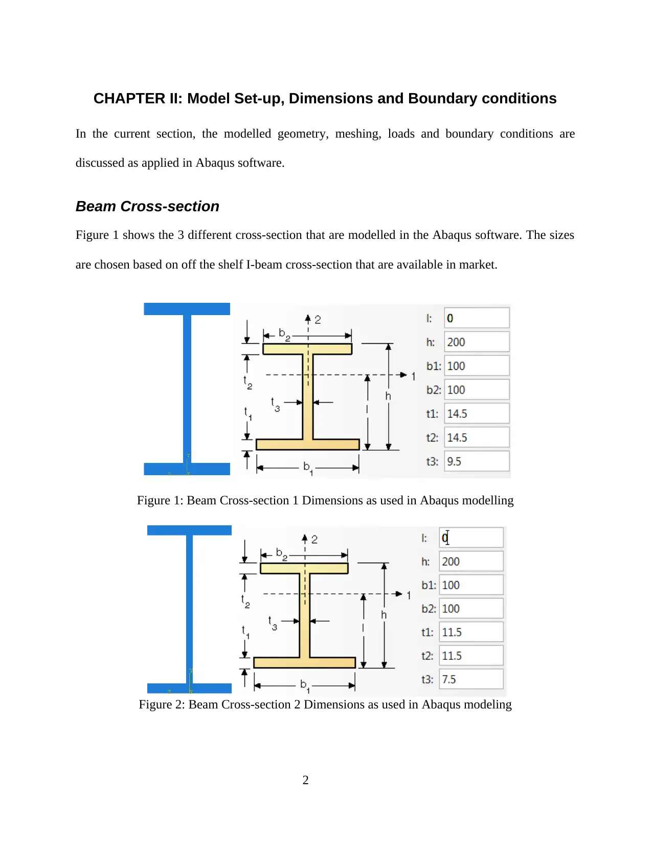
Figure 1 shows the 3 different cross-section that are modelled in the Abaqus software. The sizes
are chosen based on off the shelf I-beam cross-section that are available in market.
Figure 1: Beam Cross-section 1 Dimensions as used in Abaqus modelling
Figure 2: Beam Cross-section 2 Dimensions as used in Abaqus modeling
2
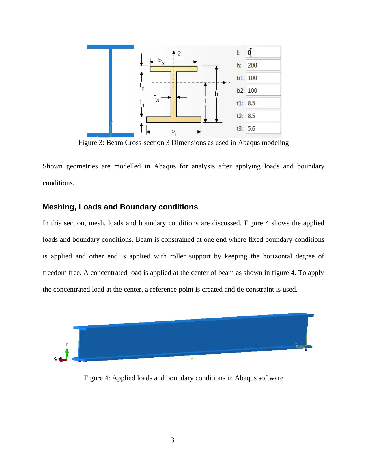
Figure 3: Beam Cross-section 3 Dimensions as used in Abaqus modeling
Shown geometries are modelled in Abaqus for analysis after applying loads and boundary
conditions.
Meshing, Loads and Boundary conditions
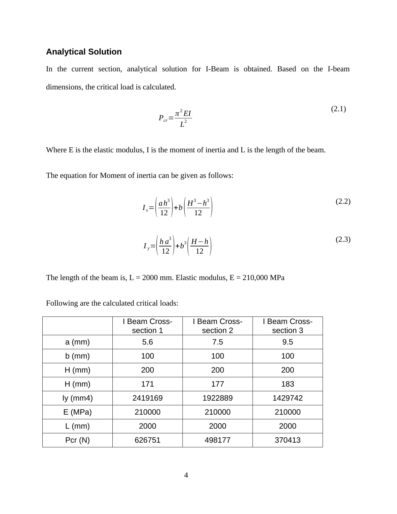
In this section, mesh, loads and boundary conditions are discussed. Figure 4 shows the applied
loads and boundary conditions. Beam is constrained at one end where fixed boundary conditions
is applied and other end is applied with roller support by keeping the horizontal degree of
freedom free. A concentrated load is applied at the center of beam as shown in figure 4. To apply
the concentrated load at the center, a reference point is created and tie constraint is used.
Figure 4: Applied loads and boundary conditions in Abaqus software
3
⊘ This is a preview!⊘
Do you want full access?
Subscribe today to unlock all pages.

Trusted by 1+ million students worldwide
Analytical Solution
In the current section, analytical solution for I-Beam is obtained. Based on the I-beam
dimensions, the critical load is calculated.
Pcr = π 2 EI
L2
(2.1)
Where E is the elastic modulus, I is the moment of inertia and L is the length of the beam.
The equation for Moment of inertia can be given as follows:
I x= ( a h3
12 ) +b ( H3 −h3
12 ) (2.2)
I y=( h a3
12 ) +b3
( H−h
12 ) (2.3)
The length of the beam is, L = 2000 mm. Elastic modulus, E = 210,000 MPa
Following are the calculated critical loads:
I Beam Cross-
section 1
I Beam Cross-
section 2
I Beam Cross-
section 3
a (mm) 5.6 7.5 9.5
b (mm) 100 100 100
H (mm) 200 200 200
H (mm) 171 177 183
Iy (mm4) 2419169 1922889 1429742
E (MPa) 210000 210000 210000
L (mm) 2000 2000 2000
Pcr (N) 626751 498177 370413
4
Paraphrase This Document
Need a fresh take? Get an instant paraphrase of this document with our AI Paraphraser
CHAPTER III: Results & Discussion
These analysed cross-section of I-beam are discussed here. Table 1 shows the 3 different cross-
sections analysed and their corresponding limiting or buckling loads obtained. It can be observed
that with increasing thickness of center flange, the limiting load also keeps on increasing. Figure
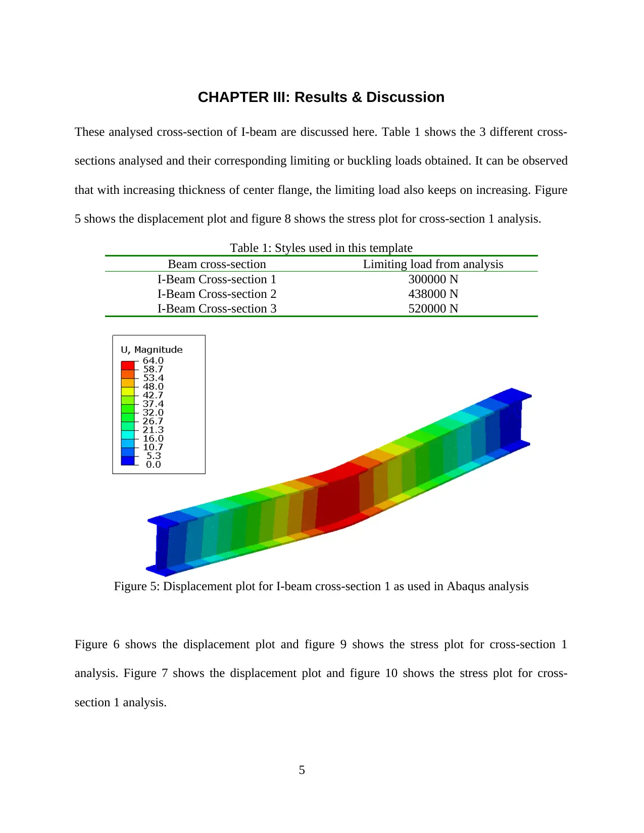
5 shows the displacement plot and figure 8 shows the stress plot for cross-section 1 analysis.
Table 1: Styles used in this template
Beam cross-section Limiting load from analysis
I-Beam Cross-section 1 300000 N
I-Beam Cross-section 2 438000 N
I-Beam Cross-section 3 520000 N
Figure 5: Displacement plot for I-beam cross-section 1 as used in Abaqus analysis
Figure 6 shows the displacement plot and figure 9 shows the stress plot for cross-section 1
analysis. Figure 7 shows the displacement plot and figure 10 shows the stress plot for cross-
section 1 analysis.
5
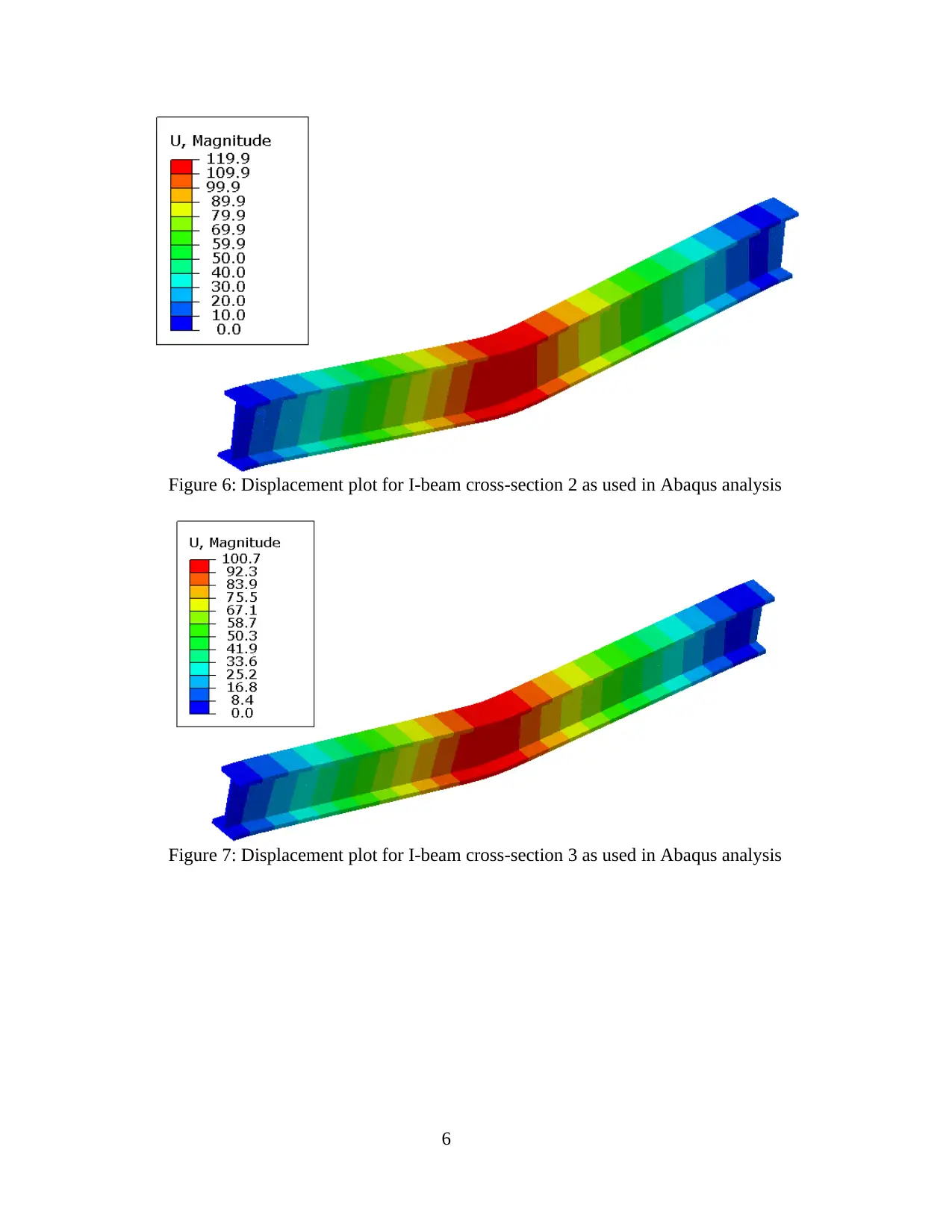
Figure 6: Displacement plot for I-beam cross-section 2 as used in Abaqus analysis
Figure 7: Displacement plot for I-beam cross-section 3 as used in Abaqus analysis
6
Figure 7: Displacement plot for I-beam cross-section 3 as used in Abaqus analysis
6
⊘ This is a preview!⊘
Do you want full access?
Subscribe today to unlock all pages.

Trusted by 1+ million students worldwide
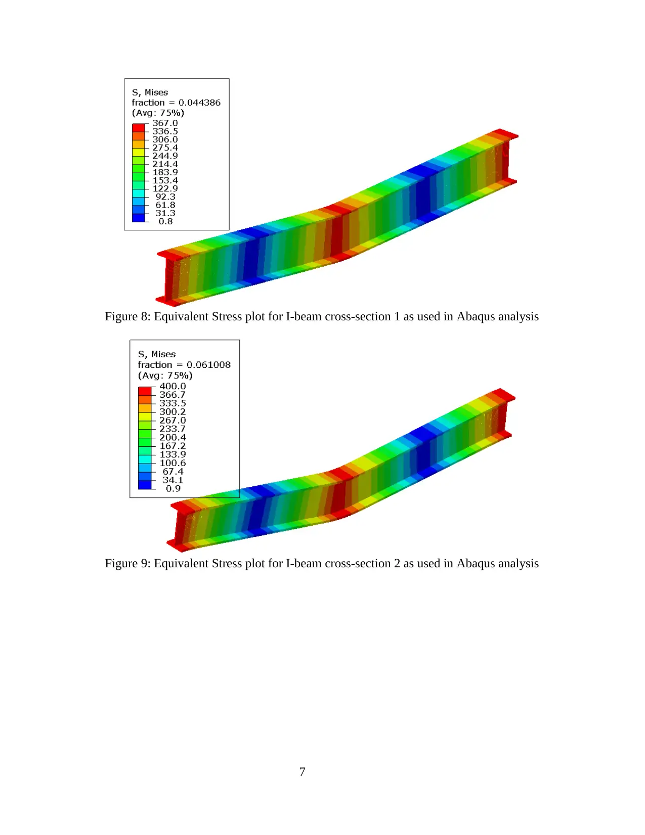
Figure 8: Equivalent Stress plot for I-beam cross-section 1 as used in Abaqus analysis
Figure 9: Equivalent Stress plot for I-beam cross-section 2 as used in Abaqus analysis
7
Figure 9: Equivalent Stress plot for I-beam cross-section 2 as used in Abaqus analysis
7
Paraphrase This Document
Need a fresh take? Get an instant paraphrase of this document with our AI Paraphraser
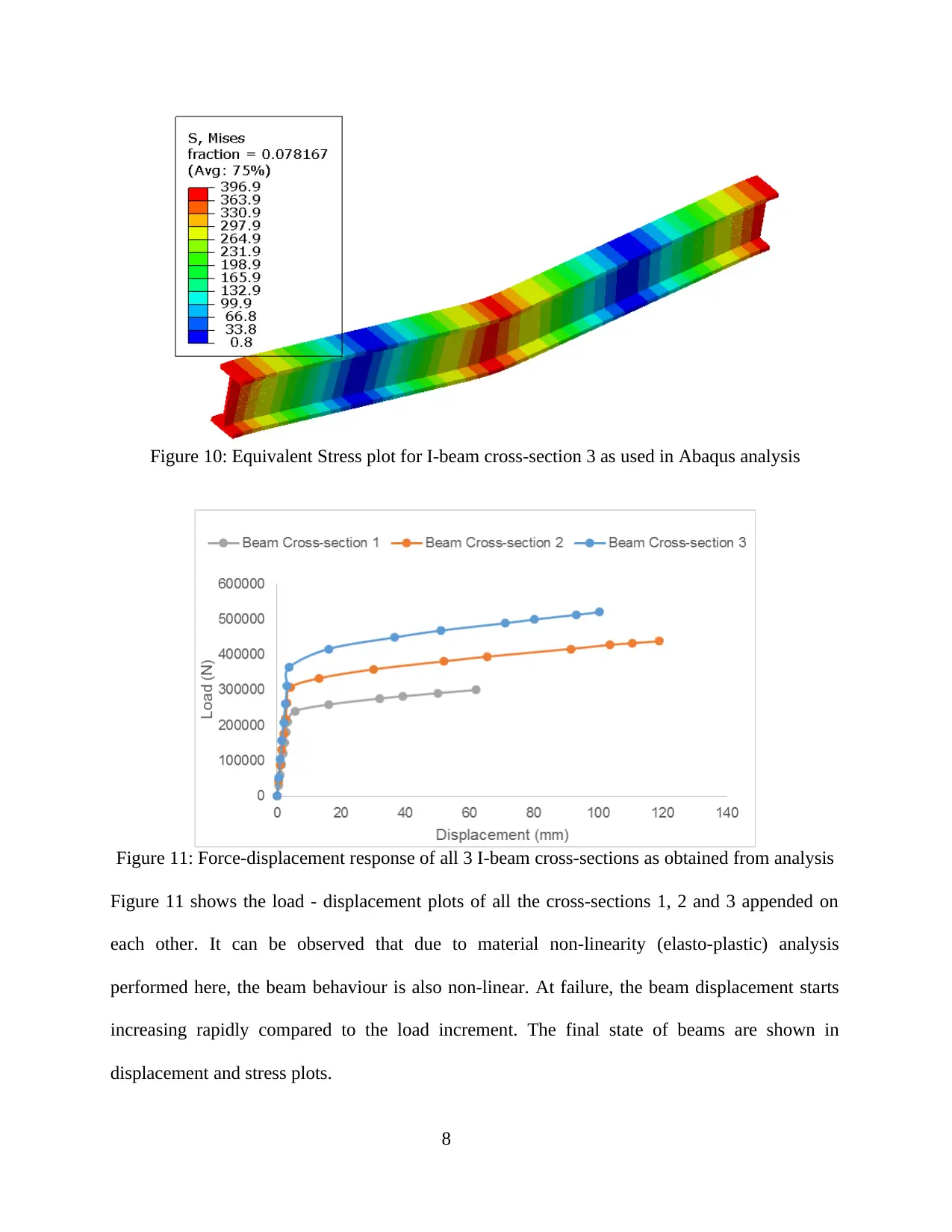
Figure 10: Equivalent Stress plot for I-beam cross-section 3 as used in Abaqus analysis
Figure 11: Force-displacement response of all 3 I-beam cross-sections as obtained from analysis
Figure 11 shows the load - displacement plots of all the cross-sections 1, 2 and 3 appended on
each other. It can be observed that due to material non-linearity (elasto-plastic) analysis
performed here, the beam behaviour is also non-linear. At failure, the beam displacement starts
increasing rapidly compared to the load increment. The final state of beams are shown in
displacement and stress plots.
8
CHAPTER IV: Conclusion
Three different I-beam cross-sections were chosen and analysed to compare for their buckling
strength under the application of a concentrated load. Finite element methods are used by means
of Abaqus modelling software. From the report, it was observed that the beam with highest
middle cross-sectional thickness yields the highest buckling load. The mesh, applied
concentrated load and boundary conditions are already discussed in previous section. As per
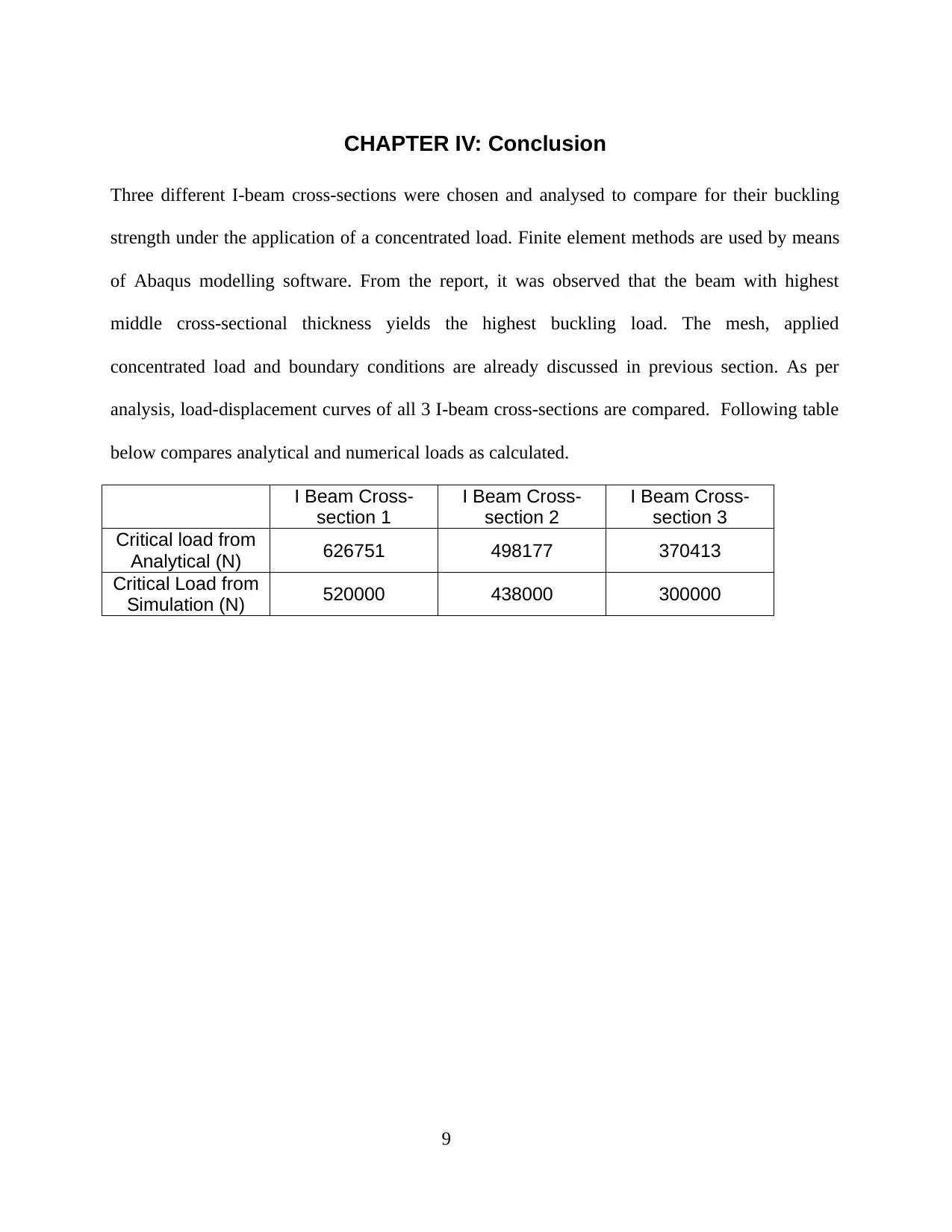
analysis, load-displacement curves of all 3 I-beam cross-sections are compared. Following table
below compares analytical and numerical loads as calculated.
I Beam Cross-
section 1
I Beam Cross-
section 2
I Beam Cross-
section 3
Critical load from
Analytical (N) 626751 498177 370413
Critical Load from
Simulation (N) 520000 438000 300000
9
⊘ This is a preview!⊘
Do you want full access?
Subscribe today to unlock all pages.

Trusted by 1+ million students worldwide
1 out of 12
Related Documents
Your All-in-One AI-Powered Toolkit for Academic Success.
+13062052269
info@desklib.com
Available 24*7 on WhatsApp / Email
![[object Object]](/_next/static/media/star-bottom.7253800d.svg)
Unlock your academic potential
Copyright © 2020–2025 A2Z Services. All Rights Reserved. Developed and managed by ZUCOL.


