Analysis of Leaf Spring: Safe Load Determination Using FEA
VerifiedAdded on 2023/06/04
|10
|5438
|314
Report
AI Summary
This report presents a static analysis of leaf springs, commonly used in automobile suspension systems, with a focus on determining safe stress and payload. The study highlights the advantage of leaf springs over helical springs, emphasizing their role in supporting vertical loads and isolating road-induced vibrations. A detailed analysis is performed on a leaf spring configuration from a TATA-407 light commercial vehicle using finite element analysis to determine safe stresses and payloads. The report includes a literature review, geometric properties of leaf springs, bending stress calculations, and length calculations. The analysis aims to identify the safe load, indicating a comfortable and safe driving speed, and references various research works in the field of leaf spring design and analysis.
STATIC ANALYSIS OF LEAF SPRING
G HARINATH GOWD1*
Associate Professor, Department of Mechanical Engineering
Sri Krishnadevaraya Engineering college,
NH-7, Gooty, Anantapur Dist, PIN 515 401
Andhra Pradesh., INDIA
hari.skd@gmail.com
E VENUGOPAL GOUD
Associate Professor, Department of Mechanical Engineering
Pullareddy Engineering college,
Kurnool, Anantapur Dist, PIN 515 401
Andhra Pradesh., INDIA
venugoud@gmail.com
1* Corresponding author, Email: hari.skd@gmail.com.
ABSTRACT
Leaf springs are special kind of springs used in automobile suspension systems. The advantage of leaf
spring over helical spring is that the ends of the spring may be guided along a definite path as it deflects to act as
a structural member in addition to energy absorbing device. The main function of leaf spring is not only to
support vertical load but also to isolate road induced vibrations. It is subjected to millions of load cycles leading
to fatigue failure. Static analysis determines the safe stress and corresponding pay load of the leaf spring and
also to study the behavior of structures under practical conditions. The present work attempts to analyze the safe
load of the leaf spring, which will indicate the speed at which a comfortable speed and safe drive is possible. A
typical leaf spring configuration of TATA-407 light commercial vehicle is chosen for study. Finite element
analysis has been carried out to determine the safe stresses and pay loads.
Keywords: Leaf spring, Geometric modeling, Static analysis.
1. INTRODUCTION
A spring is defined as an elastic body, whose function is to distort when loaded and to recover its
original shape when the load is removed. Leaf springs absorb the vehicle vibrations, shocks and bump loads
(induced due to road irregularities) by means of spring deflections, so that the potential energy is stored in the
leaf spring and then relieved slowly [1]. Ability to store and absorb more amount of strain energy ensures the
comfortable suspension system. Semi-elliptic leaf springs are almost universally used for suspension in light and
heavy commercial vehicles. For cars also, these are widely used in rear suspension. The spring consists of a
number of leaves called blades. The blades are varying in length. The blades are us usually given an initial
curvature or cambered so that they will tend to straighten under the load. The leaf spring is based upon the
theory of a beam of uniform strength. The lengthiest blade has eyes on its ends. This blade is called main or
master leaf, the remaining blades are called graduated leaves. All the blades are bound together by means of
steel straps.
The spring is mounted on the axle of the vehicle. The entire vehicle load rests on the leaf spring. The
front end of the spring is connected to the frame with a simple pin joint, while the rear end of the spring is
connected with a shackle. Shackle is the flexible link which connects between leaf spring rear eye and frame.
When the vehicle comes across a projection on the road surface, the wheel moves up, leading to deflection of
the spring. This changes the length between the spring eyes. If both the ends are fixed, the spring will not be
able to accommodate this change of length. So, to accommodate this change in length shackle is provided at one
end, which gives a flexible connection. The front eye of the leaf spring is constrained in all the directions, where
as rear eye is not constrained in X-direction. This rare eye is connected to the shackle. During loading the spring
deflects and moves in the direction perpendicular to the load applied.
When the leaf spring deflects, the upper side of each leaf tips slides or rubs against the lower side of the
leaf above it. This produces some damping which reduces spring vibrations, but since this available damping
may change with time, it is preferred not to avail of the same. Moreover, it produces squeaking sound. Further if
moisture is also present, such inter-leaf friction will cause fretting corrosion which decreases the fatigue
G Harinath Gowd et al. / International Journal of Engineering Science and Technology (IJEST)
ISSN : 0975-5462 Vol. 4 No.08 August 2012 3794
Paraphrase This Document
Need a fresh take? Get an instant paraphrase of this document with our AI Paraphraser
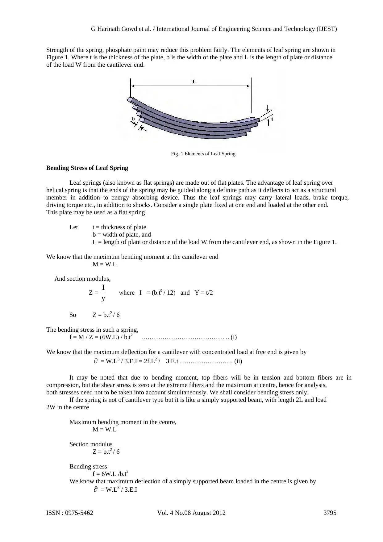
Strength of the spring, phosphate paint may reduce this problem fairly. The elements of leaf spring are shown in
Figure 1. Where t is the thickness of the plate, b is the width of the plate and L is the length of plate or distance
of the load W from the cantilever end.
Fig. 1 Elements of Leaf Spring
Bending Stress of Leaf Spring
Leaf springs (also known as flat springs) are made out of flat plates. The advantage of leaf spring over
helical spring is that the ends of the spring may be guided along a definite path as it deflects to act as a structural
member in addition to energy absorbing device. Thus the leaf springs may carry lateral loads, brake torque,
driving torque etc., in addition to shocks. Consider a single plate fixed at one end and loaded at the other end.
This plate may be used as a flat spring.
Let t = thickness of plate
b = width of plate, and
L = length of plate or distance of the load W from the cantilever end, as shown in the Figure 1.
We know that the maximum bending moment at the cantilever end
M = W.L
And section modulus,
Z = y
I where I = (b.t3 / 12) and Y = t/2
So Z = b.t2 / 6
The bending stress in such a spring,
f = M / Z = (6W.L) / b.t2 ………………………………… .. (i)
We know that the maximum deflection for a cantilever with concentrated load at free end is given by
= W.L3 / 3.E.I = 2f.L2 / 3.E.t ……………………. (ii)
It may be noted that due to bending moment, top fibers will be in tension and bottom fibers are in
compression, but the shear stress is zero at the extreme fibers and the maximum at centre, hence for analysis,
both stresses need not to be taken into account simultaneously. We shall consider bending stress only.
If the spring is not of cantilever type but it is like a simply supported beam, with length 2L and load
2W in the centre
Maximum bending moment in the centre,
M = W.L
Section modulus
Z = b.t2 / 6
Bending stress
f = 6W.L /b.t2
We know that maximum deflection of a simply supported beam loaded in the centre is given by
= W.L3 / 3.E.I
G Harinath Gowd et al. / International Journal of Engineering Science and Technology (IJEST)
ISSN : 0975-5462 Vol. 4 No.08 August 2012 3795
From above we see that a spring such as automobile spring (semi-elliptical spring) with length 2L and
load in the centre by a load 2W may be treated as double cantilever. If the plate of cantilever is cut into a series
of n strips of width b and these are placed as shown in Figure 1, then equations (i) and (ii) may be written as
f = 6W.L / n.b.t2 ………………………….. (iii)
= 4.W.L3 / n.E.b.t3 = 2.f.L2 /3.E.t …………… (iv)
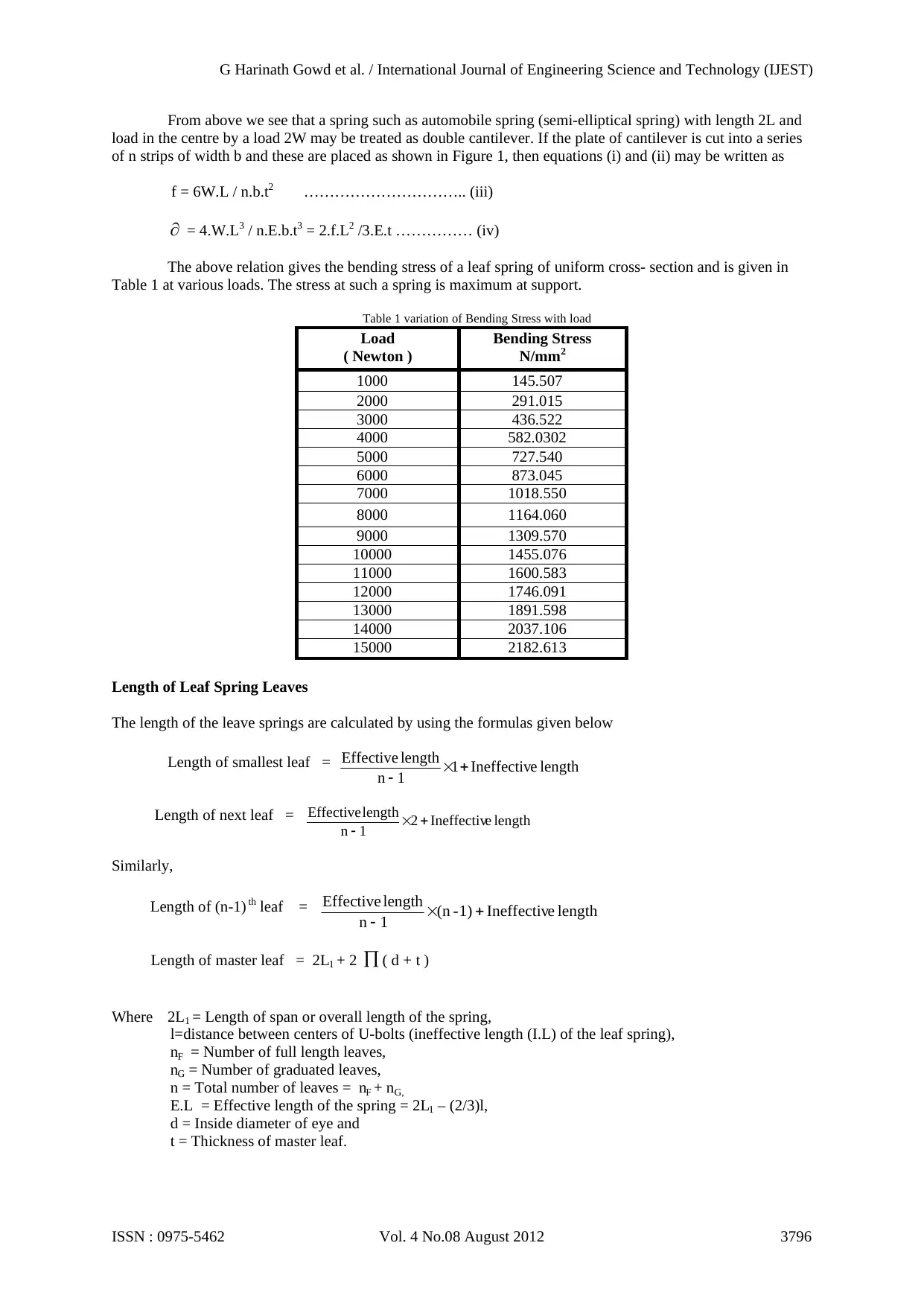
The above relation gives the bending stress of a leaf spring of uniform cross- section and is given in
Table 1 at various loads. The stress at such a spring is maximum at support.
Table 1 variation of Bending Stress with load
Load
( Newton )
Bending Stress
N/mm2
1000 145.507
2000 291.015
3000 436.522
4000 582.0302
5000 727.540
6000 873.045
7000 1018.550
8000 1164.060
9000 1309.570
10000 1455.076
11000 1600.583
12000 1746.091
13000 1891.598
14000 2037.106
15000 2182.613
Length of Leaf Spring Leaves
The length of the leave springs are calculated by using the formulas given below
Length of smallest leaf = lengtheIneffectiv1
1n
lengthEffective
Length of next leaf = lengtheIneffectiv2
1n
lengthEffective
Similarly,
Length of (n-1) th leaf = lengtheIneffectiv1)-(n
1n
lengthEffective
Length of master leaf = 2L1 + 2 ( d + t )
Where 2L1 = Length of span or overall length of the spring,
l=distance between centers of U-bolts (ineffective length (I.L) of the leaf spring),
nF = Number of full length leaves,
nG = Number of graduated leaves,
n = Total number of leaves = nF + nG,
E.L = Effective length of the spring = 2L1 – (2/3)l,
d = Inside diameter of eye and
t = Thickness of master leaf.
G Harinath Gowd et al. / International Journal of Engineering Science and Technology (IJEST)
ISSN : 0975-5462 Vol. 4 No.08 August 2012 3796
load in the centre by a load 2W may be treated as double cantilever. If the plate of cantilever is cut into a series
of n strips of width b and these are placed as shown in Figure 1, then equations (i) and (ii) may be written as
f = 6W.L / n.b.t2 ………………………….. (iii)
= 4.W.L3 / n.E.b.t3 = 2.f.L2 /3.E.t …………… (iv)
The above relation gives the bending stress of a leaf spring of uniform cross- section and is given in
Table 1 at various loads. The stress at such a spring is maximum at support.
Table 1 variation of Bending Stress with load
Load
( Newton )
Bending Stress
N/mm2
1000 145.507
2000 291.015
3000 436.522
4000 582.0302
5000 727.540
6000 873.045
7000 1018.550
8000 1164.060
9000 1309.570
10000 1455.076
11000 1600.583
12000 1746.091
13000 1891.598
14000 2037.106
15000 2182.613
Length of Leaf Spring Leaves
The length of the leave springs are calculated by using the formulas given below
Length of smallest leaf = lengtheIneffectiv1
1n
lengthEffective
Length of next leaf = lengtheIneffectiv2
1n
lengthEffective
Similarly,
Length of (n-1) th leaf = lengtheIneffectiv1)-(n
1n
lengthEffective
Length of master leaf = 2L1 + 2 ( d + t )
Where 2L1 = Length of span or overall length of the spring,
l=distance between centers of U-bolts (ineffective length (I.L) of the leaf spring),
nF = Number of full length leaves,
nG = Number of graduated leaves,
n = Total number of leaves = nF + nG,
E.L = Effective length of the spring = 2L1 – (2/3)l,
d = Inside diameter of eye and
t = Thickness of master leaf.
G Harinath Gowd et al. / International Journal of Engineering Science and Technology (IJEST)
ISSN : 0975-5462 Vol. 4 No.08 August 2012 3796
⊘ This is a preview!⊘
Do you want full access?
Subscribe today to unlock all pages.
Trusted by 1+ million students worldwide
Geometric Properties of leaf spring
Camber = 80 mm, Span = 1220 mm, Thickness = 7 mm, Width = 70 mm, Number of full length leaves n F = 2,
Number of graduated leaves nG = 8 and Total Number of leaves n = 10
2. LITERATURE SURVEY
Shiva Shankar and Vijayarangan [2] manufactured a composite mono leaf spring with an integral eye
and tested under static load conditions. Also fatigue life prediction was also done to ensure a reliable number of
life cycles of a leaf spring. Niklas philipson and Modelan modeled [3] a leaf spring in conventional way and
simulated for the kinematic and dynamic comparatives. Zhi’an Yang and et al. [4] studied the cyclic creep and
cyclic deformation. Efforts were taken for Finite Element Analysis of multi leaf springs. These springs were
simulated and analyzed by using ANSYS [5]. C.K. Clarke and G.E. Borowski [6] evaluated the failure of leaf
spring at different static load conditions and J.J. Fuentes et al. [7] studied the effect of premature fracture in
Automobile Leaf Springs. Mouleeswaran et al. [8] describes static and fatigue analysis of steel leaf springs and
composite multi leaf spring made up of glass fibre reinforced polymer using life data analysis. The dimensions
of existing conventional steel leaf springs of a light commercial vehicle are taken and are verified by design
calculations. Static analysis of 2-D model of conventional leaf spring is also performed using ANSYS 7.1and
compared with experimental results. H. A. Al-Qureshi [9] has described a single leaf, variable thickness spring
of glass fiber reinforced plastic (GFRP) with similar mechanical and geometrical properties to the multi leaf
steel spring, was designed, fabricated and tested. J.J.Fuentes et al. [10] in this work, the origin of premature
failure analysis procedures, including examining the leaf spring history, visual inspection of fractured
specimens, characterization of various properties and simulation tests on real components, were used. Rajendran
I, S. Vijayarangan [11] A formulation and solution technique using genetic algorithms (GA) for design
optimization of composite leaf springs is presented here. J.P. Hou et al. [12] explained the design evolution
process of a composite leaf spring for freight rail application. A.strzat and T.Paszek [13] performed a three
dimensional contact analysis of the car leaf spring. They considered static three dimensional contact problem of
the leaf car spring and the solution is obtained by finite element method performed in ADINA 7.5 professional
system. The maximum displacement of car spring is chosen as reliability criterion. Different types of
mathematical model were considered starting from the easiest beam model and ending on complicated three
dimensional non-linear model which takes into consideration large displacements and contact effects between
subsequent spring leaves. The static characteristics of the car spring was obtained for different models and later
on, it is compared with one obtained from experimental investigations. Fu-Cheng Wang [14] performed a
detailed study on leaf springs. Classical network theory is applied to analyze the behavior of a leaf spring in an
active suspension system. I.Rajendran and S.Vijayarangan [15] performed a finite element analysis on a typical
leaf spring of a passenger car. Finite element analysis has been carried out to determine natural frequencies and
mode shapes of the leaf spring by considering a simple road surface model. Further more literatures are
available on concepts and design of leaf springs [16-17]. The dimensions and the properties of the materials are
taken from the spring manufacturing companies catalogues [18 - 19].
The present work attempts to find the maximum pay load of the vehicle by performing static analysis
using ANSYS software and the obtained results are compared with the mathematical calculations and the
maximum bending stress and the corresponding pay load is determined by considering the factor of safety.
3. MODELING & ANALYSIS OF LEAF SPRING
In computer-aided design, geometric modeling is concerned with the computer compatible
mathematical description of the geometry of an object. The mathematical description allows the model of the
object to be displayed and manipulated on a graphics terminal through signals from the CPU of the CAD
system. The software that provides geometric modeling capabilities must be designed for efficient use both by
the computer and the human designer.
To use geometric modeling, the designer constructs the graphical model of the object on the CRT
screen of the ICG system by inputting three types of commands to the computer. The first type of command
generates basic geometric elements such as points, lines, and circles. The second type command is used to
accomplish scaling, rotation, or other transformations of these elements. The third type of command causes the
various elements to be joined into the desired shape of the object being created on the ICG system. During this
geometric process, the computer converts the commands into a mathematical model, stores it in the computer
data files, and displays it as an image on the CRT screen. The model can subsequently be called from the data
files for review, analysis, or alteration. The most advanced method of geometric modeling is solid modeling in
three dimensions.
G Harinath Gowd et al. / International Journal of Engineering Science and Technology (IJEST)
ISSN : 0975-5462 Vol. 4 No.08 August 2012 3797
Paraphrase This Document
Need a fresh take? Get an instant paraphrase of this document with our AI Paraphraser
Modeling Procedure for Leaf Spring
1. First create the key point 100 at origin, i.e. x ,y, z = (0, 0, 0).
2. Create another key point 200 at some arbitrary distance in Z-direction, say x, y, z = (0, 0, 200).
3. Join the above two key points 100 and 200 to get the reference axis.
4. By using data from mathematical analysis Create the key point1 with a distance of radius of curvature R1
in vertically down-ward direction, i.e. x, y, z = (0, -R1, 0).
5. Similarly key points 2 and 3 correspond to R2, i.e. x, y, z = (0, -R2, 0) and key points 4 and 5 corresponds
to R3, i.e. x, y, z = (0, -R3, 0).
6. Key point 20 corresponds to R11. i.e. x, y, z = (0, -R11, 0).
7. Join the pair of key points sequentially as follows Key points 1 and 2, 2 and 3, 3 and 4...and 19 and 20.
8. Then line1 formed by the key points 1 and 2, line2 formed by the key points 2 and 3 and line10 formed by
the key points 19 and 20.
9. Extrude the above lines with respect to reference axis stated in step3 as follows:
Extrude line1 with an angle Ф1, will get area1
Extrude line2 with an angle Ф2, will get area2,………and
Extrude line10 with an angle Ф10, will get area10.
10. After extruding all the lines, the semi area of the spring without eye will form on XY- plane with
significant degeneracy.
11. To avoid degeneracy, extend the right side line of smallest area i.e. area 10 to some extent such that it
cross the top most area i.e. area1.Now divide area by line. For this, select the areas left to extended line1
and divide with that line. Similarly, extend the right side line of second smallest area i.e. area9 to some
extent such that it cross the top most area i.e. area1. Again divide area by line.
For this select the areas left to extended line2 and divide with that line.
12. The above process is to be done up to extension of line of area9 and divide area area by extension line9.
13. Now perfect half area of leaf spring without eye will form.
14. Eye construction:
Extend the right side line of top most area i.e. area1 to the length equal to the radius of eye. Delete lines
only, so that key point of that line will remain. Shift the origin to that key point. Create another key point
say some key point300 in Z-direction. Join the above two key points to get reference axis to rotate the right
side line of area1. Extrude the line with respect to reference axis to an angle 2750 to 2800. Delete all
reference lines. So half area of leaf spring with eye is formed.
15. To get the full area of the leaf spring. Shift the origin to the top left most area key point i.e. key point1.
Reflect the entire area with respect to YZ – plane.
16. To get the solid model of the leaf spring, extrude the area by Z-offset to a length equal to the width of the
leaf spring.
17. To make a cylindrical hole at centre of the leaf spring to provide bolting for all the leaves, so that all the
leaves are in perfect alignment: Create centre key point of the leaf spring on the top view i.e. XY-plane,
by using key points between key points’ command. Shift the origin to that key point. Choose the proper
work plane by using work plane Create a cylinder along Z-axis in vertically downward direction.
Subtract the cylinder from the solid leaf spring. So that leaf spring with hole to provide bolt will obtain.
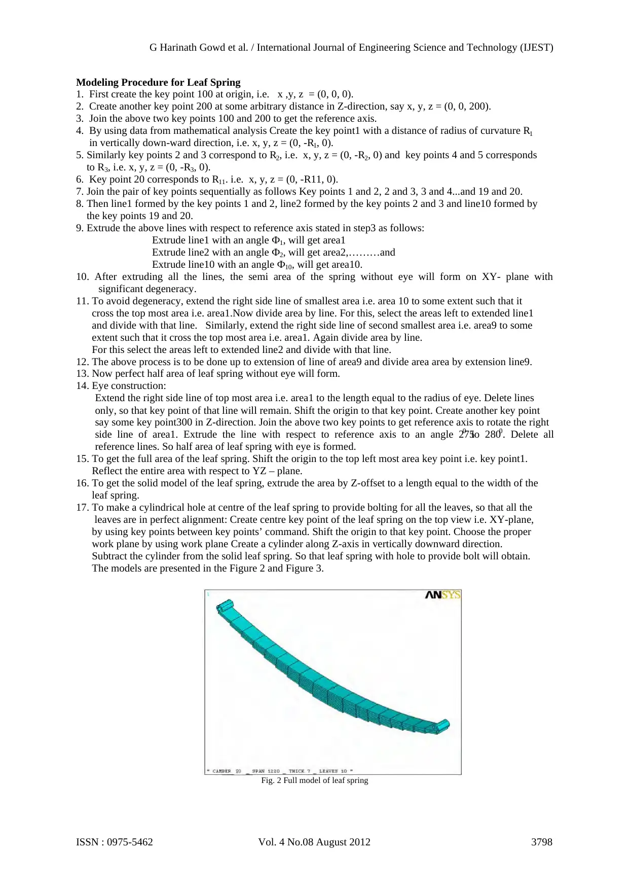
The models are presented in the Figure 2 and Figure 3.
Fig. 2 Full model of leaf spring
G Harinath Gowd et al. / International Journal of Engineering Science and Technology (IJEST)
ISSN : 0975-5462 Vol. 4 No.08 August 2012 3798
1. First create the key point 100 at origin, i.e. x ,y, z = (0, 0, 0).
2. Create another key point 200 at some arbitrary distance in Z-direction, say x, y, z = (0, 0, 200).
3. Join the above two key points 100 and 200 to get the reference axis.
4. By using data from mathematical analysis Create the key point1 with a distance of radius of curvature R1
in vertically down-ward direction, i.e. x, y, z = (0, -R1, 0).
5. Similarly key points 2 and 3 correspond to R2, i.e. x, y, z = (0, -R2, 0) and key points 4 and 5 corresponds
to R3, i.e. x, y, z = (0, -R3, 0).
6. Key point 20 corresponds to R11. i.e. x, y, z = (0, -R11, 0).
7. Join the pair of key points sequentially as follows Key points 1 and 2, 2 and 3, 3 and 4...and 19 and 20.
8. Then line1 formed by the key points 1 and 2, line2 formed by the key points 2 and 3 and line10 formed by
the key points 19 and 20.
9. Extrude the above lines with respect to reference axis stated in step3 as follows:
Extrude line1 with an angle Ф1, will get area1
Extrude line2 with an angle Ф2, will get area2,………and
Extrude line10 with an angle Ф10, will get area10.
10. After extruding all the lines, the semi area of the spring without eye will form on XY- plane with
significant degeneracy.
11. To avoid degeneracy, extend the right side line of smallest area i.e. area 10 to some extent such that it
cross the top most area i.e. area1.Now divide area by line. For this, select the areas left to extended line1
and divide with that line. Similarly, extend the right side line of second smallest area i.e. area9 to some
extent such that it cross the top most area i.e. area1. Again divide area by line.
For this select the areas left to extended line2 and divide with that line.
12. The above process is to be done up to extension of line of area9 and divide area area by extension line9.
13. Now perfect half area of leaf spring without eye will form.
14. Eye construction:
Extend the right side line of top most area i.e. area1 to the length equal to the radius of eye. Delete lines
only, so that key point of that line will remain. Shift the origin to that key point. Create another key point
say some key point300 in Z-direction. Join the above two key points to get reference axis to rotate the right
side line of area1. Extrude the line with respect to reference axis to an angle 2750 to 2800. Delete all
reference lines. So half area of leaf spring with eye is formed.
15. To get the full area of the leaf spring. Shift the origin to the top left most area key point i.e. key point1.
Reflect the entire area with respect to YZ – plane.
16. To get the solid model of the leaf spring, extrude the area by Z-offset to a length equal to the width of the
leaf spring.
17. To make a cylindrical hole at centre of the leaf spring to provide bolting for all the leaves, so that all the
leaves are in perfect alignment: Create centre key point of the leaf spring on the top view i.e. XY-plane,
by using key points between key points’ command. Shift the origin to that key point. Choose the proper
work plane by using work plane Create a cylinder along Z-axis in vertically downward direction.
Subtract the cylinder from the solid leaf spring. So that leaf spring with hole to provide bolt will obtain.
The models are presented in the Figure 2 and Figure 3.
Fig. 2 Full model of leaf spring
G Harinath Gowd et al. / International Journal of Engineering Science and Technology (IJEST)
ISSN : 0975-5462 Vol. 4 No.08 August 2012 3798
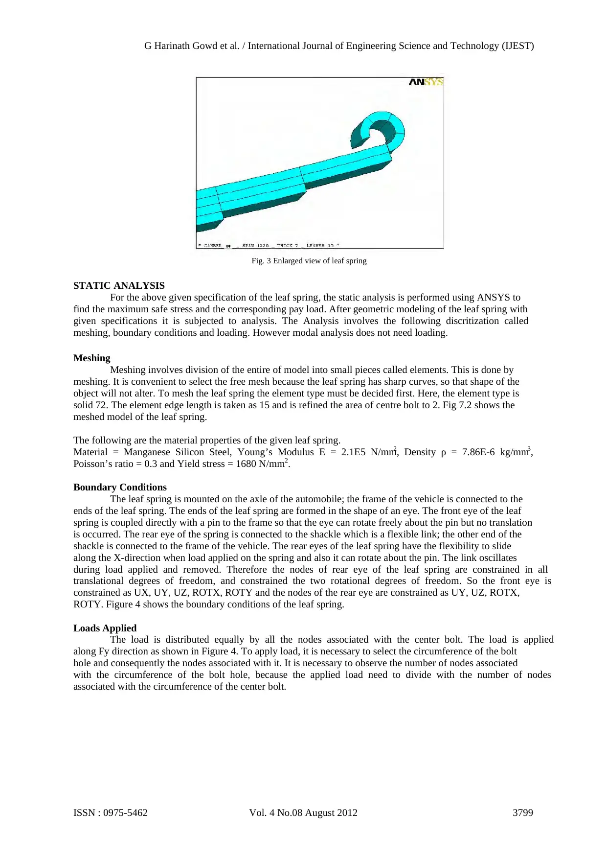
Fig. 3 Enlarged view of leaf spring
STATIC ANALYSIS
For the above given specification of the leaf spring, the static analysis is performed using ANSYS to
find the maximum safe stress and the corresponding pay load. After geometric modeling of the leaf spring with
given specifications it is subjected to analysis. The Analysis involves the following discritization called
meshing, boundary conditions and loading. However modal analysis does not need loading.
Meshing
Meshing involves division of the entire of model into small pieces called elements. This is done by
meshing. It is convenient to select the free mesh because the leaf spring has sharp curves, so that shape of the
object will not alter. To mesh the leaf spring the element type must be decided first. Here, the element type is
solid 72. The element edge length is taken as 15 and is refined the area of centre bolt to 2. Fig 7.2 shows the
meshed model of the leaf spring.
The following are the material properties of the given leaf spring.
Material = Manganese Silicon Steel, Young’s Modulus E = 2.1E5 N/mm2, Density ρ = 7.86E-6 kg/mm3,
Poisson’s ratio = 0.3 and Yield stress = 1680 N/mm2.
Boundary Conditions
The leaf spring is mounted on the axle of the automobile; the frame of the vehicle is connected to the
ends of the leaf spring. The ends of the leaf spring are formed in the shape of an eye. The front eye of the leaf
spring is coupled directly with a pin to the frame so that the eye can rotate freely about the pin but no translation
is occurred. The rear eye of the spring is connected to the shackle which is a flexible link; the other end of the
shackle is connected to the frame of the vehicle. The rear eyes of the leaf spring have the flexibility to slide
along the X-direction when load applied on the spring and also it can rotate about the pin. The link oscillates
during load applied and removed. Therefore the nodes of rear eye of the leaf spring are constrained in all
translational degrees of freedom, and constrained the two rotational degrees of freedom. So the front eye is
constrained as UX, UY, UZ, ROTX, ROTY and the nodes of the rear eye are constrained as UY, UZ, ROTX,
ROTY. Figure 4 shows the boundary conditions of the leaf spring.
Loads Applied
The load is distributed equally by all the nodes associated with the center bolt. The load is applied
along Fy direction as shown in Figure 4. To apply load, it is necessary to select the circumference of the bolt
hole and consequently the nodes associated with it. It is necessary to observe the number of nodes associated
with the circumference of the bolt hole, because the applied load need to divide with the number of nodes
associated with the circumference of the center bolt.
G Harinath Gowd et al. / International Journal of Engineering Science and Technology (IJEST)
ISSN : 0975-5462 Vol. 4 No.08 August 2012 3799
⊘ This is a preview!⊘
Do you want full access?
Subscribe today to unlock all pages.
Trusted by 1+ million students worldwide
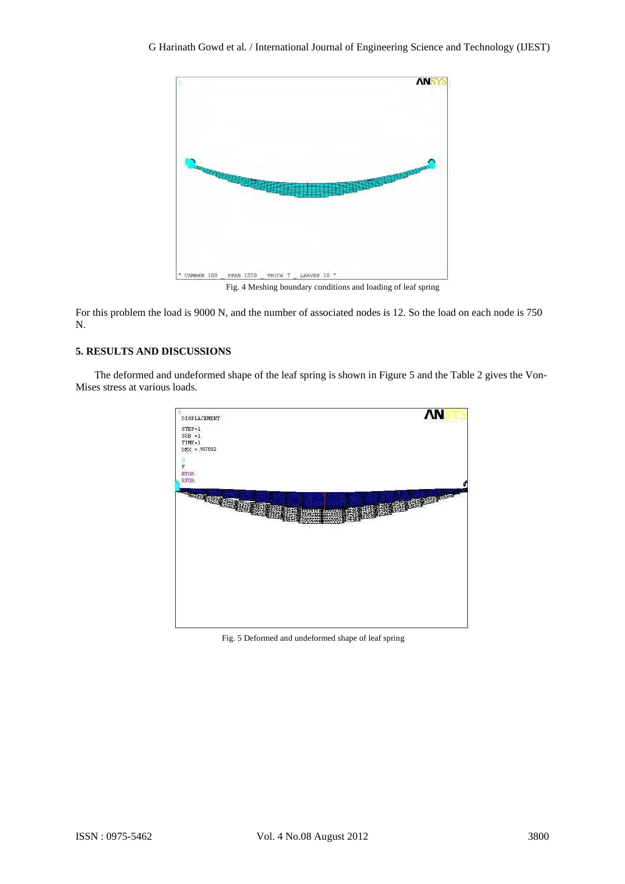
Fig. 4 Meshing boundary conditions and loading of leaf spring
For this problem the load is 9000 N, and the number of associated nodes is 12. So the load on each node is 750
N.
5. RESULTS AND DISCUSSIONS
The deformed and undeformed shape of the leaf spring is shown in Figure 5 and the Table 2 gives the Von-
Mises stress at various loads.
Fig. 5 Deformed and undeformed shape of leaf spring
G Harinath Gowd et al. / International Journal of Engineering Science and Technology (IJEST)
ISSN : 0975-5462 Vol. 4 No.08 August 2012 3800
Paraphrase This Document
Need a fresh take? Get an instant paraphrase of this document with our AI Paraphraser
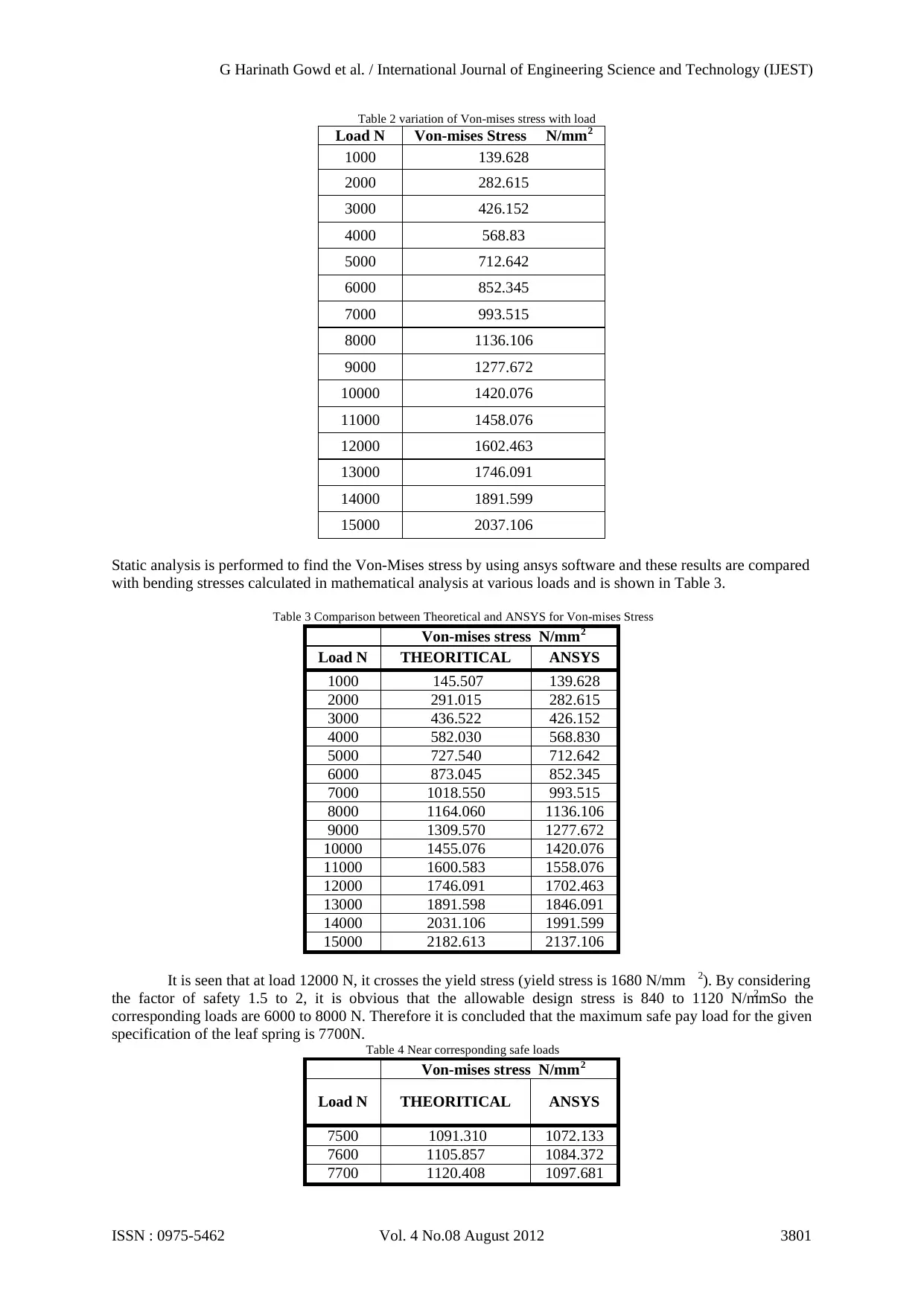
Table 2 variation of Von-mises stress with load
Load N Von-mises Stress N/mm2
1000 139.628
2000 282.615
3000 426.152
4000 568.83
5000 712.642
6000 852.345
7000 993.515
8000 1136.106
9000 1277.672
10000 1420.076
11000 1458.076
12000 1602.463
13000 1746.091
14000 1891.599
15000 2037.106
Static analysis is performed to find the Von-Mises stress by using ansys software and these results are compared
with bending stresses calculated in mathematical analysis at various loads and is shown in Table 3.
Table 3 Comparison between Theoretical and ANSYS for Von-mises Stress
Von-mises stress N/mm2
Load N THEORITICAL ANSYS
1000 145.507 139.628
2000 291.015 282.615
3000 436.522 426.152
4000 582.030 568.830
5000 727.540 712.642
6000 873.045 852.345
7000 1018.550 993.515
8000 1164.060 1136.106
9000 1309.570 1277.672
10000 1455.076 1420.076
11000 1600.583 1558.076
12000 1746.091 1702.463
13000 1891.598 1846.091
14000 2031.106 1991.599
15000 2182.613 2137.106
It is seen that at load 12000 N, it crosses the yield stress (yield stress is 1680 N/mm 2). By considering
the factor of safety 1.5 to 2, it is obvious that the allowable design stress is 840 to 1120 N/mm2. So the
corresponding loads are 6000 to 8000 N. Therefore it is concluded that the maximum safe pay load for the given
specification of the leaf spring is 7700N. Table 4 Near corresponding safe loads
Von-mises stress N/mm2
Load N THEORITICAL ANSYS
7500 1091.310 1072.133
7600 1105.857 1084.372
7700 1120.408 1097.681
G Harinath Gowd et al. / International Journal of Engineering Science and Technology (IJEST)
ISSN : 0975-5462 Vol. 4 No.08 August 2012 3801
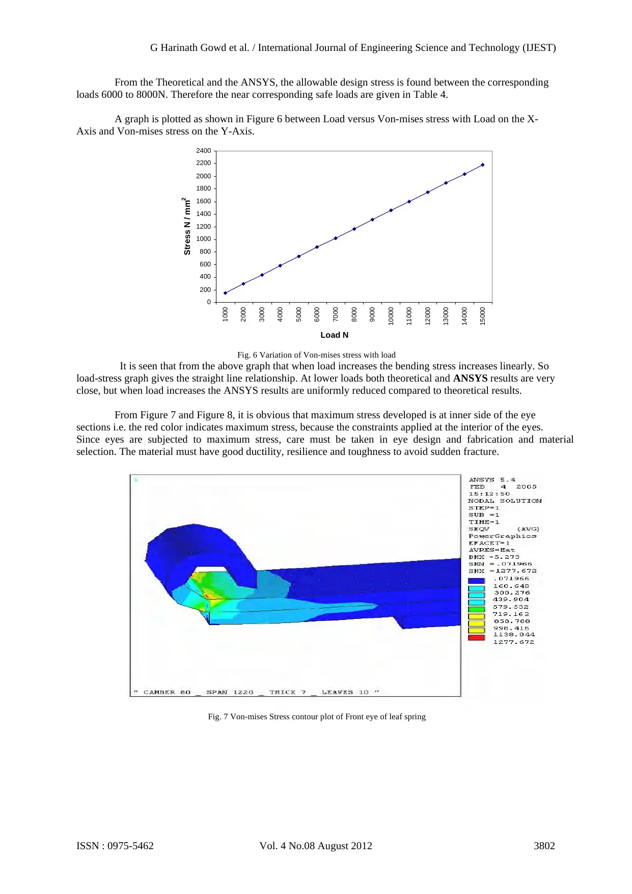
From the Theoretical and the ANSYS, the allowable design stress is found between the corresponding
loads 6000 to 8000N. Therefore the near corresponding safe loads are given in Table 4.
A graph is plotted as shown in Figure 6 between Load versus Von-mises stress with Load on the X-
Axis and Von-mises stress on the Y-Axis.
0
200
400
600
800
1000
1200
1400
1600
1800
2000
2200
2400
1000
2000
3000
4000
5000
6000
7000
8000
9000
10000
11000
12000
13000
14000
15000
Load N
Stress N / mm2
Fig. 6 Variation of Von-mises stress with load
It is seen that from the above graph that when load increases the bending stress increases linearly. So
load-stress graph gives the straight line relationship. At lower loads both theoretical and ANSYS results are very
close, but when load increases the ANSYS results are uniformly reduced compared to theoretical results.
From Figure 7 and Figure 8, it is obvious that maximum stress developed is at inner side of the eye
sections i.e. the red color indicates maximum stress, because the constraints applied at the interior of the eyes.
Since eyes are subjected to maximum stress, care must be taken in eye design and fabrication and material
selection. The material must have good ductility, resilience and toughness to avoid sudden fracture.
Fig. 7 Von-mises Stress contour plot of Front eye of leaf spring
G Harinath Gowd et al. / International Journal of Engineering Science and Technology (IJEST)
ISSN : 0975-5462 Vol. 4 No.08 August 2012 3802
⊘ This is a preview!⊘
Do you want full access?
Subscribe today to unlock all pages.
Trusted by 1+ million students worldwide
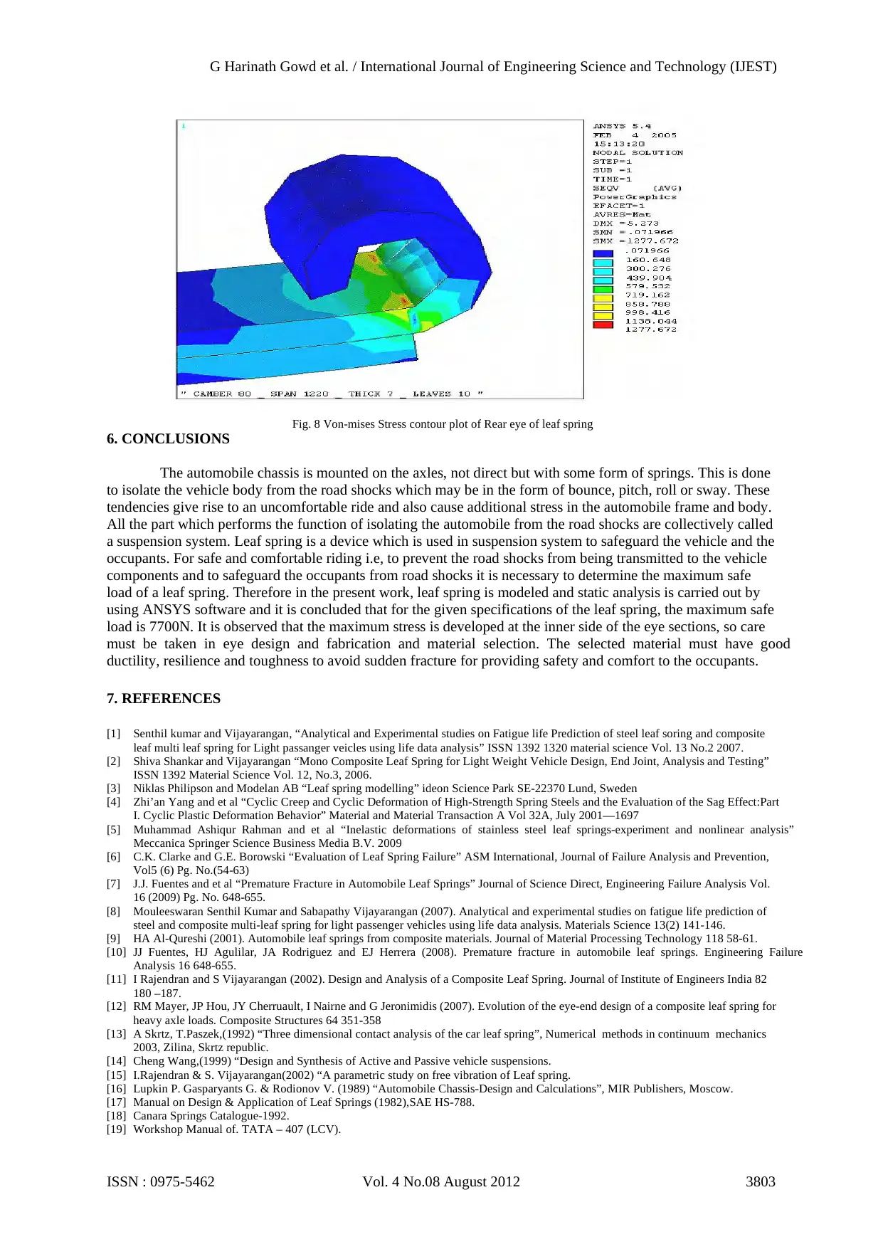
Fig. 8 Von-mises Stress contour plot of Rear eye of leaf spring
6. CONCLUSIONS
The automobile chassis is mounted on the axles, not direct but with some form of springs. This is done
to isolate the vehicle body from the road shocks which may be in the form of bounce, pitch, roll or sway. These
tendencies give rise to an uncomfortable ride and also cause additional stress in the automobile frame and body.
All the part which performs the function of isolating the automobile from the road shocks are collectively called
a suspension system. Leaf spring is a device which is used in suspension system to safeguard the vehicle and the
occupants. For safe and comfortable riding i.e, to prevent the road shocks from being transmitted to the vehicle
components and to safeguard the occupants from road shocks it is necessary to determine the maximum safe
load of a leaf spring. Therefore in the present work, leaf spring is modeled and static analysis is carried out by
using ANSYS software and it is concluded that for the given specifications of the leaf spring, the maximum safe
load is 7700N. It is observed that the maximum stress is developed at the inner side of the eye sections, so care
must be taken in eye design and fabrication and material selection. The selected material must have good
ductility, resilience and toughness to avoid sudden fracture for providing safety and comfort to the occupants.
7. REFERENCES
[1] Senthil kumar and Vijayarangan, “Analytical and Experimental studies on Fatigue life Prediction of steel leaf soring and composite
leaf multi leaf spring for Light passanger veicles using life data analysis” ISSN 1392 1320 material science Vol. 13 No.2 2007.
[2] Shiva Shankar and Vijayarangan “Mono Composite Leaf Spring for Light Weight Vehicle Design, End Joint, Analysis and Testing”
ISSN 1392 Material Science Vol. 12, No.3, 2006.
[3] Niklas Philipson and Modelan AB “Leaf spring modelling” ideon Science Park SE-22370 Lund, Sweden
[4] Zhi’an Yang and et al “Cyclic Creep and Cyclic Deformation of High-Strength Spring Steels and the Evaluation of the Sag Effect:Part
I. Cyclic Plastic Deformation Behavior” Material and Material Transaction A Vol 32A, July 2001—1697
[5] Muhammad Ashiqur Rahman and et al “Inelastic deformations of stainless steel leaf springs-experiment and nonlinear analysis”
Meccanica Springer Science Business Media B.V. 2009
[6] C.K. Clarke and G.E. Borowski “Evaluation of Leaf Spring Failure” ASM International, Journal of Failure Analysis and Prevention,
Vol5 (6) Pg. No.(54-63)
[7] J.J. Fuentes and et al “Premature Fracture in Automobile Leaf Springs” Journal of Science Direct, Engineering Failure Analysis Vol.
16 (2009) Pg. No. 648-655.
[8] Mouleeswaran Senthil Kumar and Sabapathy Vijayarangan (2007). Analytical and experimental studies on fatigue life prediction of
steel and composite multi-leaf spring for light passenger vehicles using life data analysis. Materials Science 13(2) 141-146.
[9] HA Al-Qureshi (2001). Automobile leaf springs from composite materials. Journal of Material Processing Technology 118 58-61.
[10] JJ Fuentes, HJ Agulilar, JA Rodriguez and EJ Herrera (2008). Premature fracture in automobile leaf springs. Engineering Failure
Analysis 16 648-655.
[11] I Rajendran and S Vijayarangan (2002). Design and Analysis of a Composite Leaf Spring. Journal of Institute of Engineers India 82
180 –187.
[12] RM Mayer, JP Hou, JY Cherruault, I Nairne and G Jeronimidis (2007). Evolution of the eye-end design of a composite leaf spring for
heavy axle loads. Composite Structures 64 351-358
[13] A Skrtz, T.Paszek,(1992) “Three dimensional contact analysis of the car leaf spring”, Numerical methods in continuum mechanics
2003, Zilina, Skrtz republic.
[14] Cheng Wang,(1999) “Design and Synthesis of Active and Passive vehicle suspensions.
[15] I.Rajendran & S. Vijayarangan(2002) “A parametric study on free vibration of Leaf spring.
[16] Lupkin P. Gasparyants G. & Rodionov V. (1989) “Automobile Chassis-Design and Calculations”, MIR Publishers, Moscow.
[17] Manual on Design & Application of Leaf Springs (1982),SAE HS-788.
[18] Canara Springs Catalogue-1992.
[19] Workshop Manual of. TATA – 407 (LCV).
G Harinath Gowd et al. / International Journal of Engineering Science and Technology (IJEST)
ISSN : 0975-5462 Vol. 4 No.08 August 2012 3803
1 out of 10


Your All-in-One AI-Powered Toolkit for Academic Success.
+13062052269
info@desklib.com
Available 24*7 on WhatsApp / Email
![[object Object]](/_next/static/media/star-bottom.7253800d.svg)
Unlock your academic potential
Copyright © 2020–2026 A2Z Services. All Rights Reserved. Developed and managed by ZUCOL.