ELEE1144 Project: Arduino Controlled Line Following Wheeled Robot
VerifiedAdded on 2023/06/15
|22
|2697
|462
Project
AI Summary
This document presents a detailed solution for a line following robot project using an Arduino Pro Mini. The robot's design is divided into control, sensor, and driver sections. The sensor section uses IR diodes and comparators to detect the line, while the control section uses the Arduino to process the sensor data and send commands to the motor driver. The driver section, which includes DC motors and a motor driver, powers the robot's movement. The report explains the circuit diagram, program logic, and the robot's operational principles, including how it responds to different sensor inputs to follow a line accurately. The use of Arduino Pro Mini is emphasized due to its ease of programming and incorporation on a breadboard. This project showcases the integration of hardware and software components to achieve autonomous line following capabilities.
Robot 1
LINE FOLLOWER
Month day, Year
Words
Student’s Name
Institution
LINE FOLLOWER
Month day, Year
Words
Student’s Name
Institution
Paraphrase This Document
Need a fresh take? Get an instant paraphrase of this document with our AI Paraphraser
Robot 2
Abstract
The robot’s design can be split into three sections; control section, sensor section and driver
section. The arduino being used is the Arduino pro mini that has the accessible and simple user
experience. It has been used in numerous project applications. An added advantage is the easy-
to-use arduino software that is quite flexible for advance and beginner applications. Other
components used and connected as in the circuit diagram allowed the robot follow the line with
detection from the IR modules. Caution had to be taken in making a program that made use of
the logic truth table for proper operation and robot movement.
Keywords: Arduino, logic, comparator
Robot 3
Introduction
The designed robot is made to follow a line. The line could be white or black in Colour. These
types of robots are mainly categorized into two, robots that follow the black line and the other
type is robots that follow a white line. The major decision made by the robot is sensing the line
to follow and running over it1.
Concept
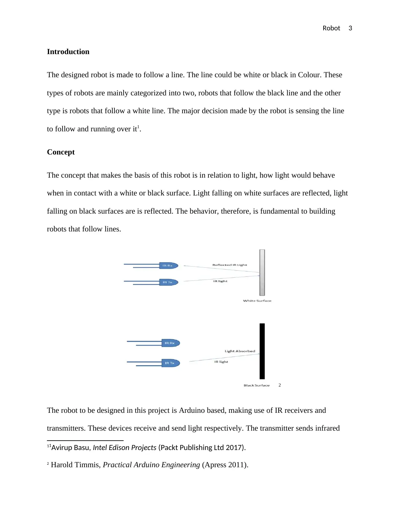
The concept that makes the basis of this robot is in relation to light, how light would behave
when in contact with a white or black surface. Light falling on white surfaces are reflected, light
falling on black surfaces are is reflected. The behavior, therefore, is fundamental to building
robots that follow lines.
2
The robot to be designed in this project is Arduino based, making use of IR receivers and
transmitters. These devices receive and send light respectively. The transmitter sends infrared
11Avirup Basu, Intel Edison Projects (Packt Publishing Ltd 2017).
2 Harold Timmis, Practical Arduino Engineering (Apress 2011).
Introduction
The designed robot is made to follow a line. The line could be white or black in Colour. These
types of robots are mainly categorized into two, robots that follow the black line and the other
type is robots that follow a white line. The major decision made by the robot is sensing the line
to follow and running over it1.
Concept
The concept that makes the basis of this robot is in relation to light, how light would behave
when in contact with a white or black surface. Light falling on white surfaces are reflected, light
falling on black surfaces are is reflected. The behavior, therefore, is fundamental to building
robots that follow lines.
2
The robot to be designed in this project is Arduino based, making use of IR receivers and
transmitters. These devices receive and send light respectively. The transmitter sends infrared
11Avirup Basu, Intel Edison Projects (Packt Publishing Ltd 2017).
2 Harold Timmis, Practical Arduino Engineering (Apress 2011).
⊘ This is a preview!⊘
Do you want full access?
Subscribe today to unlock all pages.
Trusted by 1+ million students worldwide
Robot 4
light which would fall on the surface, either on a white or black surface. If the rays fall on a
white surface greater percentage of it would be reflected back and received by the receiver that
would generate changes in voltage. When the rays fall on black surfaces, the greater percentage
would be absorbed with the very little amount being received by the receiver thereby no
significant voltage changes would be generated.
This robot is Arduino based in that the sensing of a white surface leading so voltage changes
produce an input to the Arduino but black surfaces would not produce such an input3.
Components Required
1. Arduino
The arduino chosen was arduino pro mini whose advantage is the easy-to-use Arduino
software that is quite flexible for advance and beginner applications. The software has the
capability of running in Windows, Mac and Linux, key in robot programming. Other
microcontrollers that may have been used include Phidgets, Parallax Basic Stamp,
Handyboard and BX24. Most architects and designers have built interactive prototypes that
are applied in music and art in the installation and experimentation f new instruments of
music. Such features have made it possible for hobbyists, children, programmers and artists
come up with inventions simply from following instructions available online. These other
microcontrollers also exhibit the same advantages as the used Arduino microcontroller. The
reasons for picking Arduino pro mini microcontroller include4
3 John-David Warren, Josh Adams and Harald Molle, Arduino Robotics (illustrated edn, Apress
2011).
4 Harold Timmis, Practical Arduino Engineering (illustrated edn, Apress 2011).
Paraphrase This Document
Need a fresh take? Get an instant paraphrase of this document with our AI Paraphraser
Robot 5
Cross-platform
The software is able to run on Mac, Linux and Windows operating systems.
Inexpensive
Its board is less expensive if compared to the other named microcontrollers.
Clear, simple programming language
The IDE of Arduino software can be used by beginners for simple application as well
as advance purposes. Similarly, the software can be used in teaching conveniently in
the programming environment thereby making familiarization easier.
Extensible Hardware.
Other than experienced individuals in making Arduino circuits using it, the Arduino
connection is that simple to allow relatively experienced individuals build properly
functioning.
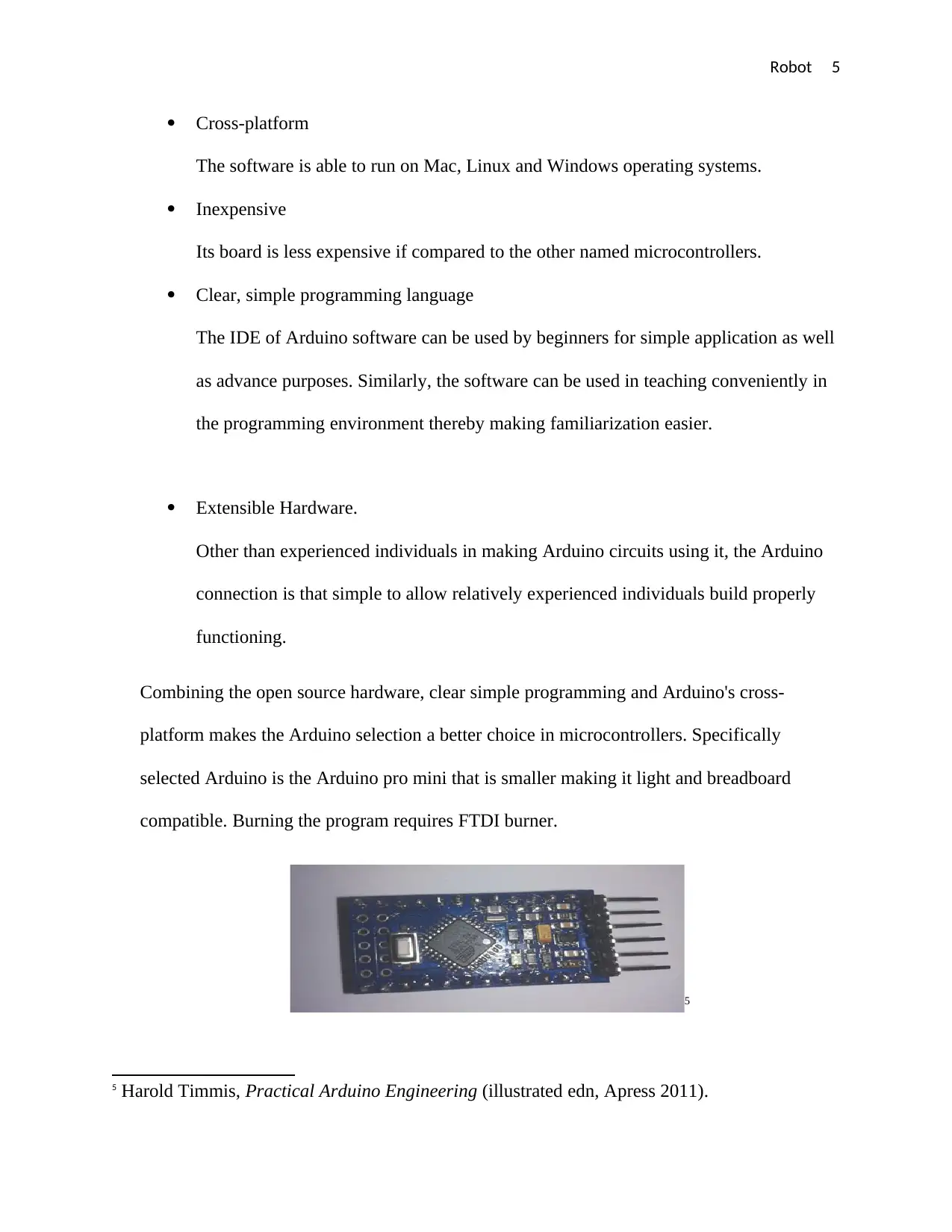
Combining the open source hardware, clear simple programming and Arduino's cross-
platform makes the Arduino selection a better choice in microcontrollers. Specifically
selected Arduino is the Arduino pro mini that is smaller making it light and breadboard
compatible. Burning the program requires FTDI burner.
5
5 Harold Timmis, Practical Arduino Engineering (illustrated edn, Apress 2011).
Cross-platform
The software is able to run on Mac, Linux and Windows operating systems.
Inexpensive
Its board is less expensive if compared to the other named microcontrollers.
Clear, simple programming language
The IDE of Arduino software can be used by beginners for simple application as well
as advance purposes. Similarly, the software can be used in teaching conveniently in
the programming environment thereby making familiarization easier.
Extensible Hardware.
Other than experienced individuals in making Arduino circuits using it, the Arduino
connection is that simple to allow relatively experienced individuals build properly
functioning.
Combining the open source hardware, clear simple programming and Arduino's cross-
platform makes the Arduino selection a better choice in microcontrollers. Specifically
selected Arduino is the Arduino pro mini that is smaller making it light and breadboard
compatible. Burning the program requires FTDI burner.
5
5 Harold Timmis, Practical Arduino Engineering (illustrated edn, Apress 2011).
Robot 6
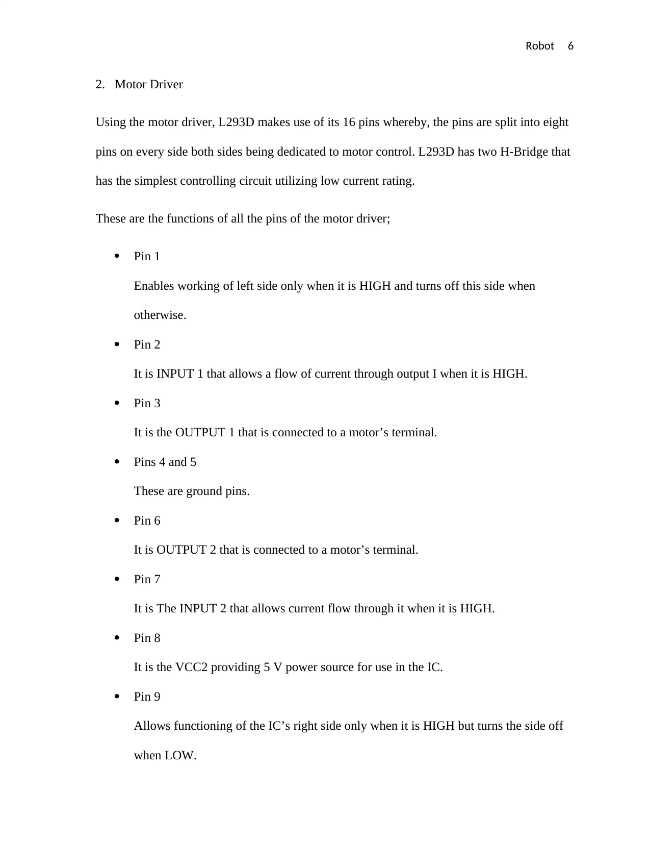
2. Motor Driver
Using the motor driver, L293D makes use of its 16 pins whereby, the pins are split into eight
pins on every side both sides being dedicated to motor control. L293D has two H-Bridge that
has the simplest controlling circuit utilizing low current rating.
These are the functions of all the pins of the motor driver;
Pin 1
Enables working of left side only when it is HIGH and turns off this side when
otherwise.
Pin 2
It is INPUT 1 that allows a flow of current through output I when it is HIGH.
Pin 3
It is the OUTPUT 1 that is connected to a motor’s terminal.
Pins 4 and 5
These are ground pins.
Pin 6
It is OUTPUT 2 that is connected to a motor’s terminal.
Pin 7
It is The INPUT 2 that allows current flow through it when it is HIGH.
Pin 8
It is the VCC2 providing 5 V power source for use in the IC.
Pin 9
Allows functioning of the IC’s right side only when it is HIGH but turns the side off
when LOW.
⊘ This is a preview!⊘
Do you want full access?
Subscribe today to unlock all pages.
Trusted by 1+ million students worldwide
Robot 7
Pin 10
It is the INPUT 3 allowing current flow through it when HIGH.
Pin 11
It is the OUTPUT 3 allowing current flow through it when HIGH.
Pins 12 and 13
These are ground pins.
Pin 14
It is the OUTPUT 4 that is connected to a motor’s terminal.
Pin 15
It is the OUTPUT 4 allowing current flow through it when HIGH.
Pin 16
It is the VCC1 allowing voltage supply to the motor.
The two channels from the motor driver are for operating the chosen 2 motors. Having 2
pairs inbuilt Transistor Darlington as well as a separate supply of power pin that externally
supplies the motors.
6
6Avirup Basu, Intel Edison Projects (1 edn,Packt Publishing Ltd 2017).
Paraphrase This Document
Need a fresh take? Get an instant paraphrase of this document with our AI Paraphraser
Robot 8
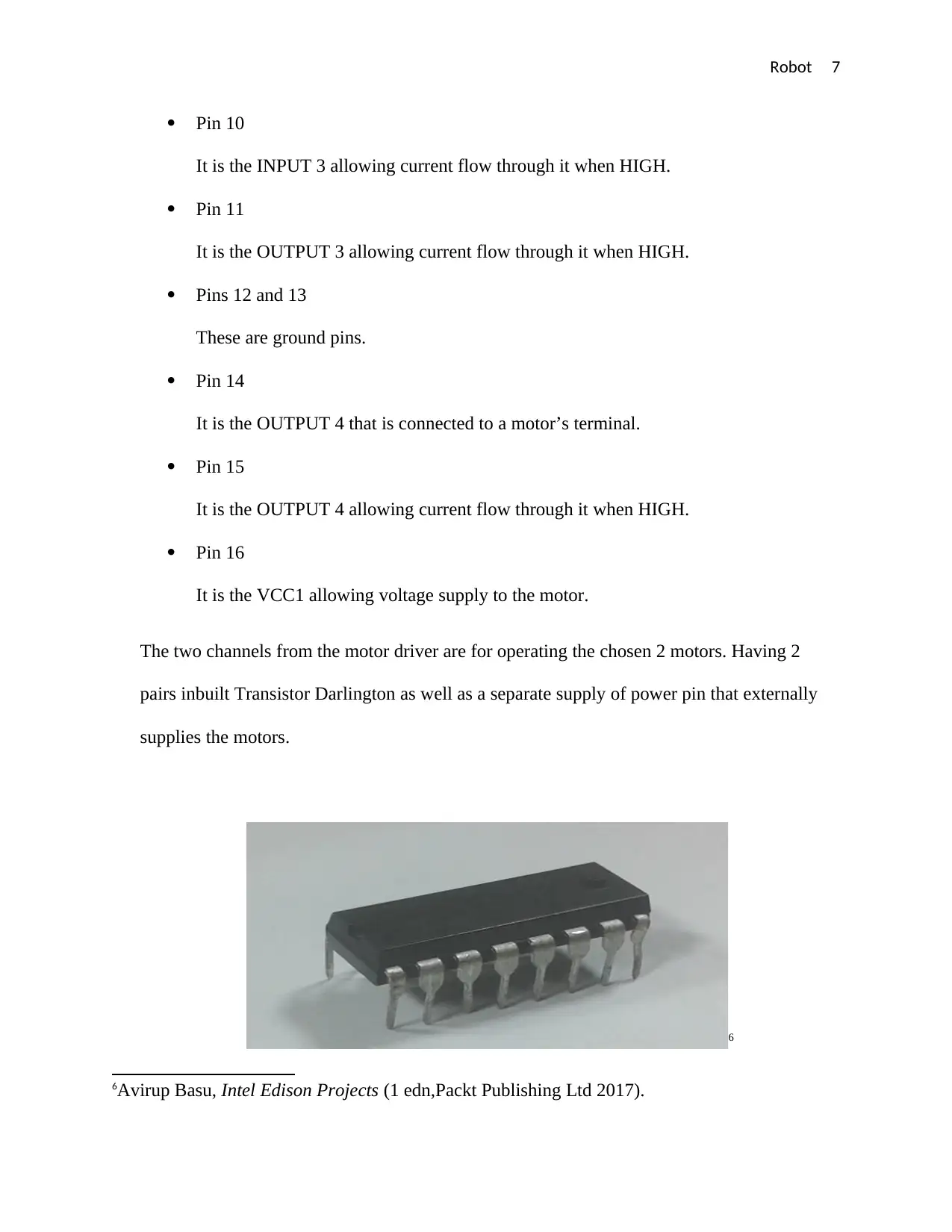
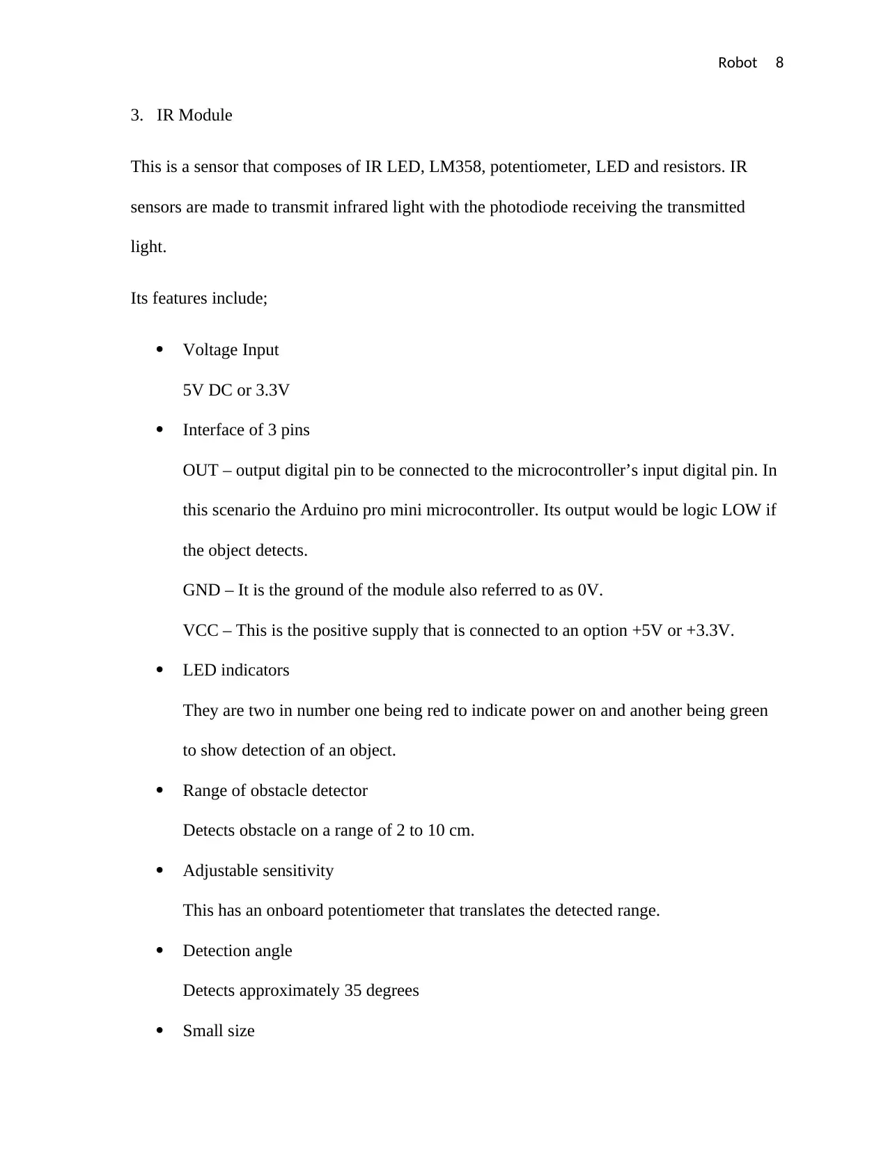
3. IR Module
This is a sensor that composes of IR LED, LM358, potentiometer, LED and resistors. IR
sensors are made to transmit infrared light with the photodiode receiving the transmitted
light.
Its features include;
Voltage Input
5V DC or 3.3V
Interface of 3 pins
OUT – output digital pin to be connected to the microcontroller’s input digital pin. In
this scenario the Arduino pro mini microcontroller. Its output would be logic LOW if
the object detects.
GND – It is the ground of the module also referred to as 0V.
VCC – This is the positive supply that is connected to an option +5V or +3.3V.
LED indicators
They are two in number one being red to indicate power on and another being green
to show detection of an object.
Range of obstacle detector
Detects obstacle on a range of 2 to 10 cm.
Adjustable sensitivity
This has an onboard potentiometer that translates the detected range.
Detection angle
Detects approximately 35 degrees
Small size
Robot 9
Allows its ease incorporation onto a breadboard.
An output of single bits.
Compatibility
The IR module is easy to connect to all microcontroller types.
Dimension
It has a dimension of 3.1 by 1.5 cm.
4. Power Supply
An addition of a voltage regulator would allow development of 5 V for an operation of
Arduino, motor driver as well as the comparator to be implemented in the circuit. Including a
battery voltage source of amount 9 V also enables powering of the circuit.
⊘ This is a preview!⊘
Do you want full access?
Subscribe today to unlock all pages.
Trusted by 1+ million students worldwide
Robot 10
Explanation of circuit
The robot’s design can be split into three sections; control section, sensor section and the driver
section7.
Sensor Section
The sensors in the robot are a composition of a potentiometer, IR diodes, LED and op-amp
comparator. The voltage is referenced at the terminal of the comparator using the potentiometer.
Line sensing is done by the IR sensors that also provide voltage changes at the second terminal
of the comparator. Both voltages at the first and second terminals of the comparator are
compared by the comparator that later produces an output in the digital signal. This robot that
was designed made use of two comparators for the two sensors. The comparator used was LM
358 possessing inbuilt op-amps with low noise (John-David, et al., 2011).
Control Section
The line following process needs a point of control which is the Arduino pro mini. Comparator
outputs would have a connection the Arduino pins 2 and 3 that are digital. The signals would
then be read by the Arduino which send commands driving the line follower to the driver circuit
(Richard, 2014).
7 Richard Grimmett, Arduino Robotic Projects (reprint edn, Packt Publishing Ltd 2014).
Paraphrase This Document
Need a fresh take? Get an instant paraphrase of this document with our AI Paraphraser
Robot 11
Driver Section
Sections found in the driver sections include; 2 DC motors and motor driver. The motor driver
drives the motors in the robot since the voltage supplied by the Arduino as well as the current
would not be enough. These motor drivers then produce ample voltage and current to the motors.
However, sending such voltages to the motors would firstly depend on the commands from the
Arduino8.
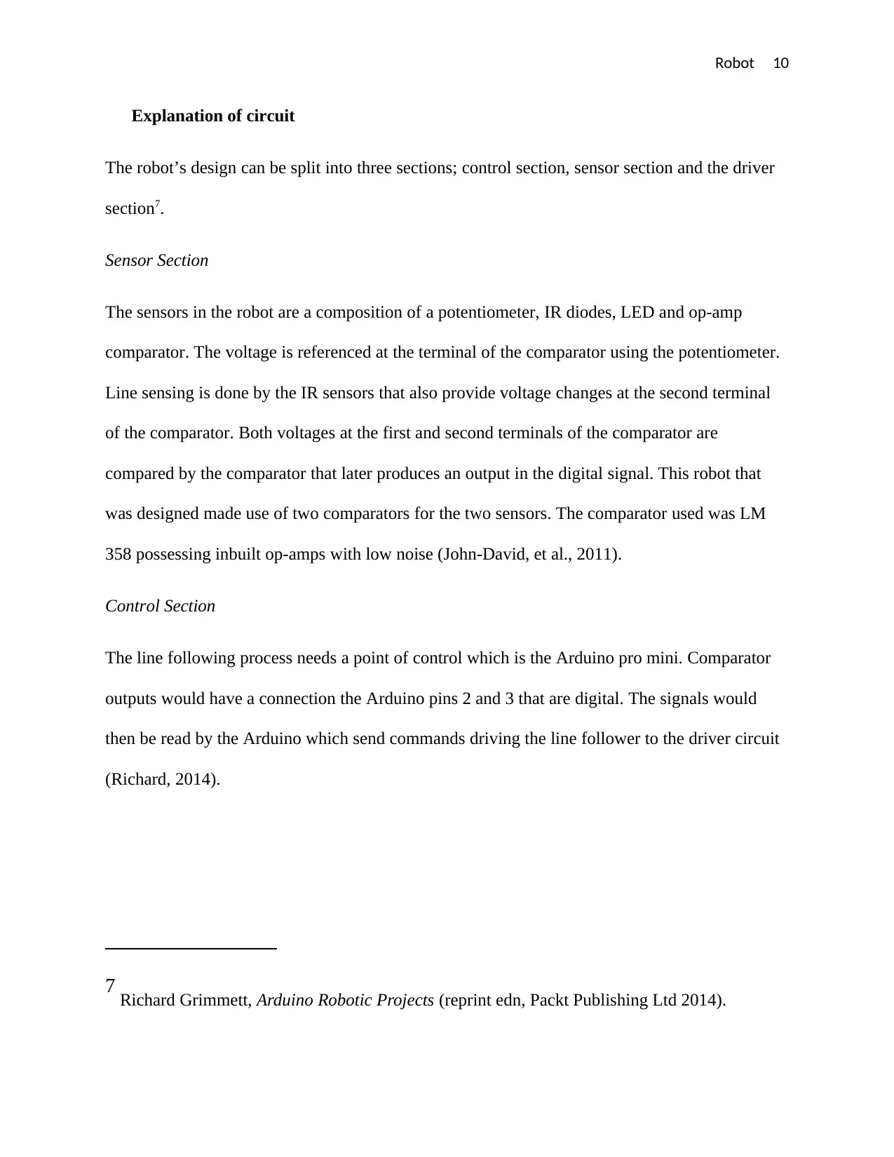
Working
Once the robot senses a black line, the signal generated from comparator would be sent to the
Arduino. The Arduino being the controller makes a command and sends it to the motor driver
that would drive the robot's motors in accordance with the output from the sensor (Richard,
2014).
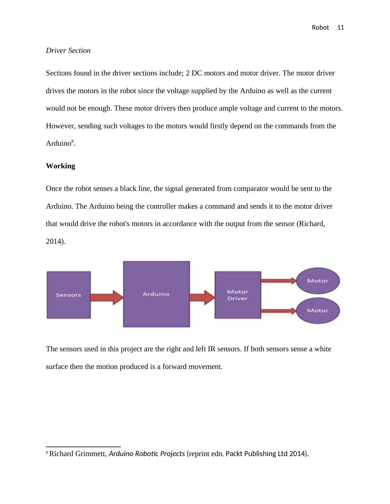
The sensors used in this project are the right and left IR sensors. If both sensors sense a white
surface then the motion produced is a forward movement.
8 Richard Grimmett, Arduino Robotic Projects (reprint edn, Packt Publishing Ltd 2014).
Driver Section
Sections found in the driver sections include; 2 DC motors and motor driver. The motor driver
drives the motors in the robot since the voltage supplied by the Arduino as well as the current
would not be enough. These motor drivers then produce ample voltage and current to the motors.
However, sending such voltages to the motors would firstly depend on the commands from the
Arduino8.
Working
Once the robot senses a black line, the signal generated from comparator would be sent to the
Arduino. The Arduino being the controller makes a command and sends it to the motor driver
that would drive the robot's motors in accordance with the output from the sensor (Richard,
2014).
The sensors used in this project are the right and left IR sensors. If both sensors sense a white
surface then the motion produced is a forward movement.
8 Richard Grimmett, Arduino Robotic Projects (reprint edn, Packt Publishing Ltd 2014).
Robot 12
In case the left sensor senses a black surface, the resulting motion would be to turn left.
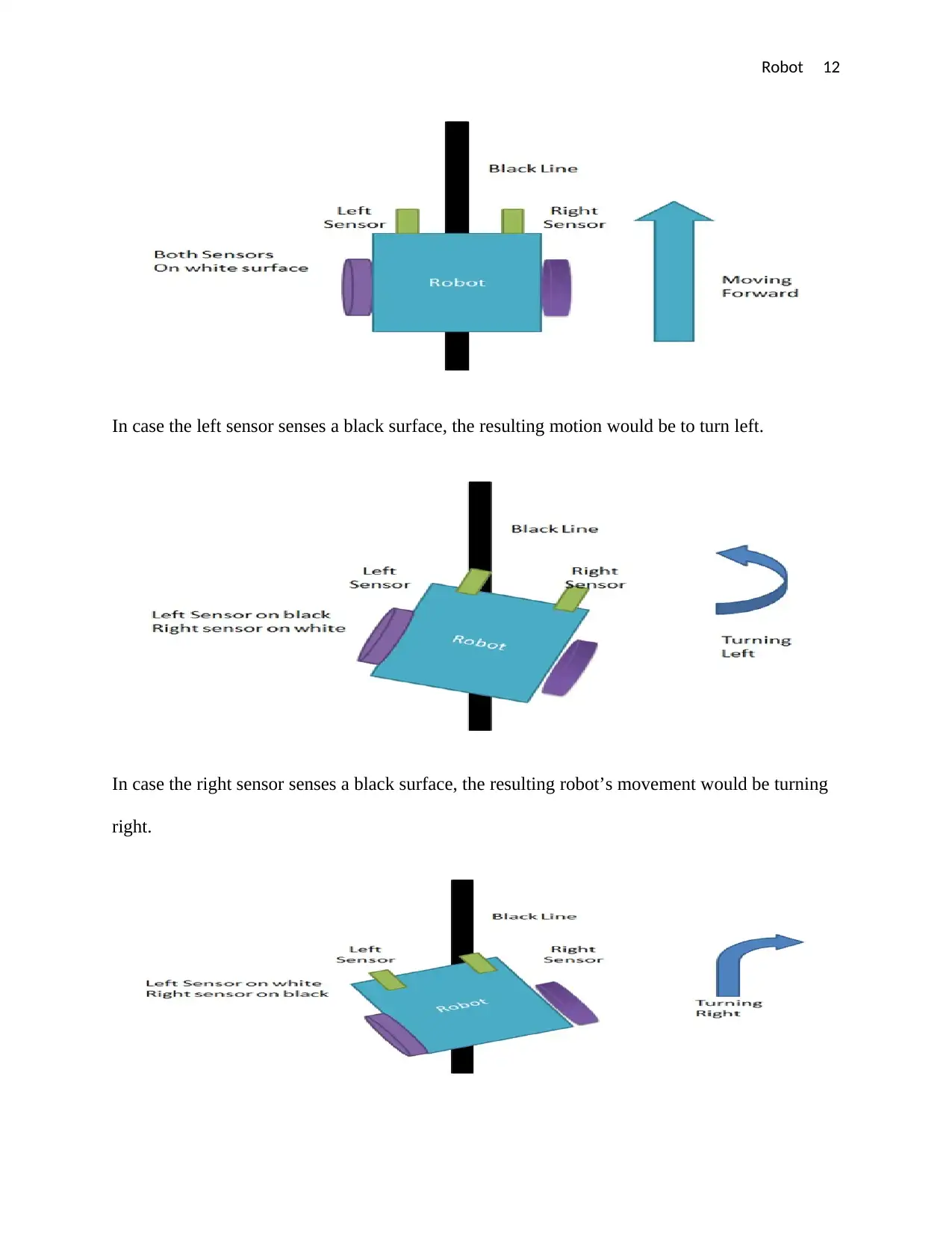
In case the right sensor senses a black surface, the resulting robot’s movement would be turning
right.
In case the left sensor senses a black surface, the resulting motion would be to turn left.
In case the right sensor senses a black surface, the resulting robot’s movement would be turning
right.
⊘ This is a preview!⊘
Do you want full access?
Subscribe today to unlock all pages.
Trusted by 1+ million students worldwide
1 out of 22

Your All-in-One AI-Powered Toolkit for Academic Success.
+13062052269
info@desklib.com
Available 24*7 on WhatsApp / Email
![[object Object]](/_next/static/media/star-bottom.7253800d.svg)
Unlock your academic potential
Copyright © 2020–2025 A2Z Services. All Rights Reserved. Developed and managed by ZUCOL.