Wireless Link Budget Estimation for Advanced Wireless Networks
VerifiedAdded on 2023/04/25
|6
|693
|53
AI Summary
Performing link budget estimation to find out the minimum transmission power required by the transmission station for maximum transmission speed in the entire area. Learn about obstacles, Fresnel zone radius, and link margin value.
Contribute Materials
Your contribution can guide someone’s learning journey. Share your
documents today.
Advanced Wireless Networks
Wireless link Budget Estimation
Student name
Student registration number
Date of submission
1/28/2019
Wireless link Budget Estimation
Student name
Student registration number
Date of submission
1/28/2019
Secure Best Marks with AI Grader
Need help grading? Try our AI Grader for instant feedback on your assignments.
TASK I
Performing link budget estimation to find out the minimum transmission power required by the
transmission station for maximum transmission speed in the entire area.
Assumption:
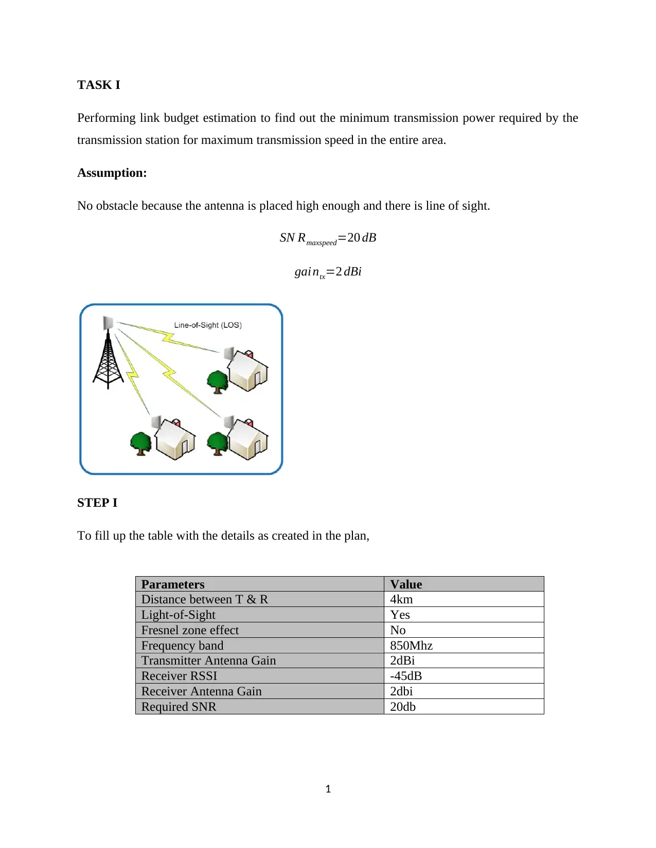
No obstacle because the antenna is placed high enough and there is line of sight.
SN Rmaxspeed=20 dB
gai ntx=2 dBi
STEP I
To fill up the table with the details as created in the plan,
1
Parameters Value
Distance between T & R 4km
Light-of-Sight Yes
Fresnel zone effect No
Frequency band 850Mhz
Transmitter Antenna Gain 2dBi
Receiver RSSI -45dB
Receiver Antenna Gain 2dbi
Required SNR 20db
To obtain the receiver RSSI- the linear measurement of how good the radio signal is between the
RC transmitter and receiver. It is the received signal strength indication- a safety feature critical
to a WWAN deployment in a new suburb.
EIGRP=PT −Lc+Ga
EIGRP=PT −0+2 dBi
To determine the Fresnel zone radius,
R ( mtrs ) =17.31∗ √ D ( ¿ km )
4 f ( GHz )
¿ 17.31∗ √ 4
4∗0.85 =18.7753 m
R=18.7753m
STEP II
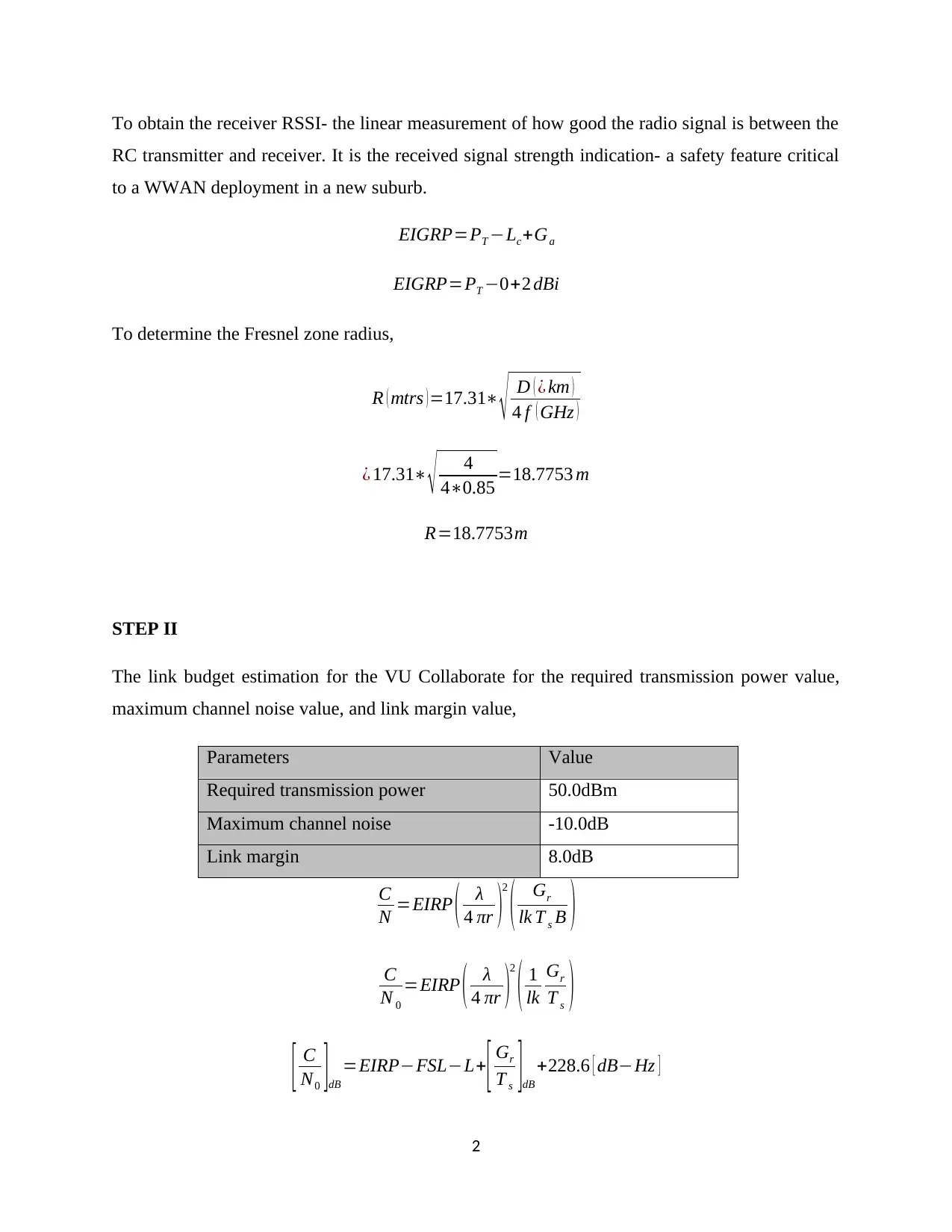
The link budget estimation for the VU Collaborate for the required transmission power value,
maximum channel noise value, and link margin value,
Parameters Value
Required transmission power 50.0dBm
Maximum channel noise -10.0dB
Link margin 8.0dB
C
N =EIRP ( λ
4 πr )2
( Gr
lk T s B )
C
N 0
=EIRP ( λ
4 πr )2
( 1
lk
Gr
T s )
[ C
N0 ]dB
=EIRP−FSL−L+
[ Gr
T s ]dB
+228.6 [ dB−Hz ]
2
[ C
N ]dB
=EIRP−FSL−L+
[ Gr
T s ]dB
+228.6−10 log (B)
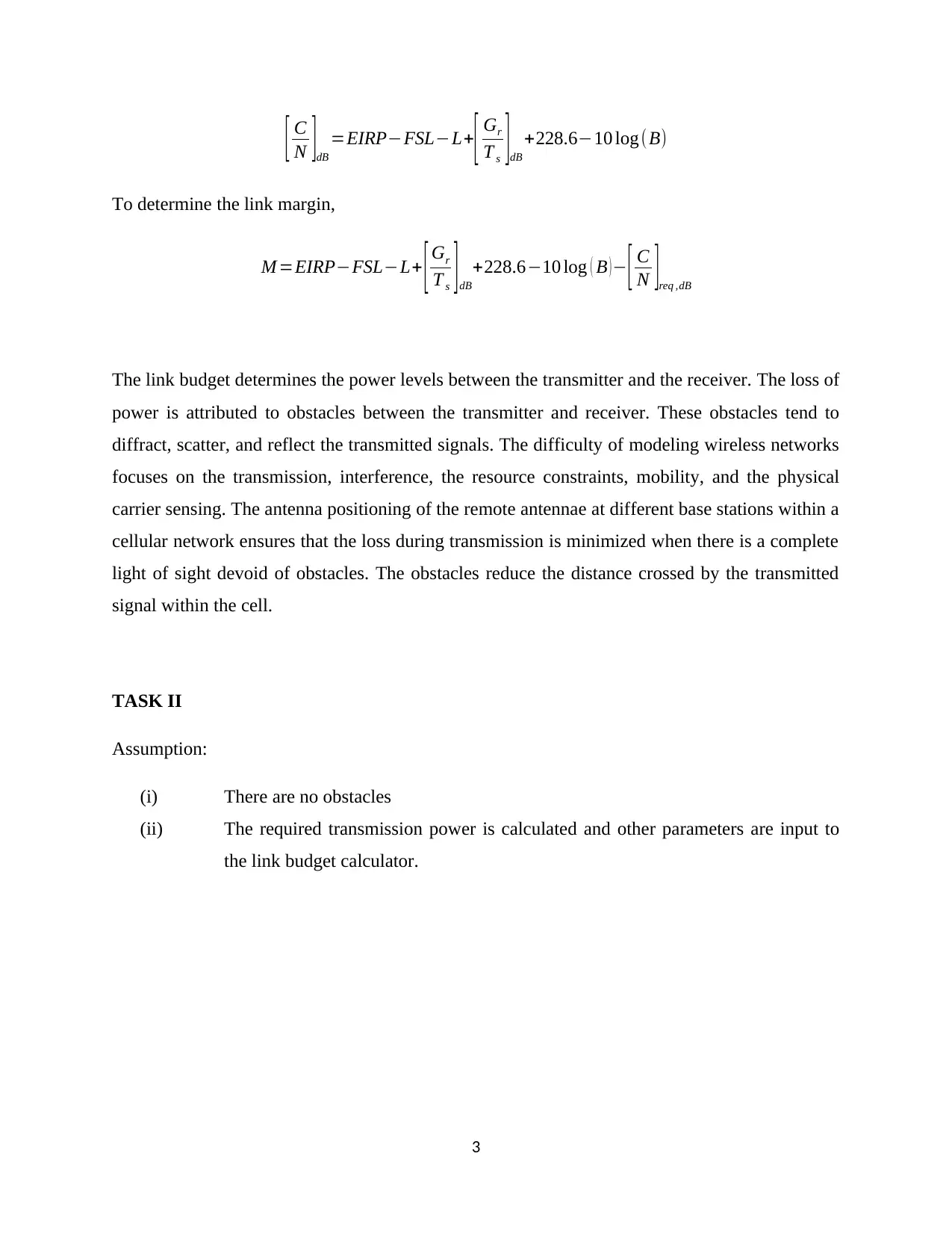
To determine the link margin,
M =EIRP−FSL−L+ [ Gr
T s ]dB
+228.6−10 log ( B )− [ C
N ]req ,dB
The link budget determines the power levels between the transmitter and the receiver. The loss of
power is attributed to obstacles between the transmitter and receiver. These obstacles tend to
diffract, scatter, and reflect the transmitted signals. The difficulty of modeling wireless networks
focuses on the transmission, interference, the resource constraints, mobility, and the physical
carrier sensing. The antenna positioning of the remote antennae at different base stations within a
cellular network ensures that the loss during transmission is minimized when there is a complete
light of sight devoid of obstacles. The obstacles reduce the distance crossed by the transmitted
signal within the cell.
TASK II
Assumption:
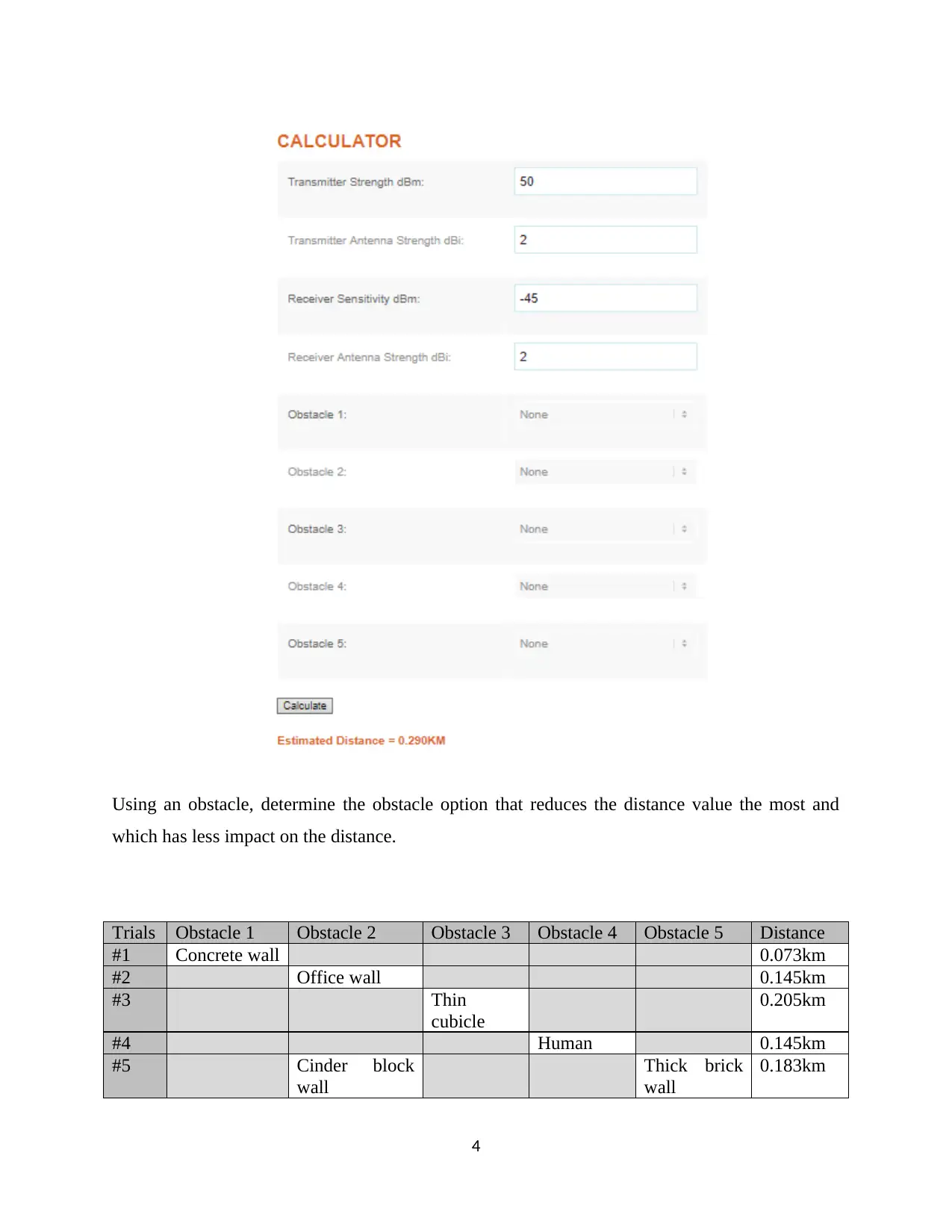
(i) There are no obstacles
(ii) The required transmission power is calculated and other parameters are input to
the link budget calculator.
3
Paraphrase This Document
Need a fresh take? Get an instant paraphrase of this document with our AI Paraphraser
Using an obstacle, determine the obstacle option that reduces the distance value the most and
which has less impact on the distance.
Trials Obstacle 1 Obstacle 2 Obstacle 3 Obstacle 4 Obstacle 5 Distance
#1 Concrete wall 0.073km
#2 Office wall 0.145km
#3 Thin
cubicle
0.205km
#4 Human 0.145km
#5 Cinder block
wall
Thick brick
wall
0.183km
4
which has less impact on the distance.
Trials Obstacle 1 Obstacle 2 Obstacle 3 Obstacle 4 Obstacle 5 Distance
#1 Concrete wall 0.073km
#2 Office wall 0.145km
#3 Thin
cubicle
0.205km
#4 Human 0.145km
#5 Cinder block
wall
Thick brick
wall
0.183km
4
The thin cubicle reduces the distance with the largest magnitude. The wireless stations or
nodes tend to communicate over a wireless medium. The network operates under infrastructure
and its operation is limited as there is no infrastructure support in between the transmitter and
receiver. The obstacles are of different forms and they affect the distance travelled by the
transmitted signal by a given distance.
The obstacle that blocked the system most is the thin cubicle, obstacle #3. The other
obstacles listed are thin and thick brick walls, office wall, thin plaster wall, cinder block wall,
concrete wall, window in brick wall, metal door, thin cubicle and a human obstacle. These
obstacles are of different magnitude and they affect the system in different ways reducing the
distance travelled by the transmitted signal.
5
1 out of 6
Your All-in-One AI-Powered Toolkit for Academic Success.
+13062052269
info@desklib.com
Available 24*7 on WhatsApp / Email
Unlock your academic potential
© 2024 | Zucol Services PVT LTD | All rights reserved.