Fluid Mechanics: Turbine and Pump Efficiency Calculation Report
VerifiedAdded on 2023/04/22
|8
|1720
|66
Report
AI Summary
This report delves into the operational characteristics and efficiencies of various hydraulic turbines, including Pelton wheel, Francis turbine, and axial flow turbines, considering their ecological impact and limitations. It calculates the hydraulic and overall efficiencies for a Kaplan turbine based on provided data, including hydraulic head, frictional losses, and flow rate. Furthermore, the report examines the power requirements of centrifugal pumps, calculating the power needed to pump water under different conditions, considering pump efficiency. Finally, it identifies the most suitable pump installation in terms of ecological impact, emphasizing the importance of water resource management and energy consumption. Desklib provides access to similar solved assignments and study resources for students.
First Name Last Name
Instructor
Civil Engineering
17 January 2019
Fluid Mechanics
Part a: LO4 - Explore the operating principles and efficiencies of hydraulic machines
1.0 Task 1
1.1 Explain the operational characteristics of the Pelton Wheel, Francis &
axial flow types of turbine to include:
1.1.1. The efficiency of each device.
a. Pelton wheel
Overall efficiency of a Pelton wheel turbine at optimum is determined by
two specific factors, namely; its speed ratio, and its specific speed. For
instance, a single jet Pelton wheel turbine has a specific speed ranging
from 4-16. Hence, the ratio of D/d varies between 6 and 26. When the
value of D/d is larger, the revolutions per minute rpm is reduced and so is
the mechanical efficiency of the wheel. A lower value of D/d increases the
Pelton wheel specific speed but as a result there will be reduced efficiency
for the reason that the spacing of buckets will be close. To maintain an
optimum efficiency, a specific number of buckets, n are required and is
determined from the empirical relation as shown:
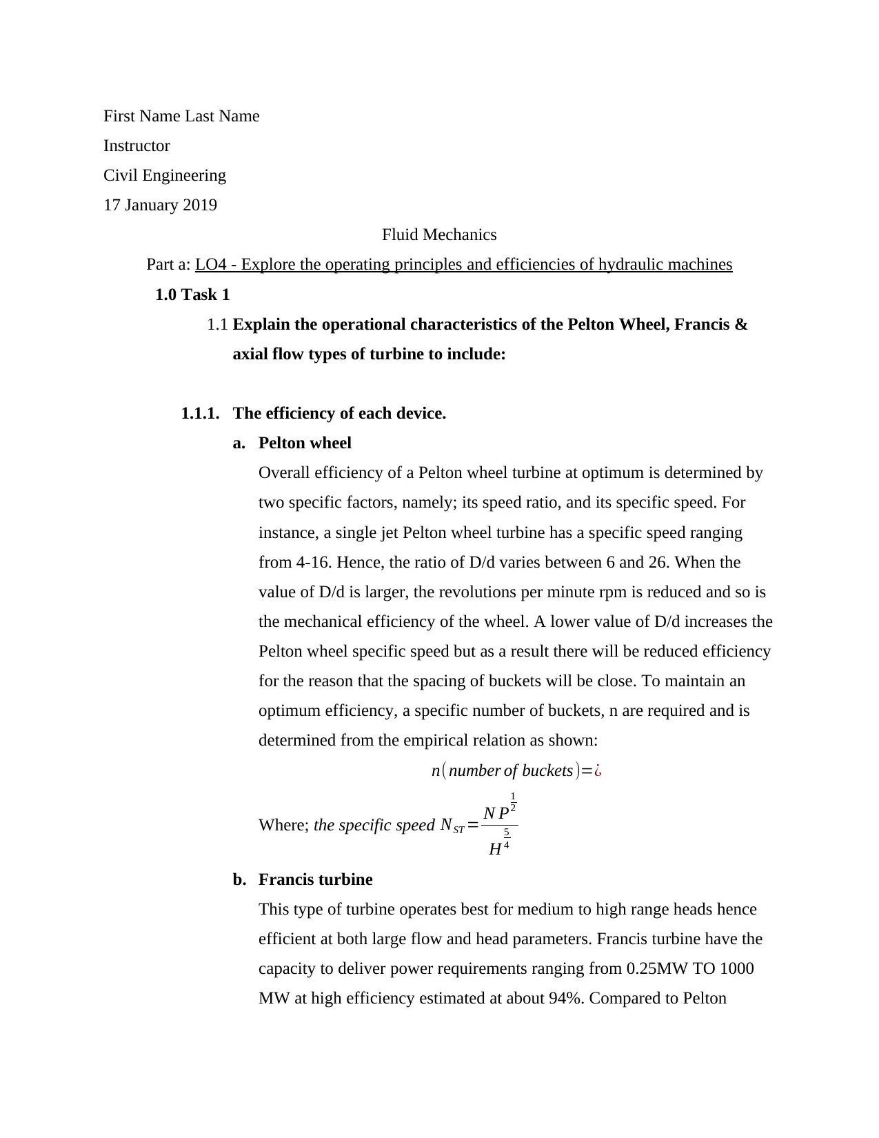
n( number of buckets)=¿
Where; the specific speed NST = N P
1
2
H
5
4
b. Francis turbine
This type of turbine operates best for medium to high range heads hence
efficient at both large flow and head parameters. Francis turbine have the
capacity to deliver power requirements ranging from 0.25MW TO 1000
MW at high efficiency estimated at about 94%. Compared to Pelton
Paraphrase This Document
Need a fresh take? Get an instant paraphrase of this document with our AI Paraphraser
Last Name 2
wheel, Francis turbine is superior especially given that it is more
economical, more resistant to wear and has a higher level of efficiency
than Pelton wheel turbine. However, decreased flow in Francis turbine
significantly increases risks of cavitation which as a result can reduce its
efficiency by up to 40%.
c. Axial flow types of turbine
Stage configuration in axial flow turbines also known as degree of
reaction is not a factor of losses in the pump. Higher reaction however
means increased efficiency, an indication of less work per stage
distributed over a number of stages for a given overall pressure ratio. The
choice of configuring is determined from prior understanding of the losses
and their control so as to ensure increased efficiency. These losses include
but not limited to shock losses, mixing loses, three dimensional effects
like leakage flows, and viscous losses.
1.1.2. The ecological impact of each device.
I. Pelton wheel
Suitable in both high and low yield water areas and is likely not to
affect water table balance. Pelton wheel turbine are more exposed
to wear and hence can result in water resource losses and pollution
when before and during implementation of the needed repairs.
II. Francis turbine
Since they operate at medium to large to heads, they are unsuitable
in places where water resource reserves are scarce and when
applied can significantly destabilize the water table. In places
where the water resource reserves are adequate to support the
heads, leakages and poor maintenance might result to a lot of
losses through spillage posing consequences of erosion, flooding
etc.
III. Axial flow types of turbine
They present serious ecological consequences for instance when
there is axial flow misalignment on a tidal turbine and hydrokinetic
Last Name 3
turbines where huge losses and pollution have been noted in a
number cases in the past.
1.1.3. The limitations of each type of device.
a. Pelton wheel
The Pelton wheel is competent and dependable while working under vast
heads. To produce a given yield power under a littler head, the flow rate
through the turbine must be higher which requires an expansion in the
stream width/ jet diameter. The jets are typically constrained to 4 or 6 for
every wheel. The increments in diameter of the jet thus proliferates the
diameter of the wheel. Along these lines the machine turns out to be
unduly huge, massive and moderate running. Practically speaking,
turbines of the reaction type are progressively reasonable for lower heads.
b. Francis turbine
The effect of water hammer which results when the runners are forced to
stopping from high speed causes overpressures build up posing
catastrophic consequences. Also unlike Pelton wheel, Francis turbine is
largely restricted to large scale hydroelectric systems. They also have low
acceptance of head variation and risks cavitation as a consequence of
runner erosion or/ and efficiency losses.
c. Axial flow types of turbine
Axial flow turbine has a notably very high maintenance costs, elevated
velocity of water flows could result to cavitation, water leakage into the
pump in general limits its use, application and efficiency.
An axial flow type (Kaplan) turbine is chosen for analysis and you have been asked to:
1.1. Calculate the hydraulic and overall efficiencies for the chosen turbine using the
sample data below.
Hydraulic head 30 m
⊘ This is a preview!⊘
Do you want full access?
Subscribe today to unlock all pages.

Trusted by 1+ million students worldwide
Last Name 4
Frictional head loss 5 %
Volumetric flow rate 2.0 m3 s-1
Runner velocity 120 R.P.M.
Mean runner diameter 1.5 m
Runner blade angle 25O
Runner friction 8 %
Guide vane outlet angle 30O
Power requirements (500 homes) 0.5 MW
Solution:
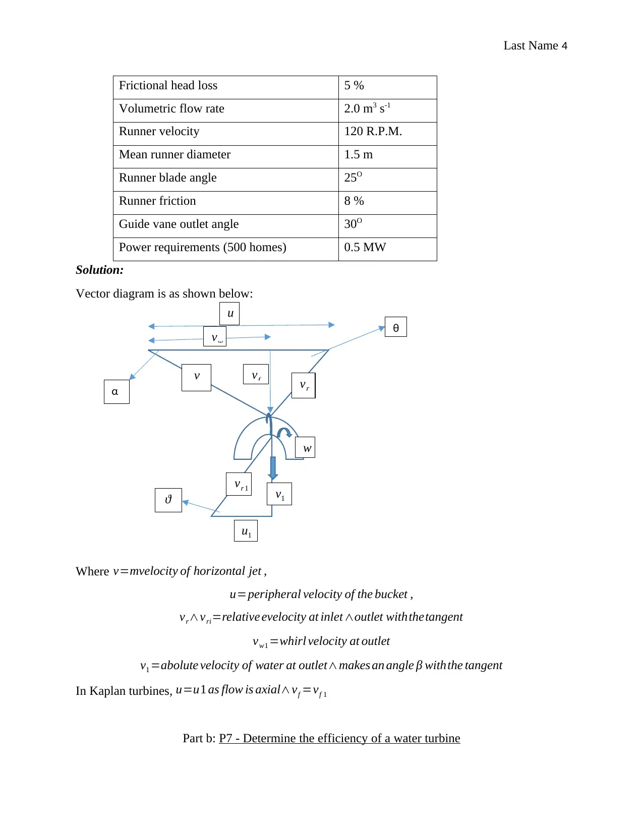
Vector diagram is as shown below:
Where v=mvelocity of horizontal jet ,
u=peripheral velocity of the bucket ,
vr∧vri=relative evelocity at inlet∧outlet withthetangent
vw1 =whirl velocity at outlet
v1 =abolute velocity of water at outlet∧makes an angle β withthe tangent
In Kaplan turbines, u=u1 as flow is axial∧vf =vf 1
Part b: P7 - Determine the efficiency of a water turbine
u
vw
vr
v vf
w
α
ϑ
θ
vr 1 v1
u1
Paraphrase This Document
Need a fresh take? Get an instant paraphrase of this document with our AI Paraphraser
Last Name 5
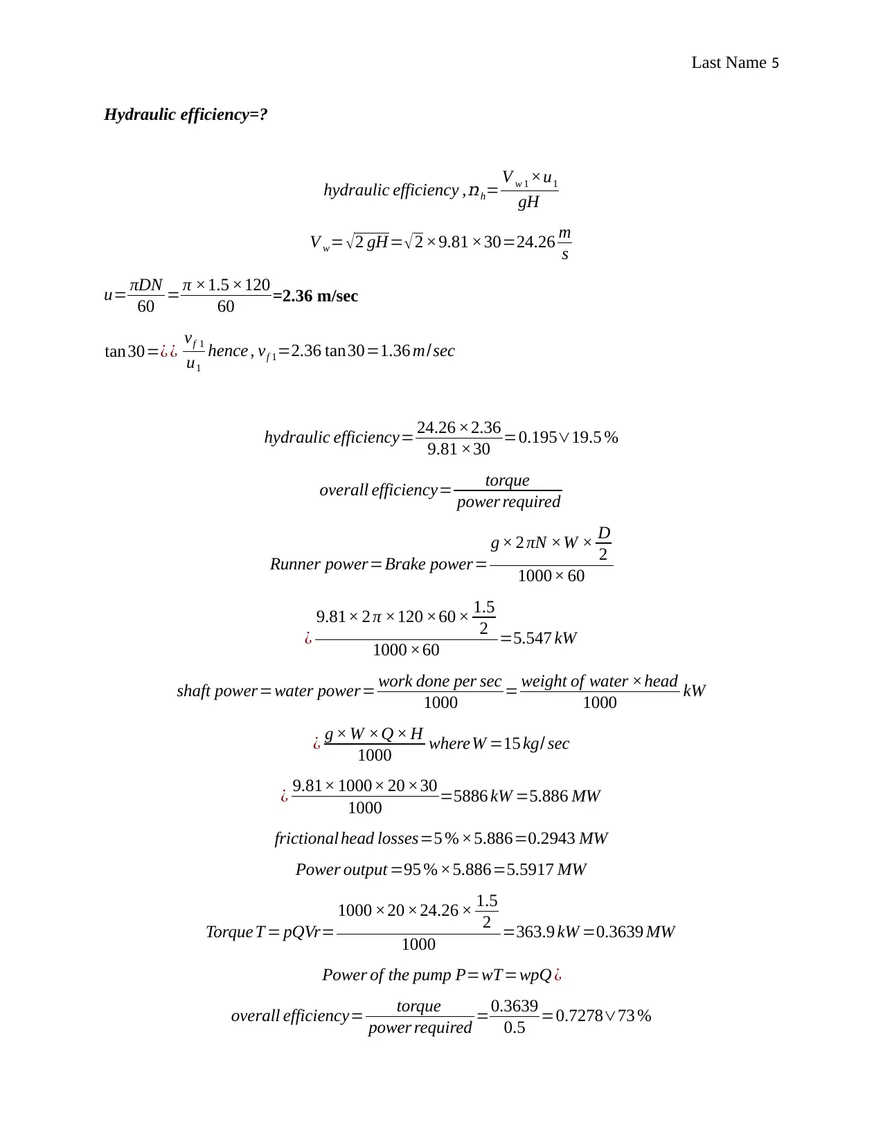
Hydraulic efficiency=?
hydraulic efficiency , ռh= V w 1 ×u1
gH
V w= √2 gH = √2 ×9.81 ×30=24.26 m
s
u= πDN
60 = π ×1.5 ×120
60 =2.36 m/sec
tan30=¿ ¿ vf 1
u1
hence , vf 1=2.36 tan30=1.36 m/sec
hydraulic efficiency= 24.26 ×2.36
9.81 ×30 =0.195∨19.5 %
overall efficiency= torque
power required
Runner power=Brake power=
g × 2 πN ×W × D
2
1000× 60
¿
9.81× 2 π ×120 ×60 × 1.5
2
1000 ×60 =5.547 kW
shaft power=water power= work done per sec
1000 = weight of water ×head
1000 kW
¿ g × W ×Q × H
1000 whereW =15 kg/ sec
¿ 9.81× 1000× 20 ×30
1000 =5886 kW =5.886 MW
frictional head losses=5 % ×5.886=0.2943 MW
Power output =95 %×5.886=5.5917 MW
Torque T = pQVr=
1000 ×20 ×24.26 × 1.5
2
1000 =363.9 kW =0.3639 MW
Power of the pump P=wT=wpQ ¿
overall efficiency= torque
power required =0.3639
0.5 =0.7278∨73 %
Last Name 6
Part c: P8 - Calculate the input power requirements of centrifugal pumps
To maintain the required head, a centrifugal pump uses stored energy to pump the
working fluid back to a reservoir. You need to:
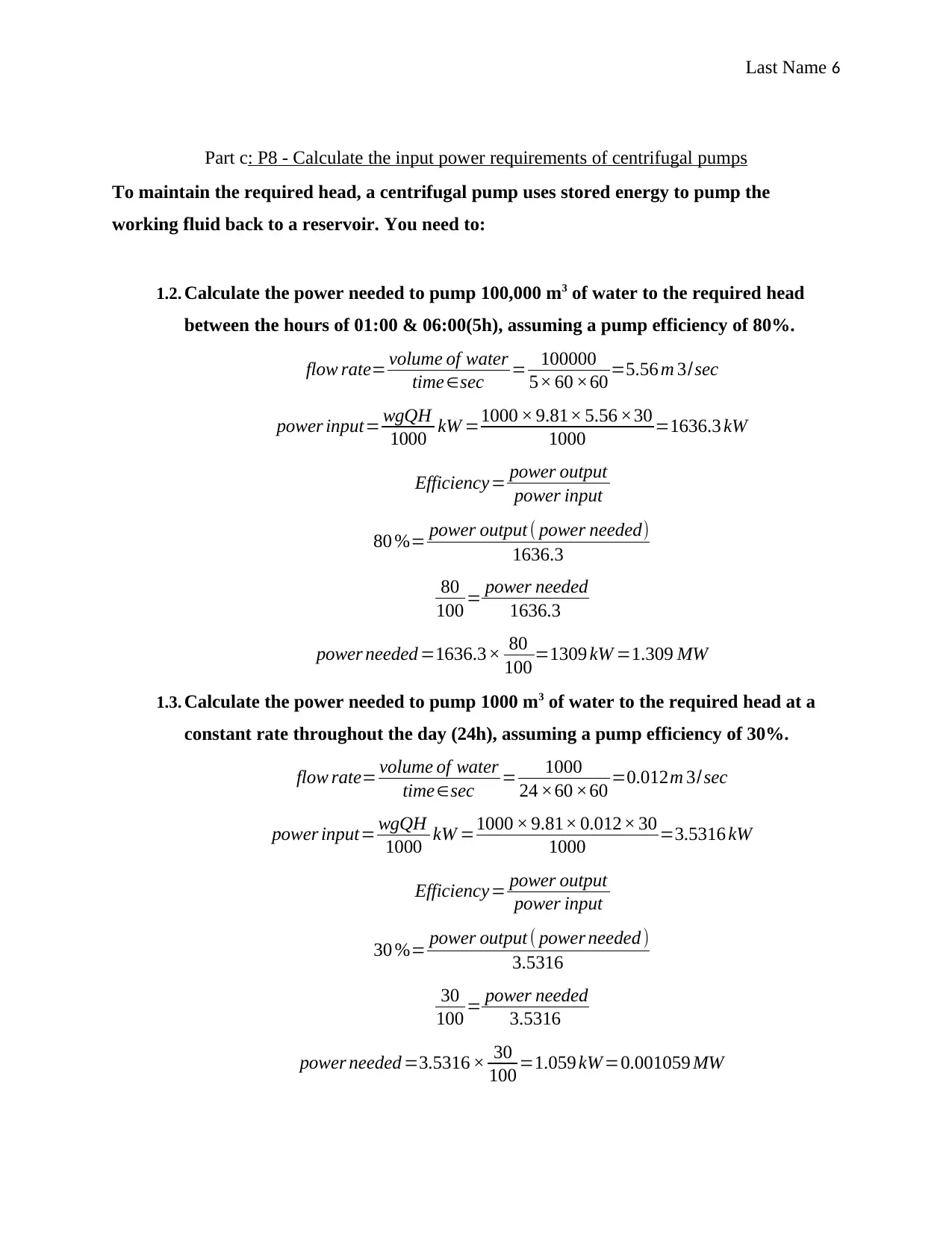
1.2. Calculate the power needed to pump 100,000 m3 of water to the required head
between the hours of 01:00 & 06:00(5h), assuming a pump efficiency of 80%.
flow rate= volume of water
time∈sec = 100000
5× 60 ×60 =5.56 m 3/sec
power input= wgQH
1000 kW =1000 × 9.81× 5.56 ×30
1000 =1636.3 kW
Efficiency= power output
power input
80 %= power output ( power needed)
1636.3
80
100 = power needed
1636.3
power needed =1636.3× 80
100 =1309 kW =1.309 MW
1.3. Calculate the power needed to pump 1000 m3 of water to the required head at a
constant rate throughout the day (24h), assuming a pump efficiency of 30%.
flow rate= volume of water
time∈sec = 1000
24 ×60 ×60 =0.012m 3/sec
power input= wgQH
1000 kW =1000 × 9.81× 0.012× 30
1000 =3.5316 kW
Efficiency= power output
power input
30 %= power output ( power needed )
3.5316
30
100 = power needed
3.5316
power needed =3.5316 × 30
100 =1.059 kW =0.001059 MW
⊘ This is a preview!⊘
Do you want full access?
Subscribe today to unlock all pages.

Trusted by 1+ million students worldwide
Last Name 7
1.4. Identify which pump installation is most suitable in regard to ecological impact.
The second pump running continually throughout the day pumping 1000 m3 of water is
suitable compared to the former running for 5 hours pumping 100000 m3 . Even though
it has a much lower efficiency, the rate of water resource depletion is much less.
Additionally, it uses less energy inform of power to pump water hence less ecologically
impactful. It therefore allows for a better rate of water resource exploitation as well as
energy used compared with the first pump.
Paraphrase This Document
Need a fresh take? Get an instant paraphrase of this document with our AI Paraphraser
Last Name 8
Bibliography
R. Aungier, “Aerodynamic Performance Analysis of Axial-Flow Turbines,” Turbine
Aerodynamics: Axial-Flow and Radial-Flow Turbine Design and Analysis, 2015, pp. 93–
131.
P. Bates, S. Lane, and R. Ferguson. (2009, February 06) “Computational Fluid Dynamics
Modelling for Environmental ...,” [Online]. Available:
http://onlinelibrary.wiley.com/doi/10.1002/0470015195.ch1/summary . [Accessed: 18-
Jan-2019].
“Efficiency Analyses for Small Hydro Power Plant with Francis Turbine,” International
Journal of Modern Trends in Engineering & Research, vol. 4, no. 10, 2017, pp. 155–
164.
G. H. Mittendorf, “Closure to ‘Discussion of ‘Field Observations of Transient
Servopressures in Kaplan Turbines’’ (1967, ASME J. Eng. Power, 89, p. 546),” Journal
of Engineering for Gas Turbines and Power, vol. 89, no. 4, 1967, pp. 540–545.
F. M. White, “Hydraulic machines and pumps,” in Fluid mechanics. New Delhi, India:
McGraw-Hill Education (India), 2017, pp. 166-389.
1 out of 8
Your All-in-One AI-Powered Toolkit for Academic Success.
+13062052269
info@desklib.com
Available 24*7 on WhatsApp / Email
![[object Object]](/_next/static/media/star-bottom.7253800d.svg)
Unlock your academic potential
Copyright © 2020–2025 A2Z Services. All Rights Reserved. Developed and managed by ZUCOL.