Local Area Network (LAN) Design and Implementation for Football Field Marketing Ltd.
VerifiedAdded on 2024/06/07
|55
|6554
|219
AI Summary
This report explores the design and implementation of a Local Area Network (LAN) for Football Field Marketing Ltd., a company with 28 employees across three floors. It critically evaluates different LAN technologies, analyzes traffic-intensive services, and discusses security concerns. The report includes a detailed LAN design, component evaluation, and implementation steps, including VLAN configuration, firewall implementation, and network security measures. It also presents a critical review and testing of the LAN using ping tests and Packet Tracer simulations. The report concludes with recommendations for improving network security, reliability, and performance.
Contribute Materials
Your contribution can guide someone’s learning journey. Share your
documents today.

Local Area Network
Secure Best Marks with AI Grader
Need help grading? Try our AI Grader for instant feedback on your assignments.
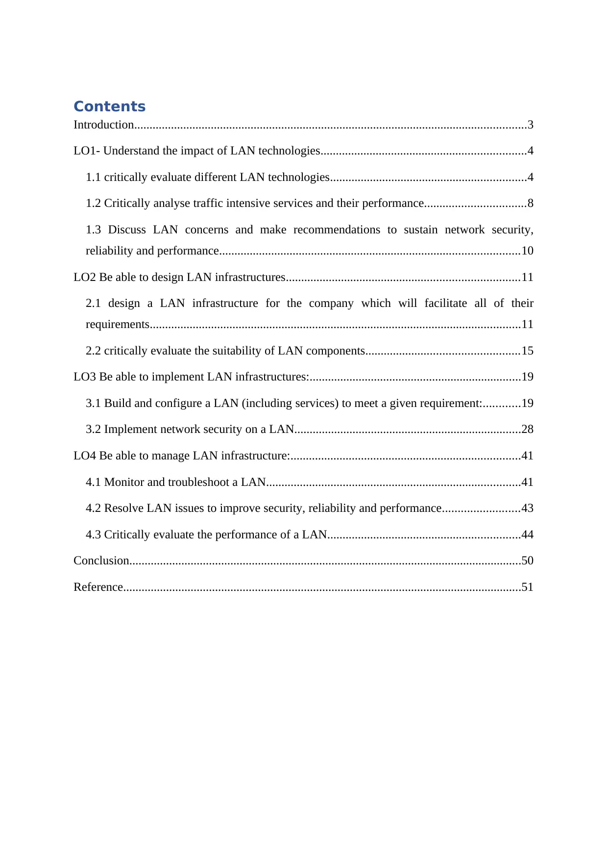
Contents
Introduction................................................................................................................................3
LO1- Understand the impact of LAN technologies...................................................................4
1.1 critically evaluate different LAN technologies................................................................4
1.2 Critically analyse traffic intensive services and their performance.................................8
1.3 Discuss LAN concerns and make recommendations to sustain network security,
reliability and performance..................................................................................................10
LO2 Be able to design LAN infrastructures............................................................................11
2.1 design a LAN infrastructure for the company which will facilitate all of their
requirements.........................................................................................................................11
2.2 critically evaluate the suitability of LAN components..................................................15
LO3 Be able to implement LAN infrastructures:.....................................................................19
3.1 Build and configure a LAN (including services) to meet a given requirement:............19
3.2 Implement network security on a LAN..........................................................................28
LO4 Be able to manage LAN infrastructure:...........................................................................41
4.1 Monitor and troubleshoot a LAN...................................................................................41
4.2 Resolve LAN issues to improve security, reliability and performance.........................43
4.3 Critically evaluate the performance of a LAN...............................................................44
Conclusion................................................................................................................................50
Reference..................................................................................................................................51
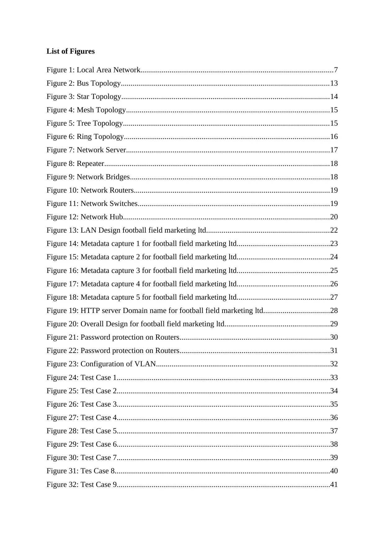
List of Figures
Figure 1: Local Area Network...................................................................................................7
Figure 2: Bus Topology...........................................................................................................13
Figure 3: Star Topology...........................................................................................................14
Figure 4: Mesh Topology.........................................................................................................15
Figure 5: Tree Topology..........................................................................................................15
Figure 6: Ring Topology..........................................................................................................16
Figure 7: Network Server.........................................................................................................17
Figure 8: Repeater....................................................................................................................18
Figure 9: Network Bridges.......................................................................................................18
Figure 10: Network Routers.....................................................................................................19
Figure 11: Network Switches...................................................................................................19
Figure 12: Network Hub..........................................................................................................20
Figure 13: LAN Design football field marketing ltd...............................................................22
Figure 14: Metadata capture 1 for football field marketing ltd................................................23
Figure 15: Metadata capture 2 for football field marketing ltd................................................24
Figure 16: Metadata capture 3 for football field marketing ltd................................................25
Figure 17: Metadata capture 4 for football field marketing ltd................................................26
Figure 18: Metadata capture 5 for football field marketing ltd................................................27
Figure 19: HTTP server Domain name for football field marketing ltd..................................28
Figure 20: Overall Design for football field marketing ltd......................................................29
Figure 21: Password protection on Routers.............................................................................30
Figure 22: Password protection on Routers.............................................................................31
Figure 23: Configuration of VLAN.........................................................................................32
Figure 24: Test Case 1..............................................................................................................33
Figure 25: Test Case 2..............................................................................................................34
Figure 26: Test Case 3..............................................................................................................35
Figure 27: Test Case 4..............................................................................................................36
Figure 28: Test Case 5..............................................................................................................37
Figure 29: Test Case 6..............................................................................................................38
Figure 30: Test Case 7..............................................................................................................39
Figure 31: Tes Case 8...............................................................................................................40
Figure 32: Test Case 9..............................................................................................................41
Figure 33: Test Case 10............................................................................................................42
Figure 34: Ping Test 1..............................................................................................................46
Figure 35: : Ping Test 2............................................................................................................47
Figure 36: : Ping Test 3............................................................................................................48
Figure 37: : Ping Test 4............................................................................................................48
Figure 38: Implementation of Network over the Packet tracer................................................49
Figure 39: Access list Configuration........................................................................................50
Figure 40: IP of Routers...........................................................................................................50
Figure 41: PDU list showing successful connection between IT manager and different
departments PCs.......................................................................................................................51
Figure 42: PDU list showing failed connection between departments....................................51
Figure 43: Web server working - HTTP and DNS..................................................................51
Secure Best Marks with AI Grader
Need help grading? Try our AI Grader for instant feedback on your assignments.
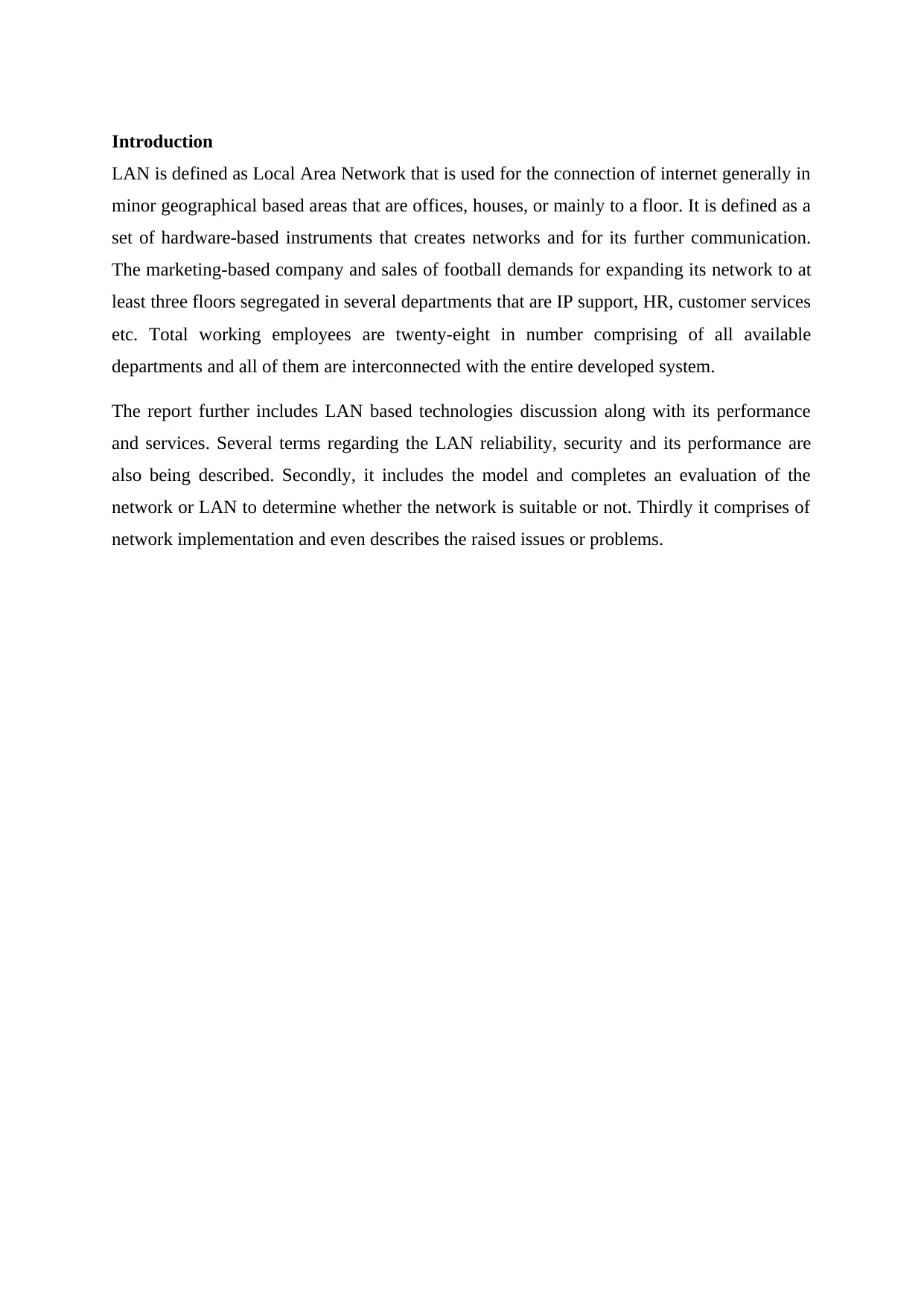
Introduction
LAN is defined as Local Area Network that is used for the connection of internet generally in
minor geographical based areas that are offices, houses, or mainly to a floor. It is defined as a
set of hardware-based instruments that creates networks and for its further communication.
The marketing-based company and sales of football demands for expanding its network to at
least three floors segregated in several departments that are IP support, HR, customer services
etc. Total working employees are twenty-eight in number comprising of all available
departments and all of them are interconnected with the entire developed system.
The report further includes LAN based technologies discussion along with its performance
and services. Several terms regarding the LAN reliability, security and its performance are
also being described. Secondly, it includes the model and completes an evaluation of the
network or LAN to determine whether the network is suitable or not. Thirdly it comprises of
network implementation and even describes the raised issues or problems.
LO1- Understand the impact of LAN technologies
1.1 critically evaluate different LAN technologies
Local Area Network (LAN)
Local area network also called as LAN is a set of networks which can be used in the specified
location for connecting PCs to such a network that shares a common line with the server.
LANs are mainly used in homes, organisations and institutes. The LAN can be of several
types
Wired
Remote or wireless
Combination of the two
The standard LAN that is wired utilises Ethernet so as to entirely associate all the gadgets
together. Remote based or wireless LANs generally utilised the Wi-Fi based network. Some
disadvantages of LAN based networks are that it can only be used in small areas.
LAN and its types
LAN is mainly divided into two possible types that are wired and remote or wireless.
Generally, all private based LANs uses their own router in order to create a system and tackle
with all various associated gadgets. The working of the router includes associating of focal
points and empowerment of the gadgets like Tablets, mobile phones, PCs so that the
communication becomes easier with each other. In the case of LAN, a PC can be converted
into a central point for access and even behaves as a server that provides several machines so
as to access all located files on servers. Also, multiple LAN is combined in order to create a
bigger LAN.
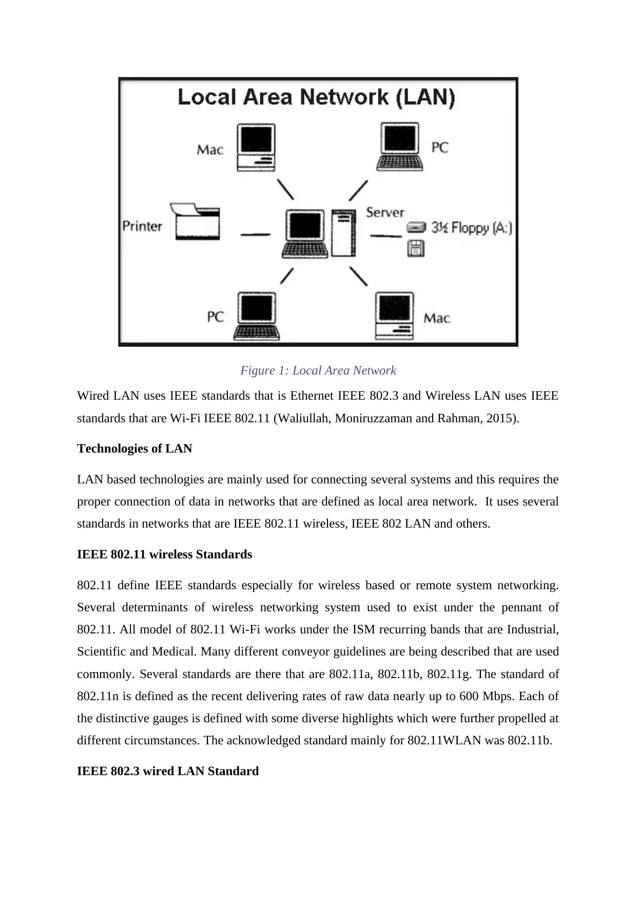
Figure 1: Local Area Network
Wired LAN uses IEEE standards that is Ethernet IEEE 802.3 and Wireless LAN uses IEEE
standards that are Wi-Fi IEEE 802.11 (Waliullah, Moniruzzaman and Rahman, 2015).
Technologies of LAN
LAN based technologies are mainly used for connecting several systems and this requires the
proper connection of data in networks that are defined as local area network. It uses several
standards in networks that are IEEE 802.11 wireless, IEEE 802 LAN and others.
IEEE 802.11 wireless Standards
802.11 define IEEE standards especially for wireless based or remote system networking.
Several determinants of wireless networking system used to exist under the pennant of
802.11. All model of 802.11 Wi-Fi works under the ISM recurring bands that are Industrial,
Scientific and Medical. Many different conveyor guidelines are being described that are used
commonly. Several standards are there that are 802.11a, 802.11b, 802.11g. The standard of
802.11n is defined as the recent delivering rates of raw data nearly up to 600 Mbps. Each of
the distinctive gauges is defined with some diverse highlights which were further propelled at
different circumstances. The acknowledged standard mainly for 802.11WLAN was 802.11b.
IEEE 802.3 wired LAN Standard
Paraphrase This Document
Need a fresh take? Get an instant paraphrase of this document with our AI Paraphraser
IEEE 802.3 comes out to be the widely and mostly used computer networking standards and
means for communication of data. The IEEE here stands for the Institute of Electrical and
Electronics Engineers standards.
The standard of Ethernet is being utilised for higher time and it must be refreshed
consistently in order to meet all requirements of the technology grows. The speed of
information related to communication and Ethernet use to rise consistently and the IEEE
802.3 velocities are being expanded relatively. Ethernet is generally familiar to almost many
because the connection of Ethernet is being utilised in wired PCs that are available. It mainly
provides a backbone to several other frameworks of data based communication that is both
small and substantial (Crow, Widjaja, Kim, and Sakai, 1997).
Virtual LANs, its working, advantages and types
VLAN also defined as Virtual LAN is referred to as logical based sub-network that combines
several devices from various defined local area network. Various physical based networks
support the VLAN that is Ethernet and Wi-Fi.
At the time LAN uses to receive some data from the workstations and it allows the data
labelling with an identifier of VLAN that showcase the VLAN that delivers crucial
information. This entire process is known as Explicit Tagging. It becomes conceivable
sometimes to decide in which VLAN it is easy to place the data for utilizing implicitly related
tagging. In order to determine the data tagging capacity for the utilization of technique, it is
required to keep a bride where the database is regularly refreshed consisting of VLAN
mapping and determines the tagging which is being utilised. Bridges are used with a need to
determine the capacity of the created database and in order to ensure that all scaffolds of
LAN have the similar kind of data in its entire database. After the bridge, used to determine
the flow of information and several LAN related activities the things are properly being
defined. Scaffold determines the information flow and determines the need for the addition of
VLAN identifier to particular information and then it is required to be sent. The event is all
about the transferring of information to the gadgets which plan for the execution of the
VLAN, an identifier of VLAN which is used to add information. If there is a need to operate
a gadget that doesn’t have any learning regarding the usage of VLAN then the information is
sent via bridge without using VLAN identifier.
VLAN Types
VLAN based management
VLAN data
VLAN default
VLAN native
VLAN voice
VLAN Benefits
It helps in enhancement of connections of security and maintaining service based quality
where management of fault is easier and delivers simplified administration especially for a
manager or network admin.
Data communication equipment (DCE) for LAN
This particular equipment for data communication includes repeaters, hubs, bridges, routers
and switches.
Repeater: It gets operated in data, physical and three different network-based layers. It even
doesn’t understand packets, headers and frames.
Switch: It gets operated in network or data layer and also it is defined as point-to-point
device and using several tables of switching to determine the accurate destination.
Router: It gets operated in the layer of the network and gets connected to 2 or more networks
at a same particular time.
Hub: It gets operated in the physical layer and these hubs are further segregated into 2
different types that are active and passive.
Bridge: It gets operated in the layer of the network and performs several functions that are
forwarding, blocking and filtering the frames (Mehdizadeha, Suinggia, Mohammadpoorb,
and Haruna, 2017).
Comparison of interconnecting media of LAN like cables ( STP, Fibre optic, Coaxial, UTP).
1.2 Critically analyse traffic intensive services and their performance.
1) Discuss Voice-over-IP, Video-on-Demand and audio and video streaming, live
streaming and how much network resources they consume such as bandwidth.
Voice-over IP also defined as VO-IP is derived as a technology which permits the making
of calls via an internet-based connection, not just a normal voice call that is analogue. The
IP networks that are being utilised here are WAN or LAN. A technology is introduced
that is Voice-On Demand that allows viewers to pick the type of content they wish to
watch like video or audio for a time that is scheduled. It consumes complete bandwidth
for network resource usage for up to 40 bytes of the IP and 20 bytes of the VOIP.
Streaming is defined as a technique for data transferring which is processed in a
continuous and steady rate making it easier for the user as he doesn’t require to download
a particular file. During the streaming of video or audio, a minute buffer is used to create
that bring an obstacle while downloading and the moment that buffer gets completed
video is again being played. The audio and video that are pre-recorded are being stored on
live streaming or server such as broadcasting and telecasting. It demands bandwidth for
recommended streaming of 2 Mbit/s or more. This type of streaming is even done live in
order to determine standards of streaming. For On-demand based streaming the
bandwidth of 300 Kbit/s is being required and is either made directly available live
streaming and requirements of bandwidth.
2) Discuss Quality-of-Service in LANs and how they can be implemented e.g.
Differentiated Service Code Point, 802.1q frame tagging, IP precedence
The service quality granted in LAN is something crucial as a management system type
that generally manages the network traffic or network services. This type of management
system helps in enhancing the network services. Several components for the network-
based quality services are being described
IP Precedence
It was being used before the Differential Service Code Point (DSCP). The initial three
bits are being used here in order to define a priority and generate high esteem, making the
IP packet more critical. It generally utilises all bit from the field of TOS that are being
found in headers of IP packet enabling three of its bits which generally opposed the
DSCP six bits.
Secure Best Marks with AI Grader
Need help grading? Try our AI Grader for instant feedback on your assignments.

Differentiated Service Code Point
DSCP also defined as Differentiated Service Code Point are being used to describe the
traffic network and along with that manages that traffic network. The Differentiated
Service Code Point delivers the quality in several network services. It mainly is a
complete mechanism that is determined and provides various QoS on IP based modern
network that enables in managing entire traffic overall network (De Pessemier, Stevens,
De Marez, Martens, and Joseph, 2015).
1.3 Discuss LAN concerns and make recommendations to sustain network security,
reliability and performance.
Various types of concerns of LAN along with several recommendations are made in order to
prevent the occurred problems like the security of network, performance and its reliability. It
can be easily accomplished in order to achieve a specific goal which can be made run on
LAN easily, the administrator of the system requires to watch out about the utilization of its
transfer speed. By deliberately monitoring and checking several applications that carry
through high transmission of data, issues like bottlenecks execution which maintains a
tactical distance.
The two key parameters for measurement are Jitter and Latency that benchmarks and
evaluates the network, device and system related performance. The model of network design
a network in a way to make that network highly scalable and even decreases the redundancy.
It highly enhances the management, maintenance and eradicates the entire focus on the
security and performance.
1) Discuss security issues such as confidentiality, integrity and availability (CIA).
The triad of CIA defines the confidentiality, integrity and availability that describe the
model created for policy guild lines regarding the security of data. The Confidentiality
describes the protection of information or data from intruders because of the value it
possesses which is required to keep a secret. The Integrity describes the prevention and
modification of data or information from intruders as well as from several different
unauthorised persons so as to keep the data or information more secure. The Availability
describes the ensuring of data or information that can only be accessed by persons that are
authorised.
2) Explain ways of securing a LAN network e.g. Access Control Lists, VLANs,
Firewalls, etc.
Various ways of network securing are made available that are VLAN usage in order to
separate network from its traffic to enhance the performance. The network is designed in
a way to ensure the security of network that uses several measures that are using of
firewalls in order to protect some extensive networks which are used in different security
ways that are transmitting the outside data and maintaining the extensive configuration
(Pandya, and Patel, 2018).

Paraphrase This Document
Need a fresh take? Get an instant paraphrase of this document with our AI Paraphraser
LO2 Be able to design LAN infrastructures
2.1 design a LAN infrastructure for the company which will facilitate all of their
requirements
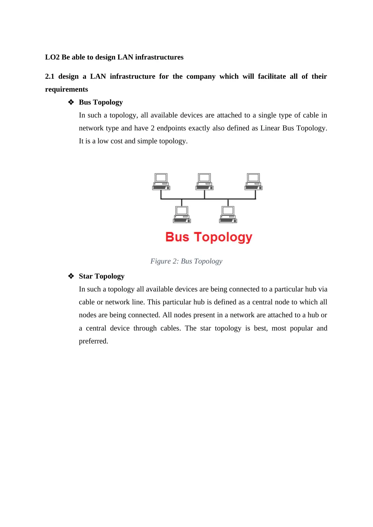
Bus Topology
In such a topology, all available devices are attached to a single type of cable in
network type and have 2 endpoints exactly also defined as Linear Bus Topology.
It is a low cost and simple topology.
Figure 2: Bus Topology
Star Topology
In such a topology all available devices are being connected to a particular hub via
cable or network line. This particular hub is defined as a central node to which all
nodes are being connected. All nodes present in a network are attached to a hub or
a central device through cables. The star topology is best, most popular and
preferred.
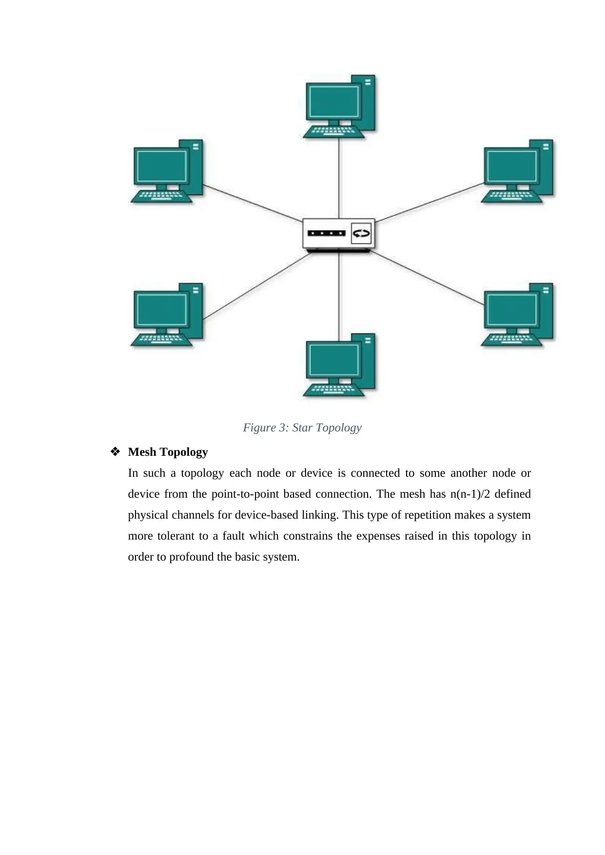
Figure 3: Star Topology
Mesh Topology
In such a topology each node or device is connected to some another node or
device from the point-to-point based connection. The mesh has n(n-1)/2 defined
physical channels for device-based linking. This type of repetition makes a system
more tolerant to a fault which constrains the expenses raised in this topology in
order to profound the basic system.
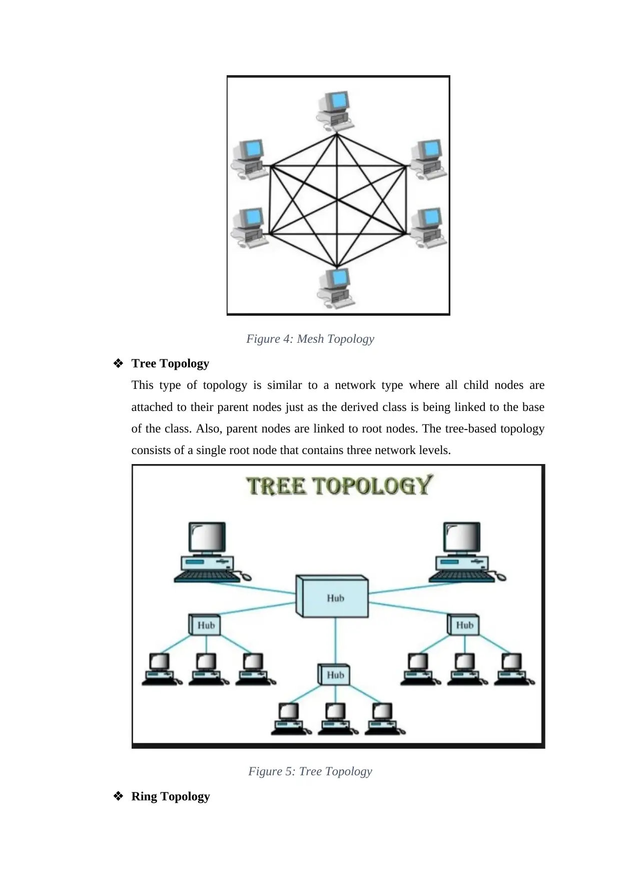
Figure 4: Mesh Topology
Tree Topology
This type of topology is similar to a network type where all child nodes are
attached to their parent nodes just as the derived class is being linked to the base
of the class. Also, parent nodes are linked to root nodes. The tree-based topology
consists of a single root node that contains three network levels.
Figure 5: Tree Topology
Ring Topology
Secure Best Marks with AI Grader
Need help grading? Try our AI Grader for instant feedback on your assignments.
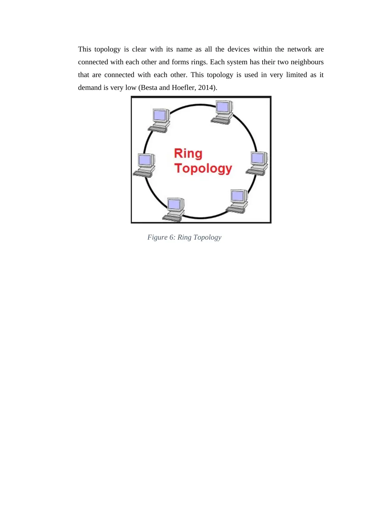
This topology is clear with its name as all the devices within the network are
connected with each other and forms rings. Each system has their two neighbours
that are connected with each other. This topology is used in very limited as it
demand is very low (Besta and Hoefler, 2014).
Figure 6: Ring Topology
connected with each other and forms rings. Each system has their two neighbours
that are connected with each other. This topology is used in very limited as it
demand is very low (Besta and Hoefler, 2014).
Figure 6: Ring Topology
2.2 critically evaluate the suitability of LAN components
There are many types of hardware and software components that are used to develop the
LAN network which is as follows:
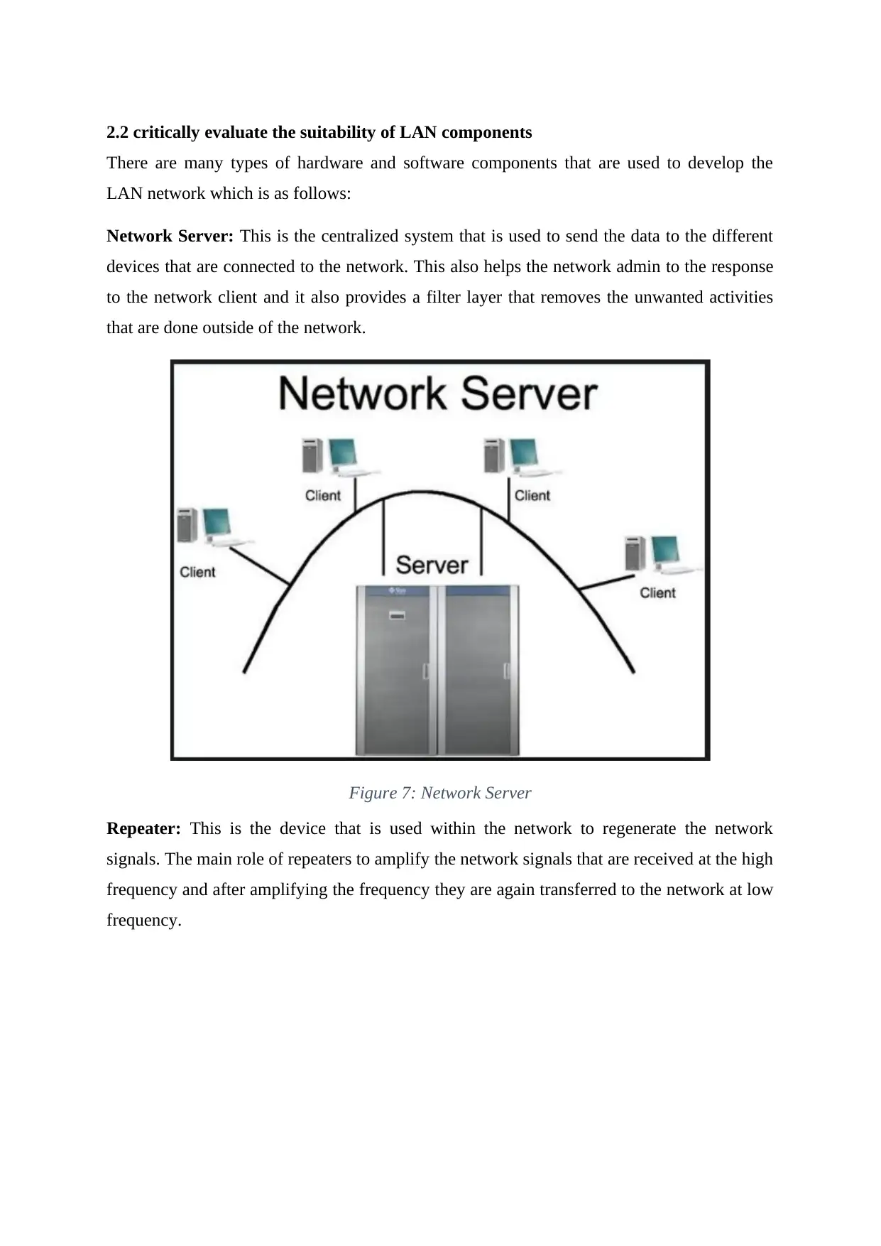
Network Server: This is the centralized system that is used to send the data to the different
devices that are connected to the network. This also helps the network admin to the response
to the network client and it also provides a filter layer that removes the unwanted activities
that are done outside of the network.
Figure 7: Network Server
Repeater: This is the device that is used within the network to regenerate the network
signals. The main role of repeaters to amplify the network signals that are received at the high
frequency and after amplifying the frequency they are again transferred to the network at low
frequency.
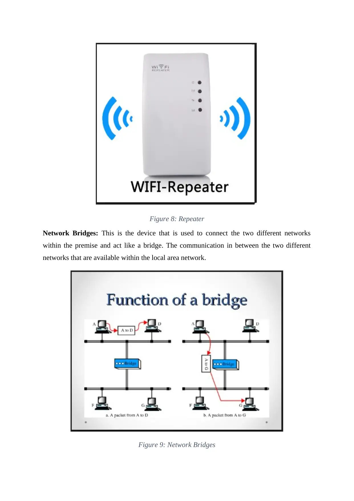
Figure 8: Repeater
Network Bridges: This is the device that is used to connect the two different networks
within the premise and act like a bridge. The communication in between the two different
networks that are available within the local area network.
Figure 9: Network Bridges
Network Bridges: This is the device that is used to connect the two different networks
within the premise and act like a bridge. The communication in between the two different
networks that are available within the local area network.
Figure 9: Network Bridges
Paraphrase This Document
Need a fresh take? Get an instant paraphrase of this document with our AI Paraphraser
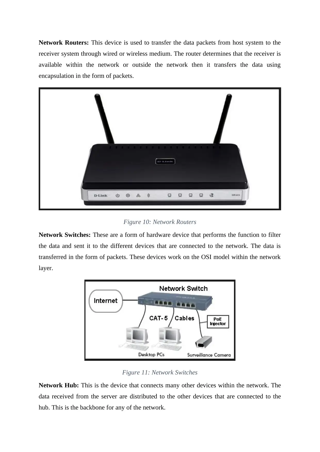
Network Routers: This device is used to transfer the data packets from host system to the
receiver system through wired or wireless medium. The router determines that the receiver is
available within the network or outside the network then it transfers the data using
encapsulation in the form of packets.
Figure 10: Network Routers
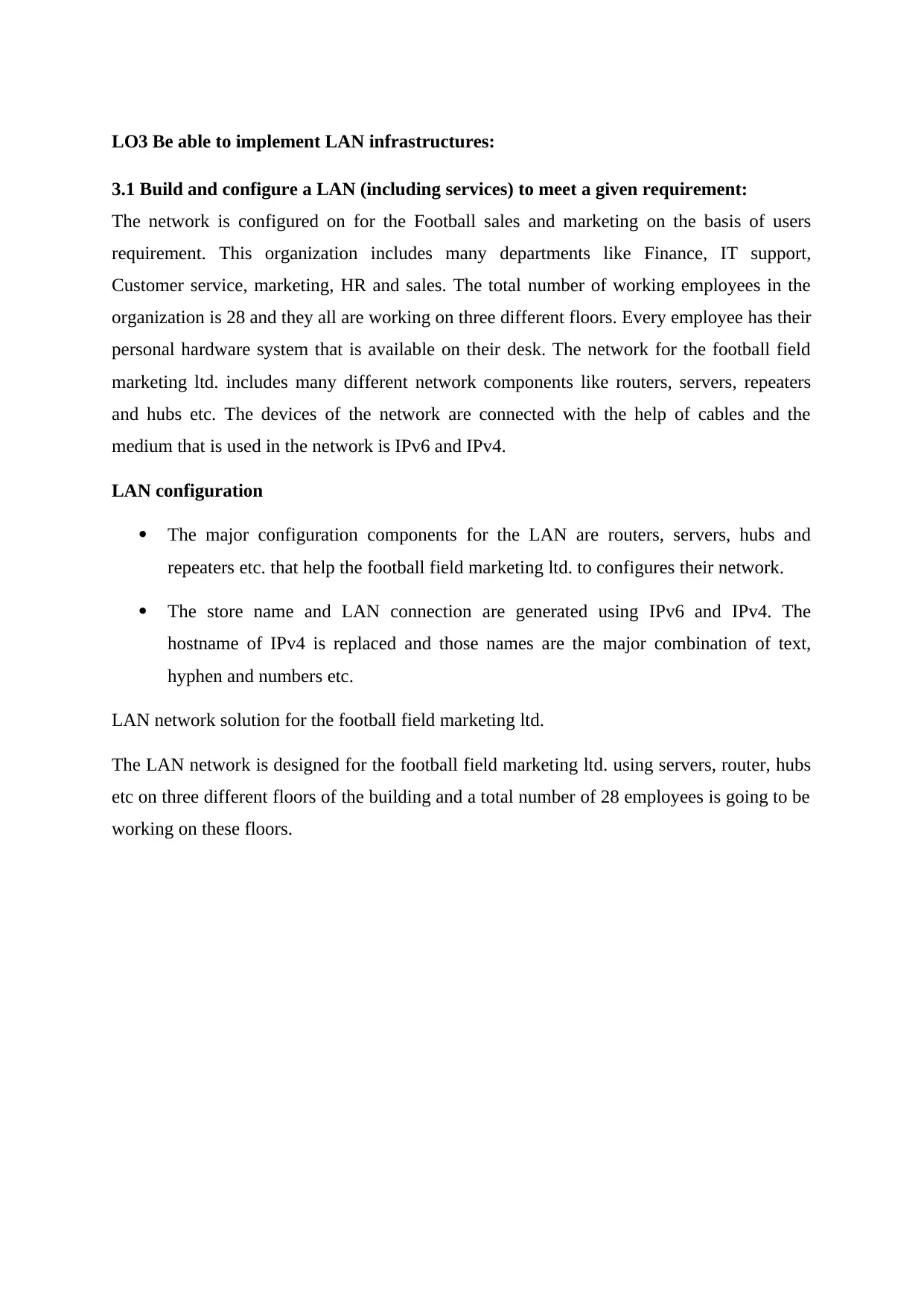
Network Switches: These are a form of hardware device that performs the function to filter
the data and sent it to the different devices that are connected to the network. The data is
transferred in the form of packets. These devices work on the OSI model within the network
layer.
Figure 11: Network Switches
Network Hub: This is the device that connects many other devices within the network. The
data received from the server are distributed to the other devices that are connected to the
hub. This is the backbone for any of the network.
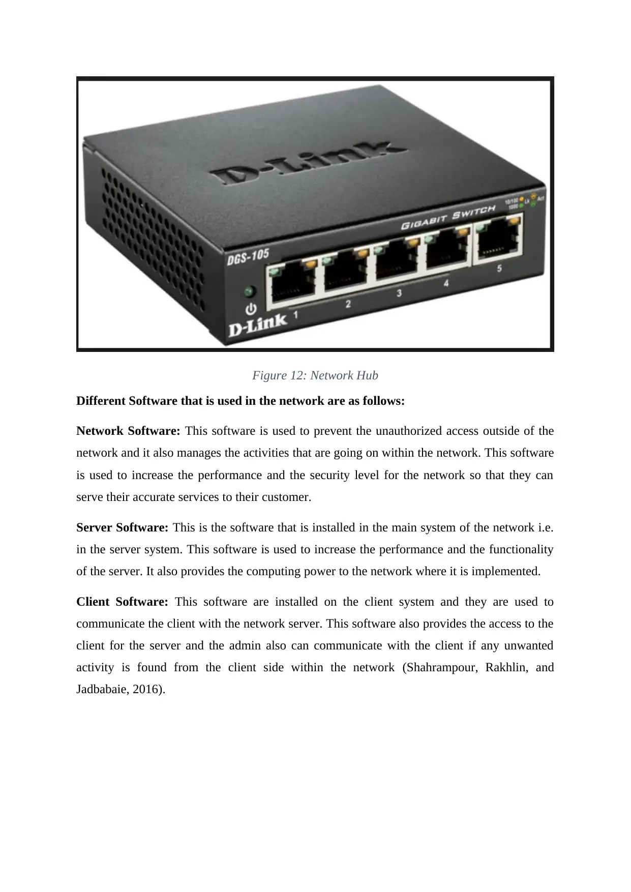
Figure 12: Network Hub
Different Software that is used in the network are as follows:
Network Software: This software is used to prevent the unauthorized access outside of the
network and it also manages the activities that are going on within the network. This software
is used to increase the performance and the security level for the network so that they can
serve their accurate services to their customer.
Server Software: This is the software that is installed in the main system of the network i.e.
in the server system. This software is used to increase the performance and the functionality
of the server. It also provides the computing power to the network where it is implemented.
Client Software: This software are installed on the client system and they are used to
communicate the client with the network server. This software also provides the access to the
client for the server and the admin also can communicate with the client if any unwanted
activity is found from the client side within the network (Shahrampour, Rakhlin, and
Jadbabaie, 2016).
LO3 Be able to implement LAN infrastructures:
3.1 Build and configure a LAN (including services) to meet a given requirement:
The network is configured on for the Football sales and marketing on the basis of users
requirement. This organization includes many departments like Finance, IT support,
Customer service, marketing, HR and sales. The total number of working employees in the
organization is 28 and they all are working on three different floors. Every employee has their
personal hardware system that is available on their desk. The network for the football field
marketing ltd. includes many different network components like routers, servers, repeaters
and hubs etc. The devices of the network are connected with the help of cables and the
medium that is used in the network is IPv6 and IPv4.
LAN configuration
The major configuration components for the LAN are routers, servers, hubs and
repeaters etc. that help the football field marketing ltd. to configures their network.
The store name and LAN connection are generated using IPv6 and IPv4. The
hostname of IPv4 is replaced and those names are the major combination of text,
hyphen and numbers etc.
LAN network solution for the football field marketing ltd.
The LAN network is designed for the football field marketing ltd. using servers, router, hubs
etc on three different floors of the building and a total number of 28 employees is going to be
working on these floors.
Secure Best Marks with AI Grader
Need help grading? Try our AI Grader for instant feedback on your assignments.
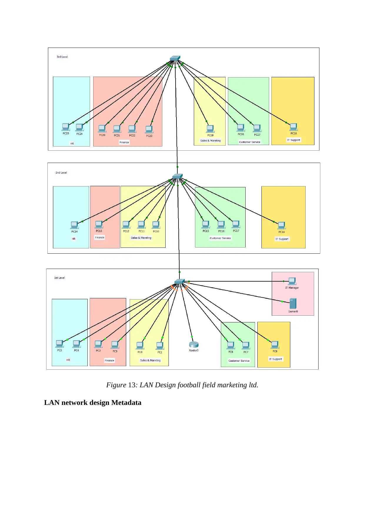
Figure 13: LAN Design football field marketing ltd.
LAN network design Metadata
LAN network design Metadata
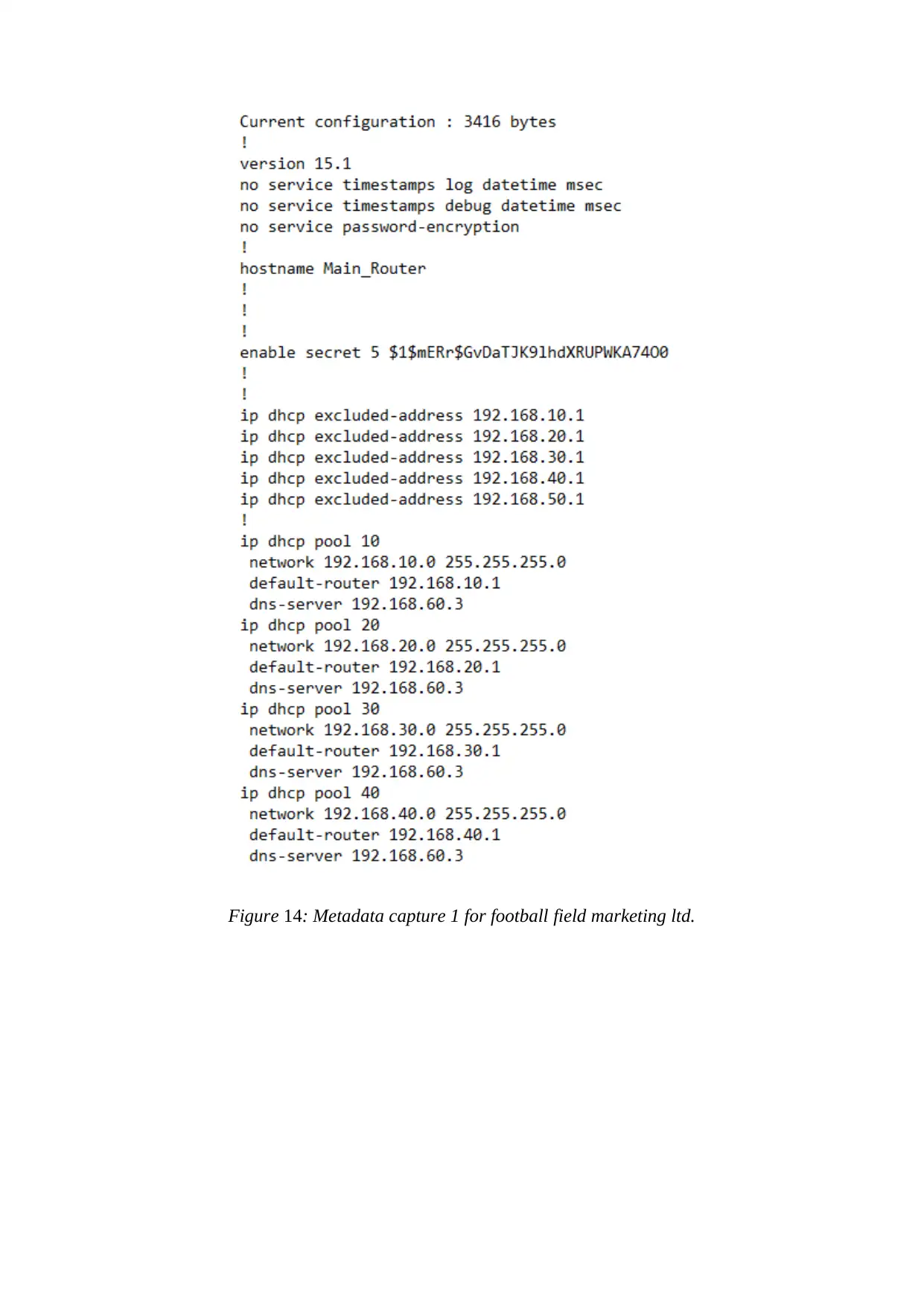
Figure 14: Metadata capture 1 for football field marketing ltd.
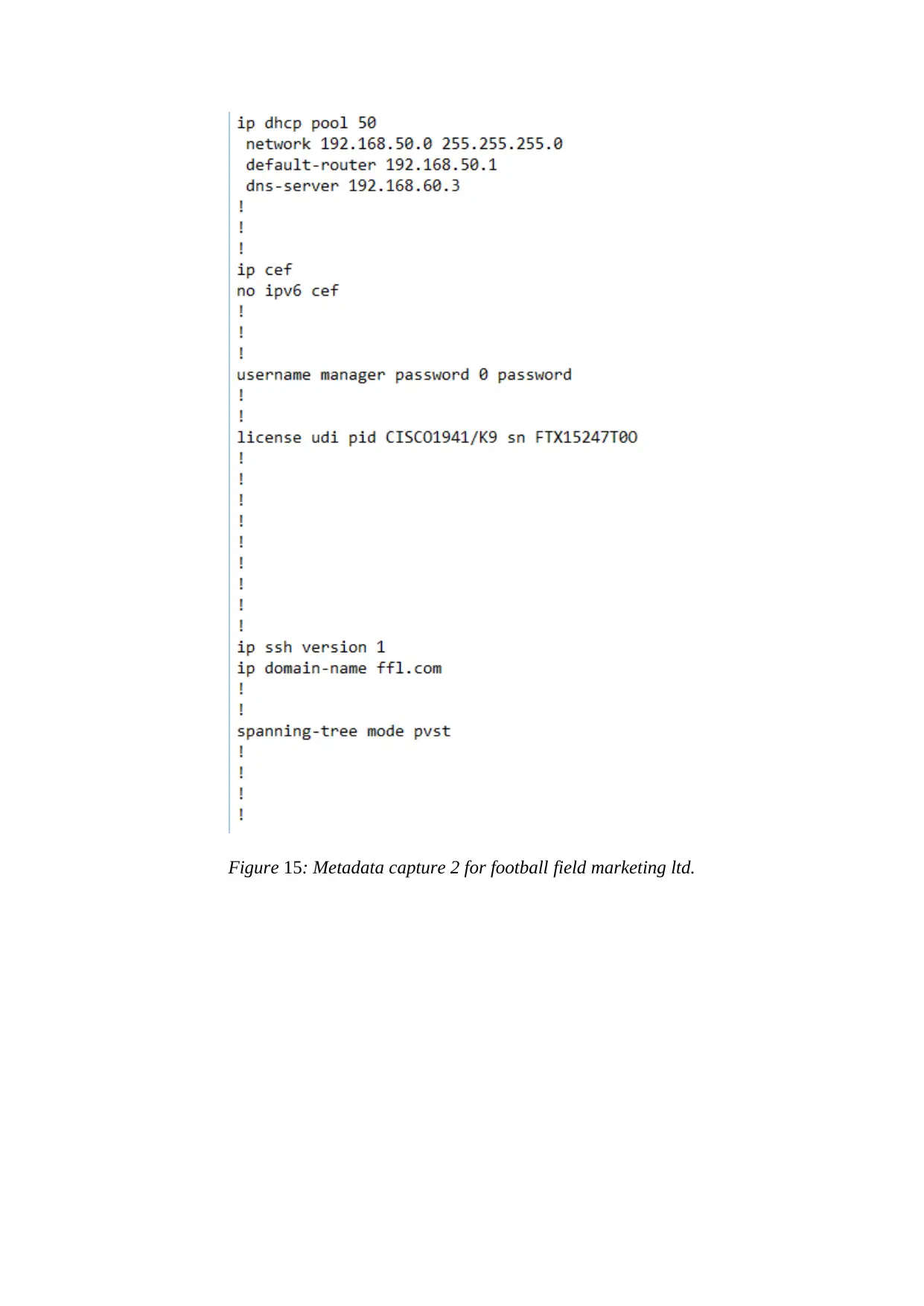
Figure 15: Metadata capture 2 for football field marketing ltd.
Paraphrase This Document
Need a fresh take? Get an instant paraphrase of this document with our AI Paraphraser
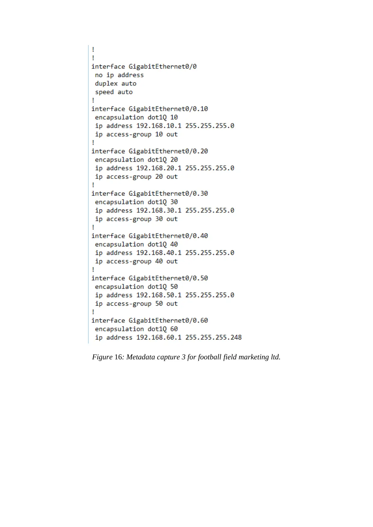
Figure 16: Metadata capture 3 for football field marketing ltd.
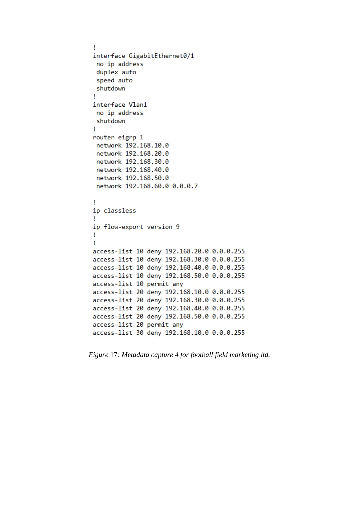
Figure 17: Metadata capture 4 for football field marketing ltd.
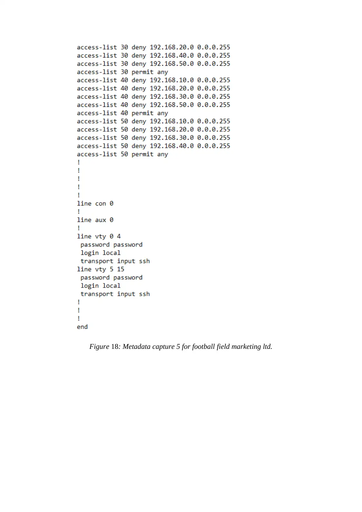
Figure 18: Metadata capture 5 for football field marketing ltd.
Secure Best Marks with AI Grader
Need help grading? Try our AI Grader for instant feedback on your assignments.

HTTP server Domain name for football field marketing ltd.
Figure 19: HTTP server Domain name for football field marketing ltd.
Overall Design for football field marketing ltd (Naik and Oza, 2016).
Figure 19: HTTP server Domain name for football field marketing ltd.
Overall Design for football field marketing ltd (Naik and Oza, 2016).
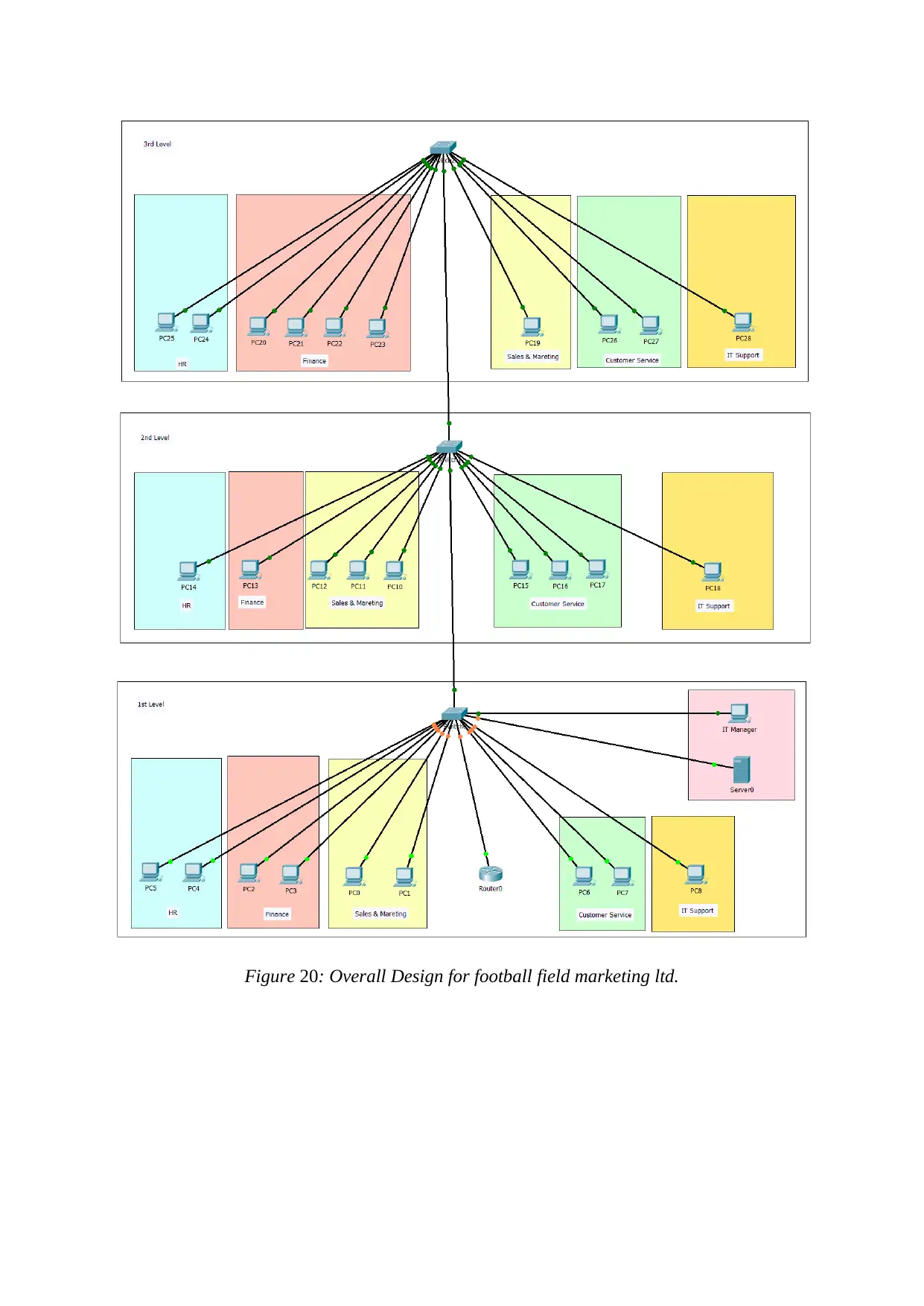
Figure 20: Overall Design for football field marketing ltd.
3.2 Implement network security on a LAN
Security is the measure that maintains the network for the long duration of time. It is very
essentials because it contains unique and very useful data of the customers. The security is
provided in the network by implementing VLAN, firewall, ethernet etc. help football field
marketing ltd. to secure their data. The implementation of VLAN, firewall, Ethernet make the
server very secure and the data cannot be transferred to another network with the help of
packets.
Ethernet Infrastructure
This is the main security feature of any local area network that defines the link layer protocol
by using the TCP/IP. In this process, the data is transferred from one network to another. This
allows the user to enter within the network by using their password and username. The
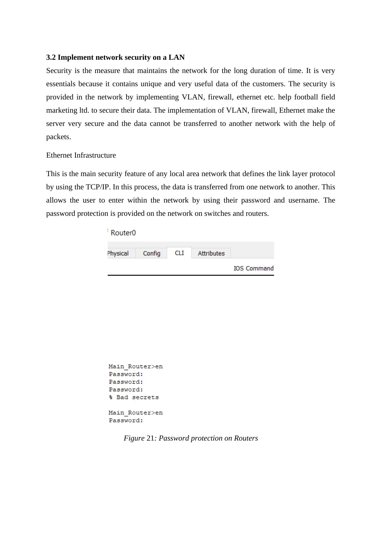
password protection is provided on the network on switches and routers.
Figure 21: Password protection on Routers
Paraphrase This Document
Need a fresh take? Get an instant paraphrase of this document with our AI Paraphraser
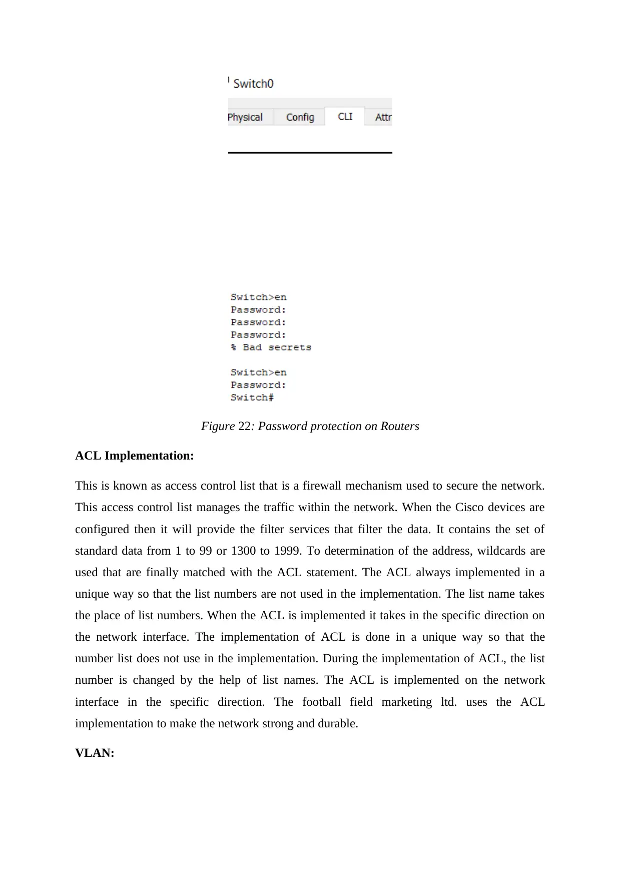
Figure 22: Password protection on Routers
ACL Implementation:
This is known as access control list that is a firewall mechanism used to secure the network.
This access control list manages the traffic within the network. When the Cisco devices are
configured then it will provide the filter services that filter the data. It contains the set of
standard data from 1 to 99 or 1300 to 1999. To determination of the address, wildcards are
used that are finally matched with the ACL statement. The ACL always implemented in a
unique way so that the list numbers are not used in the implementation. The list name takes
the place of list numbers. When the ACL is implemented it takes in the specific direction on
the network interface. The implementation of ACL is done in a unique way so that the
number list does not use in the implementation. During the implementation of ACL, the list
number is changed by the help of list names. The ACL is implemented on the network
interface in the specific direction. The football field marketing ltd. uses the ACL
implementation to make the network strong and durable.
VLAN:
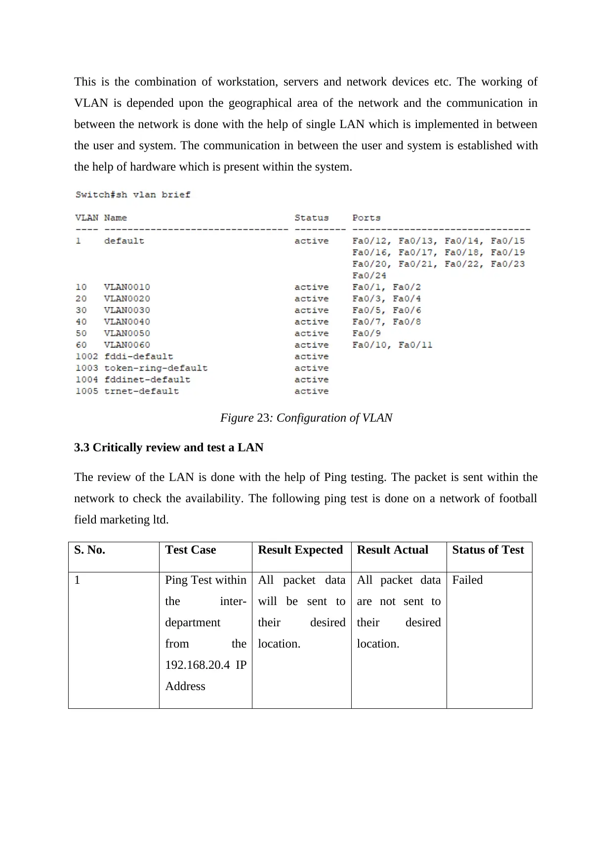
This is the combination of workstation, servers and network devices etc. The working of
VLAN is depended upon the geographical area of the network and the communication in
between the network is done with the help of single LAN which is implemented in between
the user and system. The communication in between the user and system is established with
the help of hardware which is present within the system.
Figure 23: Configuration of VLAN
3.3 Critically review and test a LAN
The review of the LAN is done with the help of Ping testing. The packet is sent within the
network to check the availability. The following ping test is done on a network of football
field marketing ltd.
S. No. Test Case Result Expected Result Actual Status of Test
1 Ping Test within
the inter-
department
from the
192.168.20.4 IP
Address
All packet data
will be sent to
their desired
location.
All packet data
are not sent to
their desired
location.
Failed
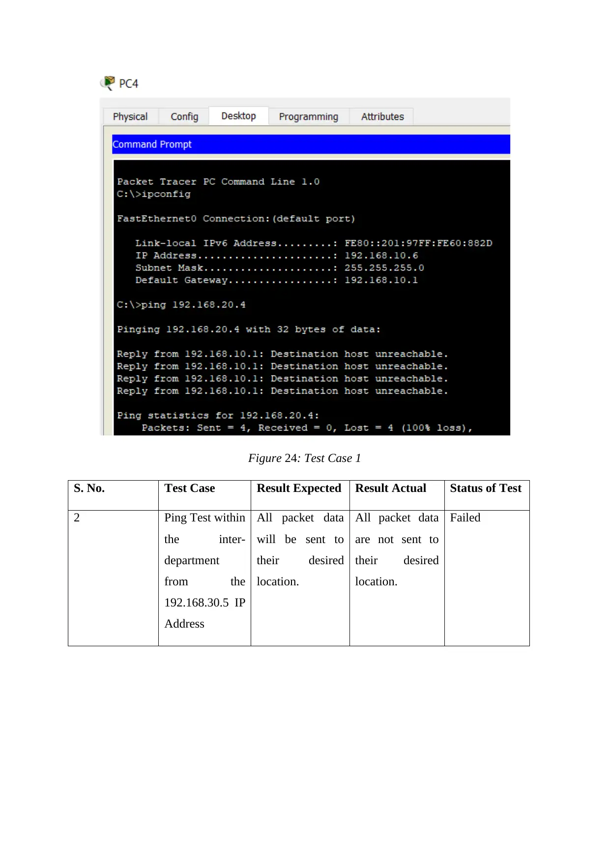
Figure 24: Test Case 1
S. No. Test Case Result Expected Result Actual Status of Test
2 Ping Test within
the inter-
department
from the
192.168.30.5 IP
Address
All packet data
will be sent to
their desired
location.
All packet data
are not sent to
their desired
location.
Failed
S. No. Test Case Result Expected Result Actual Status of Test
2 Ping Test within
the inter-
department
from the
192.168.30.5 IP
Address
All packet data
will be sent to
their desired
location.
All packet data
are not sent to
their desired
location.
Failed
Secure Best Marks with AI Grader
Need help grading? Try our AI Grader for instant feedback on your assignments.
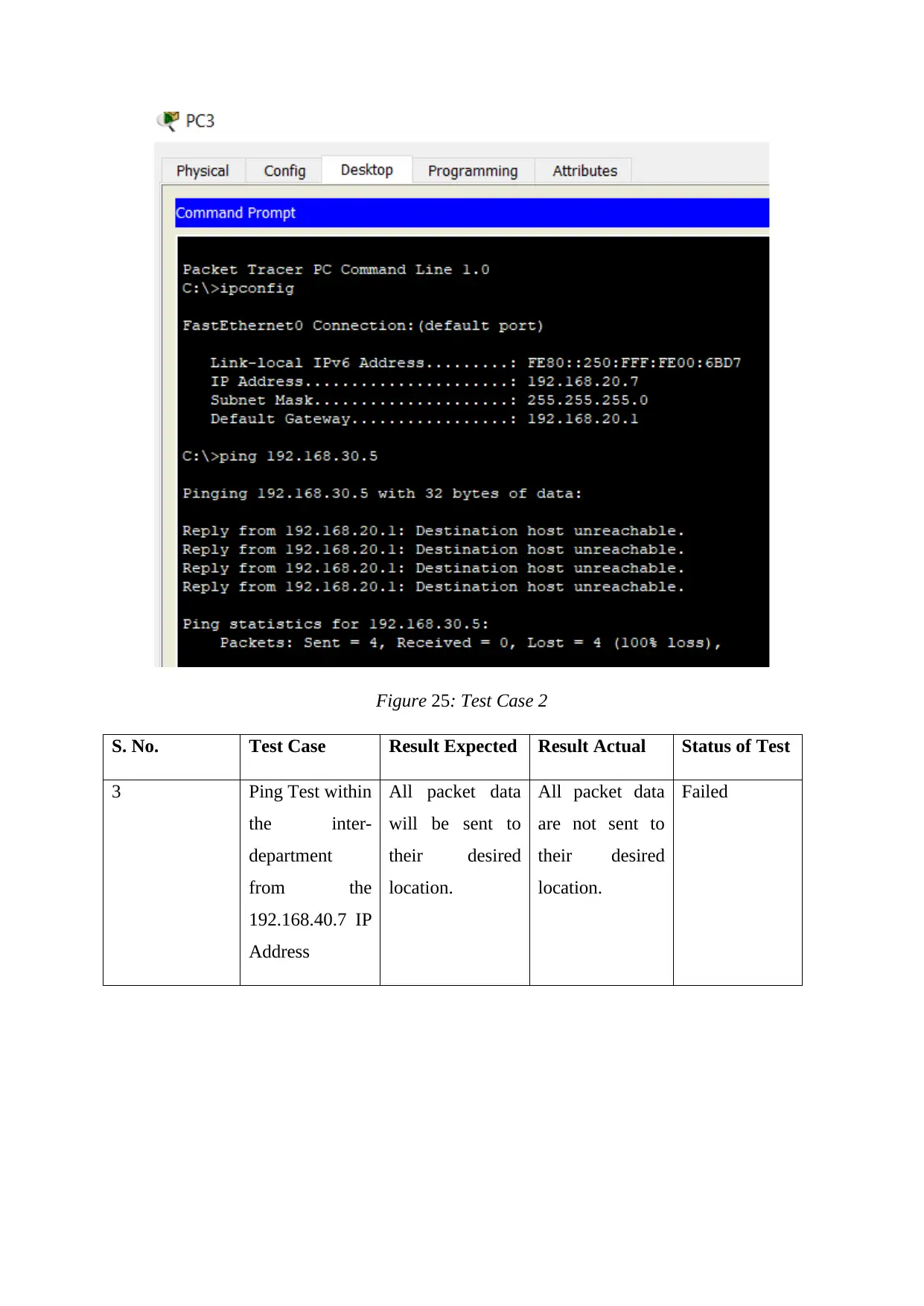
Figure 25: Test Case 2
S. No. Test Case Result Expected Result Actual Status of Test
3 Ping Test within
the inter-
department
from the
192.168.40.7 IP
Address
All packet data
will be sent to
their desired
location.
All packet data
are not sent to
their desired
location.
Failed
S. No. Test Case Result Expected Result Actual Status of Test
3 Ping Test within
the inter-
department
from the
192.168.40.7 IP
Address
All packet data
will be sent to
their desired
location.
All packet data
are not sent to
their desired
location.
Failed
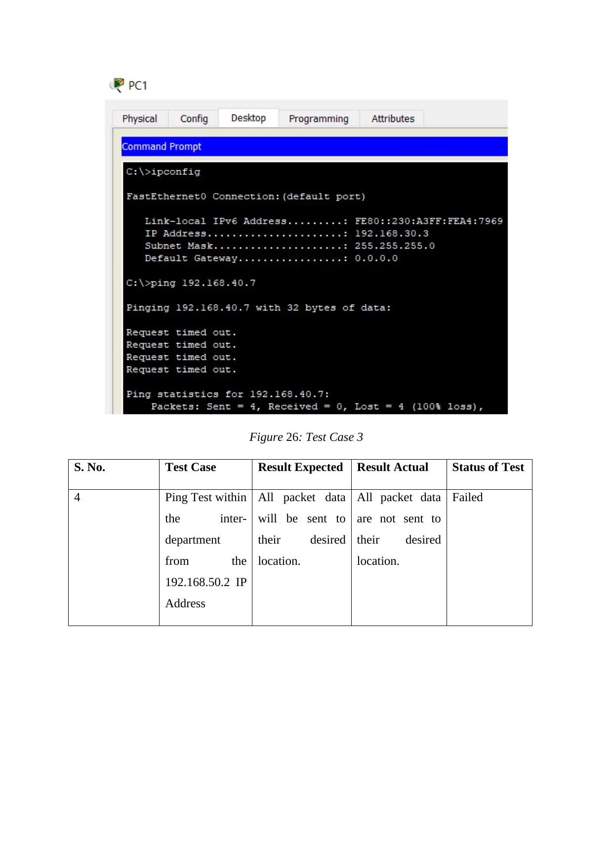
Figure 26: Test Case 3
S. No. Test Case Result Expected Result Actual Status of Test
4 Ping Test within
the inter-
department
from the
192.168.50.2 IP
Address
All packet data
will be sent to
their desired
location.
All packet data
are not sent to
their desired
location.
Failed
S. No. Test Case Result Expected Result Actual Status of Test
4 Ping Test within
the inter-
department
from the
192.168.50.2 IP
Address
All packet data
will be sent to
their desired
location.
All packet data
are not sent to
their desired
location.
Failed
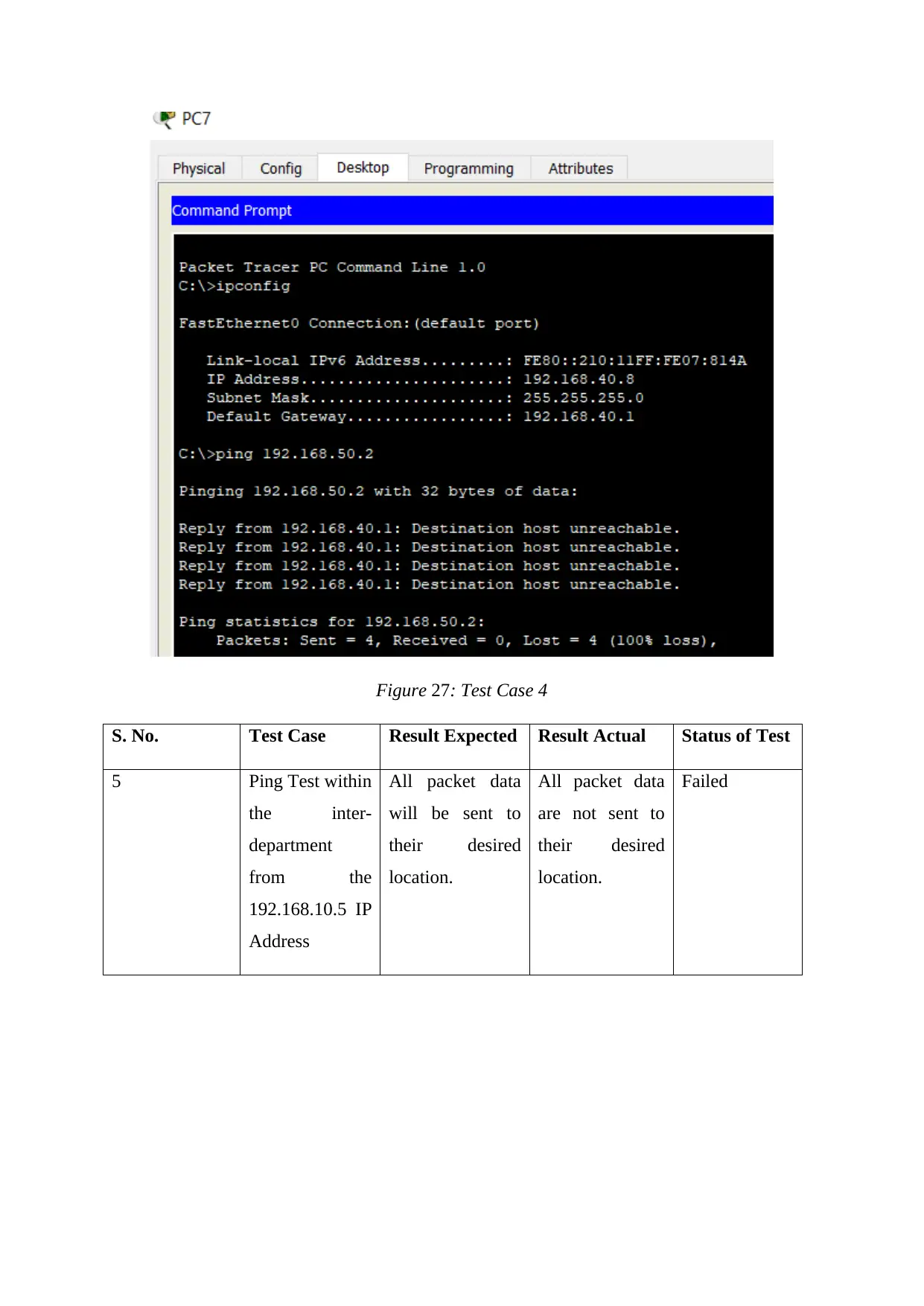
Figure 27: Test Case 4
S. No. Test Case Result Expected Result Actual Status of Test
5 Ping Test within
the inter-
department
from the
192.168.10.5 IP
Address
All packet data
will be sent to
their desired
location.
All packet data
are not sent to
their desired
location.
Failed
S. No. Test Case Result Expected Result Actual Status of Test
5 Ping Test within
the inter-
department
from the
192.168.10.5 IP
Address
All packet data
will be sent to
their desired
location.
All packet data
are not sent to
their desired
location.
Failed
Paraphrase This Document
Need a fresh take? Get an instant paraphrase of this document with our AI Paraphraser
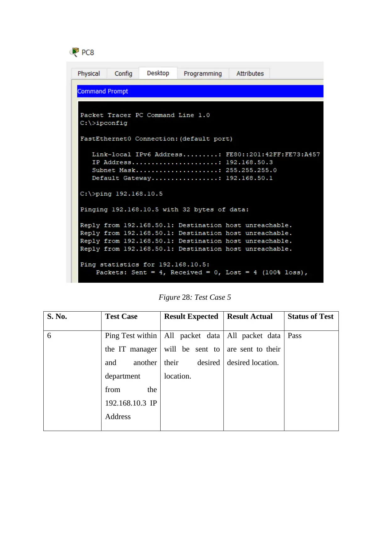
Figure 28: Test Case 5
S. No. Test Case Result Expected Result Actual Status of Test
6 Ping Test within
the IT manager
and another
department
from the
192.168.10.3 IP
Address
All packet data
will be sent to
their desired
location.
All packet data
are sent to their
desired location.
Pass
S. No. Test Case Result Expected Result Actual Status of Test
6 Ping Test within
the IT manager
and another
department
from the
192.168.10.3 IP
Address
All packet data
will be sent to
their desired
location.
All packet data
are sent to their
desired location.
Pass
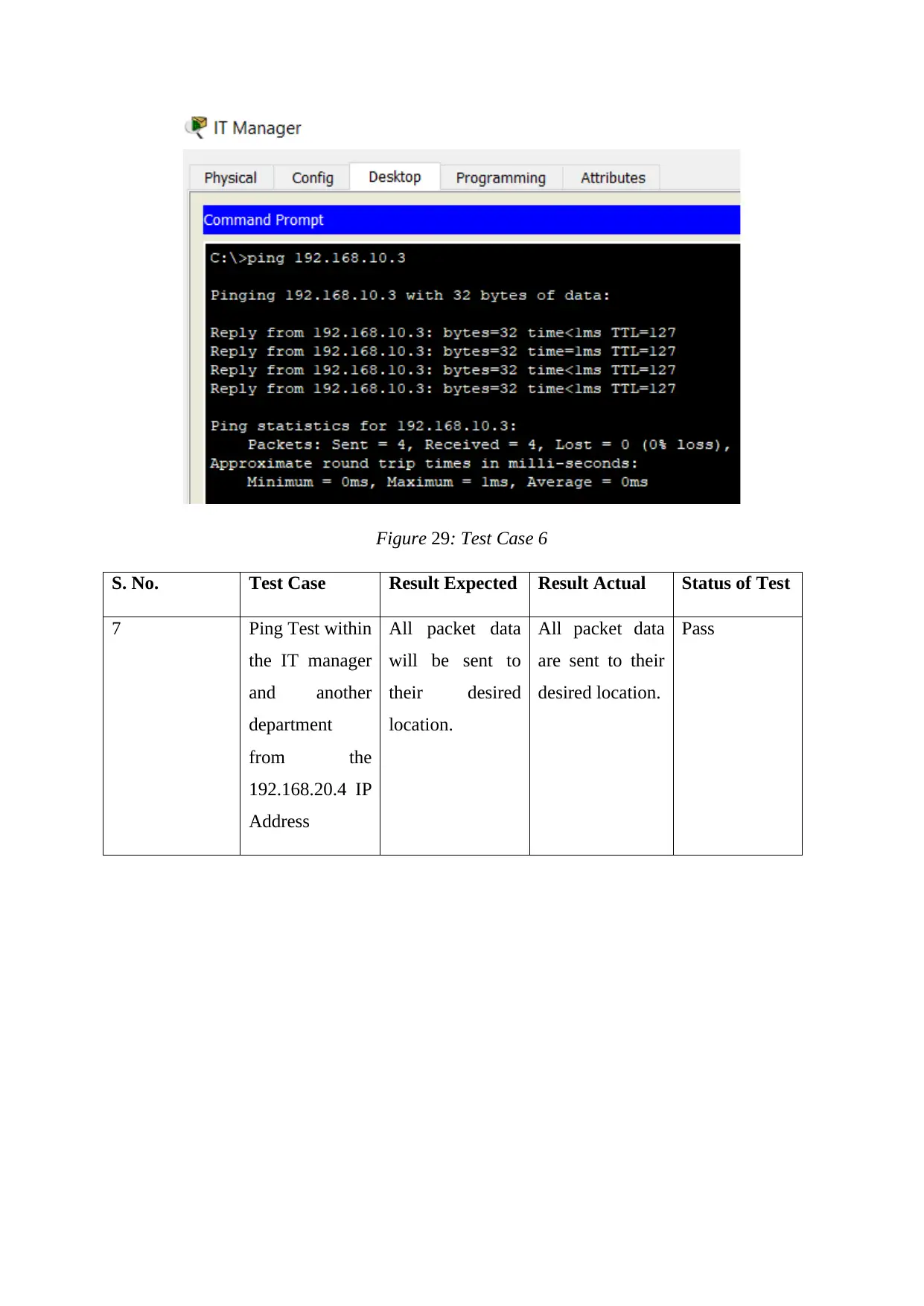
Figure 29: Test Case 6
S. No. Test Case Result Expected Result Actual Status of Test
7 Ping Test within
the IT manager
and another
department
from the
192.168.20.4 IP
Address
All packet data
will be sent to
their desired
location.
All packet data
are sent to their
desired location.
Pass
S. No. Test Case Result Expected Result Actual Status of Test
7 Ping Test within
the IT manager
and another
department
from the
192.168.20.4 IP
Address
All packet data
will be sent to
their desired
location.
All packet data
are sent to their
desired location.
Pass
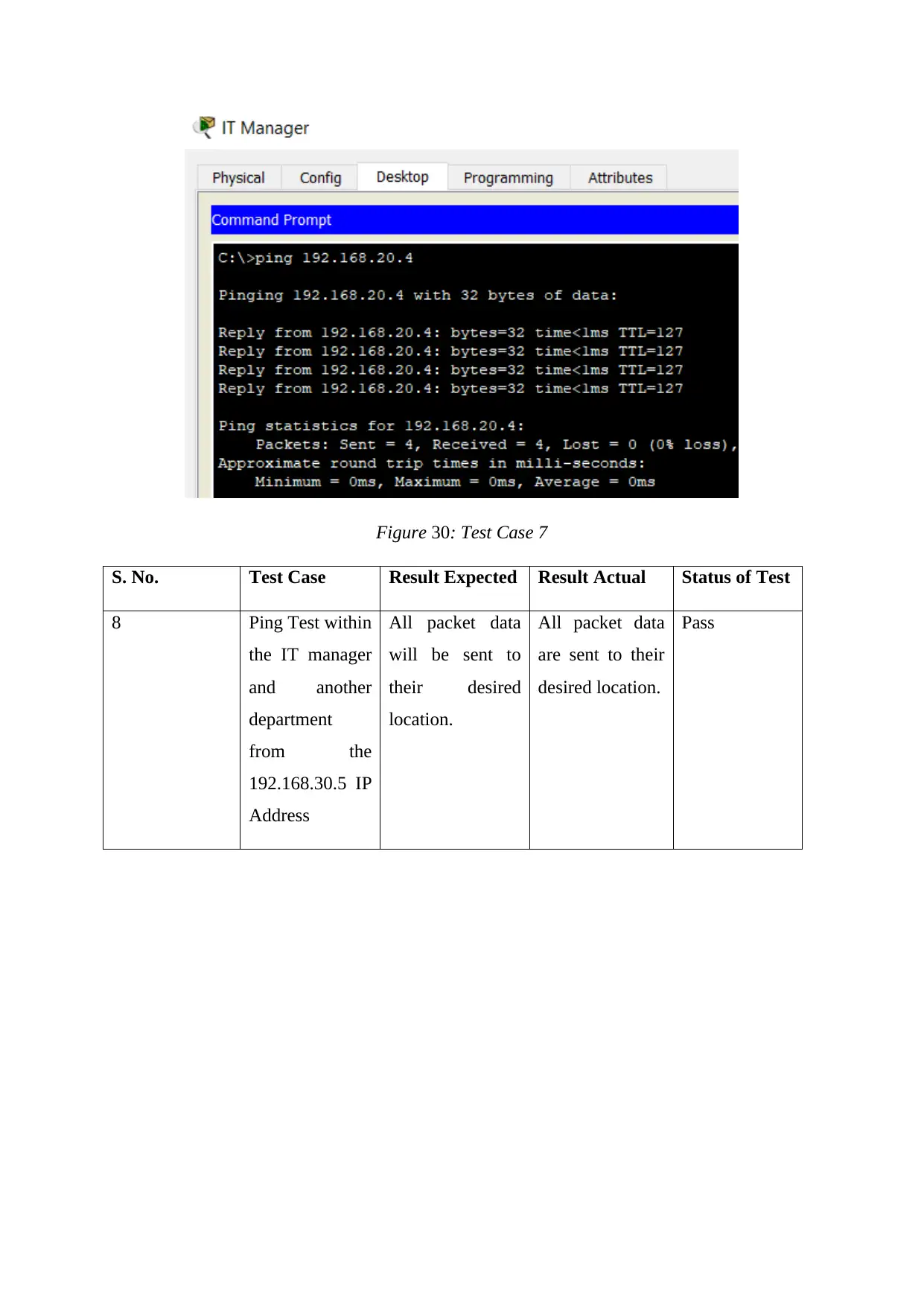
Figure 30: Test Case 7
S. No. Test Case Result Expected Result Actual Status of Test
8 Ping Test within
the IT manager
and another
department
from the
192.168.30.5 IP
Address
All packet data
will be sent to
their desired
location.
All packet data
are sent to their
desired location.
Pass
S. No. Test Case Result Expected Result Actual Status of Test
8 Ping Test within
the IT manager
and another
department
from the
192.168.30.5 IP
Address
All packet data
will be sent to
their desired
location.
All packet data
are sent to their
desired location.
Pass
Secure Best Marks with AI Grader
Need help grading? Try our AI Grader for instant feedback on your assignments.
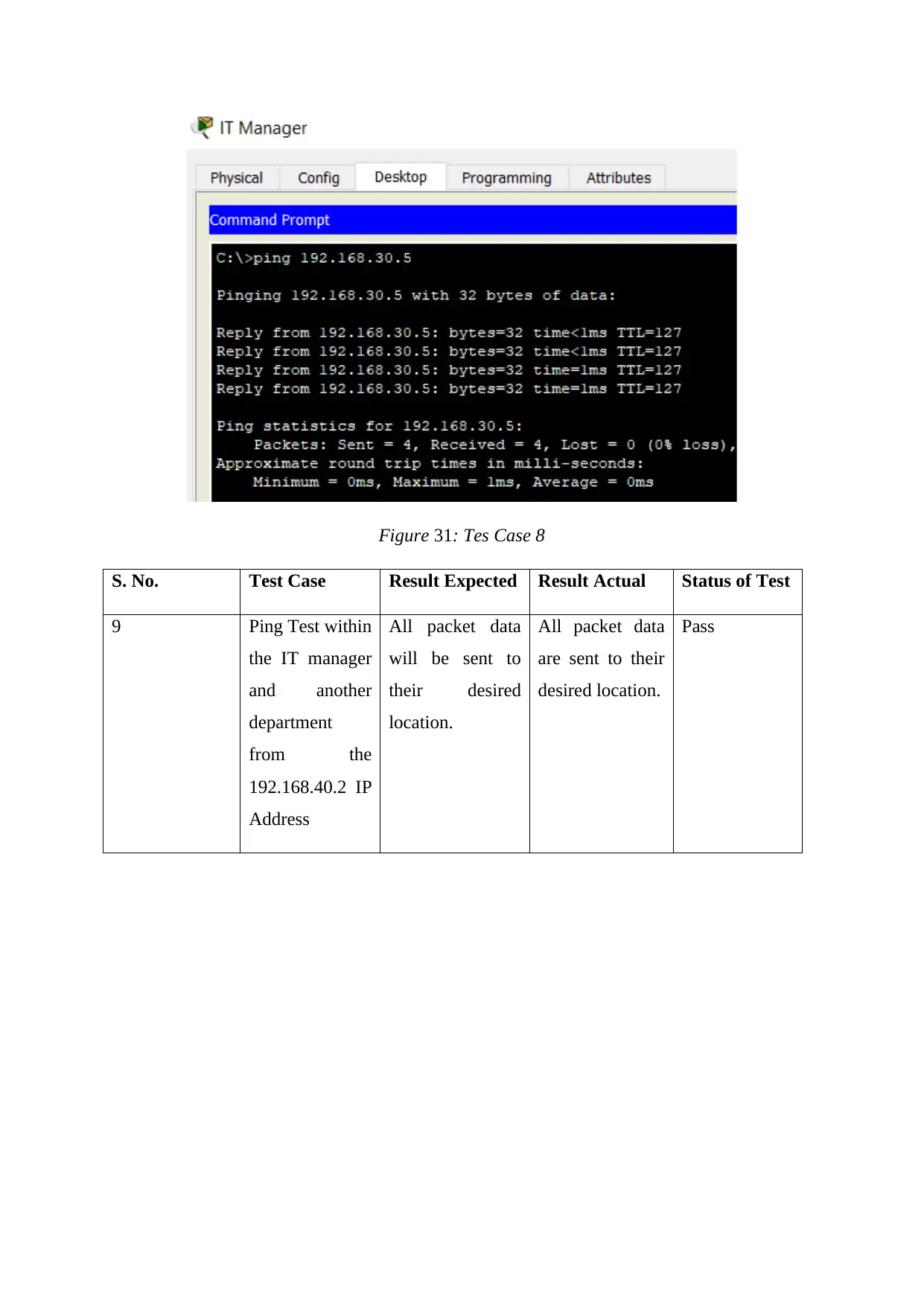
Figure 31: Tes Case 8
S. No. Test Case Result Expected Result Actual Status of Test
9 Ping Test within
the IT manager
and another
department
from the
192.168.40.2 IP
Address
All packet data
will be sent to
their desired
location.
All packet data
are sent to their
desired location.
Pass
S. No. Test Case Result Expected Result Actual Status of Test
9 Ping Test within
the IT manager
and another
department
from the
192.168.40.2 IP
Address
All packet data
will be sent to
their desired
location.
All packet data
are sent to their
desired location.
Pass
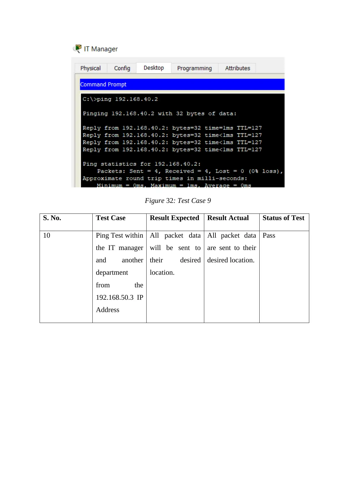
Figure 32: Test Case 9
S. No. Test Case Result Expected Result Actual Status of Test
10 Ping Test within
the IT manager
and another
department
from the
192.168.50.3 IP
Address
All packet data
will be sent to
their desired
location.
All packet data
are sent to their
desired location.
Pass
S. No. Test Case Result Expected Result Actual Status of Test
10 Ping Test within
the IT manager
and another
department
from the
192.168.50.3 IP
Address
All packet data
will be sent to
their desired
location.
All packet data
are sent to their
desired location.
Pass
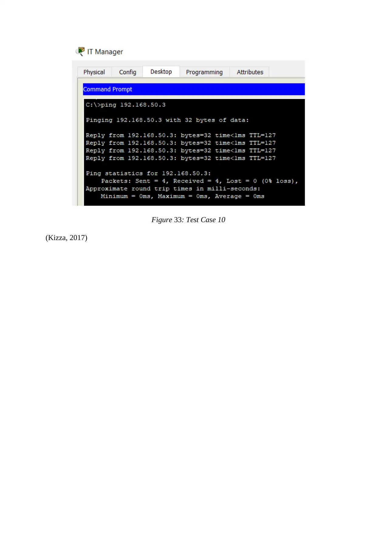
Figure 33: Test Case 10
(Kizza, 2017)
(Kizza, 2017)
Paraphrase This Document
Need a fresh take? Get an instant paraphrase of this document with our AI Paraphraser
LO4 Be able to manage LAN infrastructure:
4.1 Monitor and troubleshoot a LAN
LAN Motoring
Motoring process is used in the LAN design to improve the network process and efficiency.
The network productivity help to increases the motoring of the network, as well as the
network members, also play an important role in the motoring process of the LAN design.
There are so many tools that are available in the market to increase the monitoring process of
the network and some of the tools are as follows:
Microsoft network monitor
Advance IP scanner
Nagios
GIF LanGuard
Footfall filed marketing ltd. used the network motoring process to monitor their network and
some of the advantages of monitor the network are as follows:
Troubleshoot the issue that is available on the network.
Finding the appropriate use and application of Bandwidth.
Deliver the services to the customer with full security.
It is also used to ignore the bottleneck performances.
LAN Network Troubleshooting
The following points will tell us about the LAN network troubleshooting:
The TCP/IP setting should be verified.
The connection of wireless adaptor must be verified.
Ping must be done within the network to verify the network connection.
Working radius must be confirmed.
Network connectivity must be checked.
The setting of the wireless access point and router must be checked.

The connection of the LAN and WAN must be accurate.
There is various command must be used to check the troubleshooting of the network:
Ipconfig: It checks the configuration of IP that can affect the network host.
Paring: This is used to check the connection and advantages in between the tracert and
pint.
Ping: This is used to check the connectivity of the network. The connectivity is
checked with the help of ICMP that checks the connection between the host and
destination.
Tracert: This is used to check the time that is taken to send the packet from host to the
destination system.
4.2 Resolve LAN issues to improve security, reliability and performance
The different methods that are used to improve the issue related to the reliability, security and
performance are as follows:
LAN Reliability:
The router speed is the way to check the reliability of the network. The standard form that is
used to check the speed is MB or GB. The reliability of the network can be easily increased
with the use of packet transmission and TCP/IP. There are some techniques that are also been
used to increase the reliability of the system like orthogonal frequency division.
LAN Security:
The network must be password protected. Service set identifier must be implemented on the
network which includes the change in name of the network or Wi-Fi name. Switch off the
Wi-Fi when the network is not in use. Encryption technique must be used to increase the
security of the network. When IP address is changed then use the wireless router to secure the
network. Remote access must be disabled to secure the network. The software must be up to
date so that the bugs can be removed to secure the server of the network.
LAN Performance:
The network must use the WLAN and VLAN connection so that more connection will be
established in the network. The performance of the network will be increased by the use of
AV control and TCP/IP. The protocol acceleration will help the network to increase the
performance of the network. The performance can be increased by implementation of the
QOS (quality of services) and packet shaping.
Secure Best Marks with AI Grader
Need help grading? Try our AI Grader for instant feedback on your assignments.
4.3 Critically evaluate the performance of a LAN
The performance of the network must be evaluated with the help of testing and it also
determined with the help of troubleshooting and monitoring of the system. The network
performance can be affected by cables, connection, deployment security protocols etc. Some
of the other terms that are used to increase the performance of the network that is as follows:
Inspection of the hardware components that are used in the network within the cycle
of time.
Data must be on backup if in case of any damage to the network the data can be
recovered easily.
Router issue checking plays an important role in the network deployment.
The proper configuration must be implemented properly so that the software and
hardware can easily deploy easily.
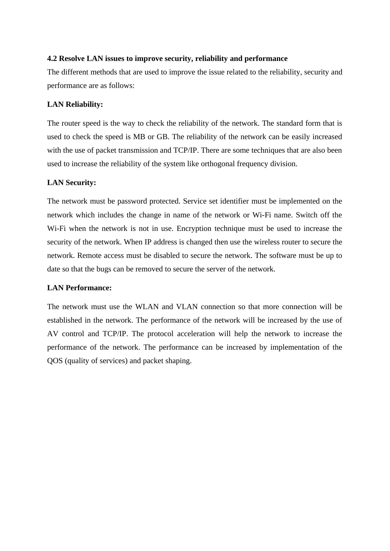
Figure 34: Ping Test 1
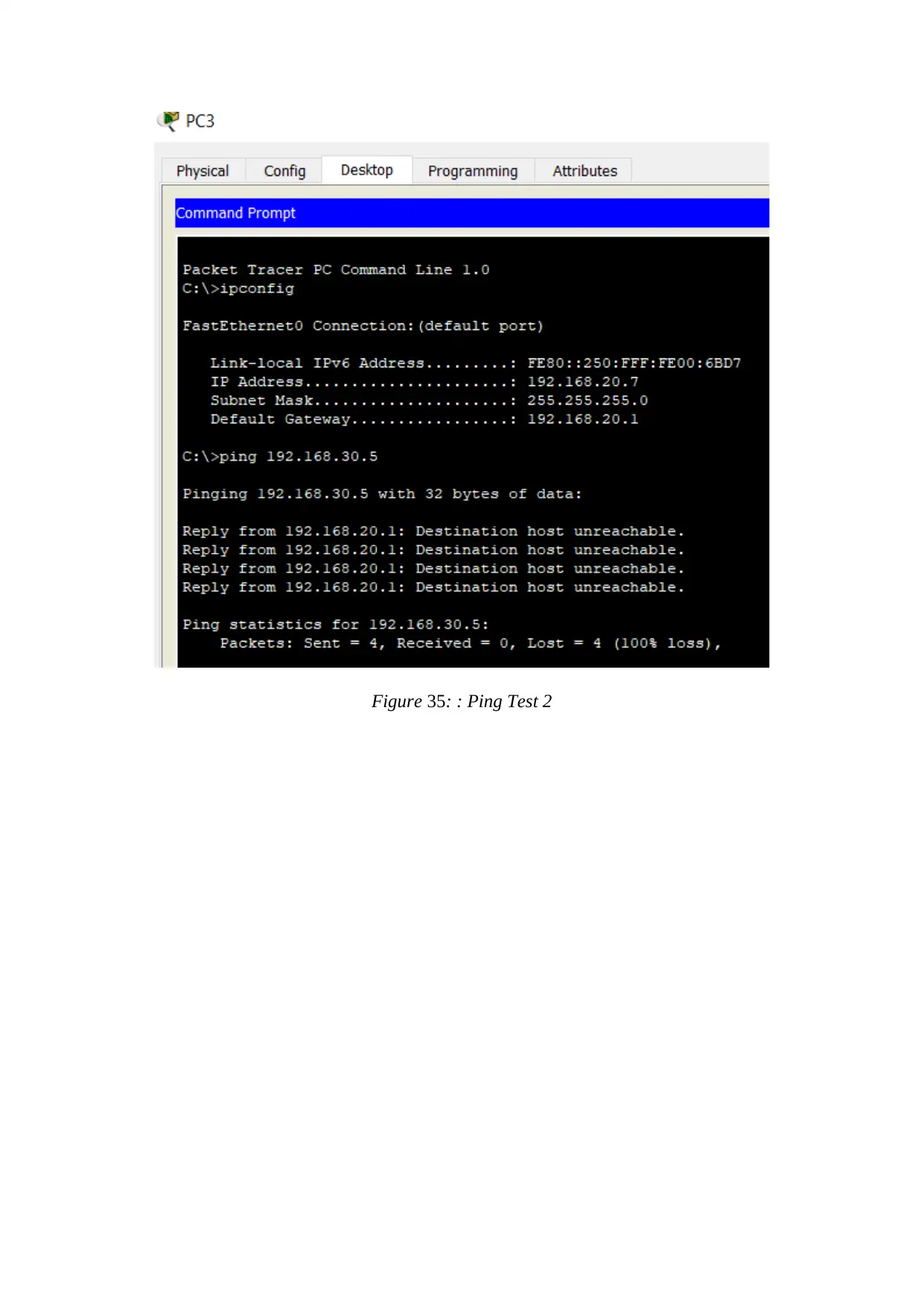
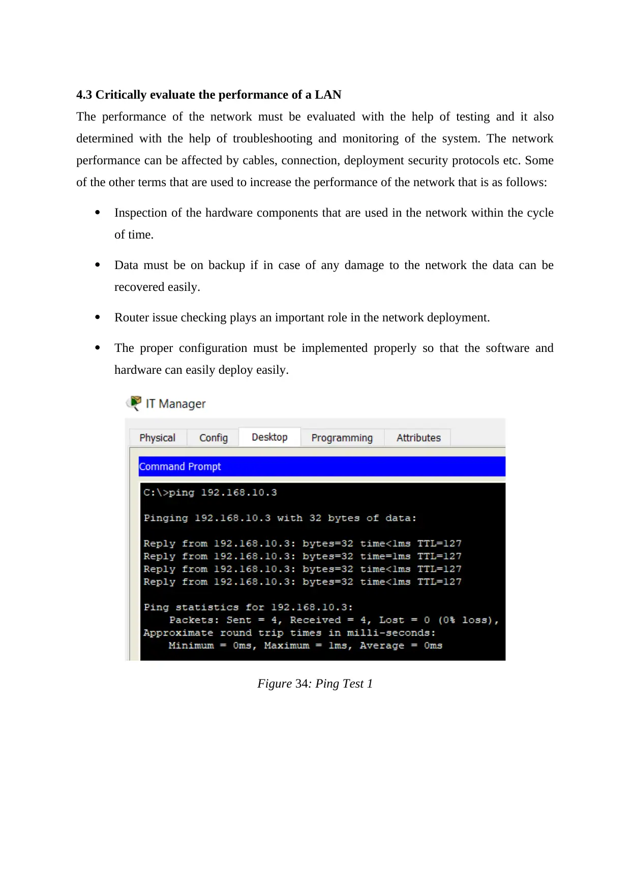
Figure 35: : Ping Test 2
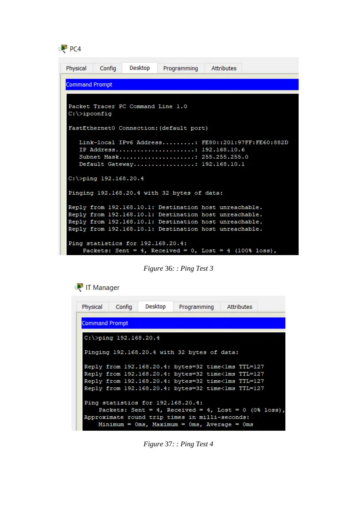
Figure 36: : Ping Test 3
Figure 37: : Ping Test 4
Figure 37: : Ping Test 4
Paraphrase This Document
Need a fresh take? Get an instant paraphrase of this document with our AI Paraphraser
The above images show the loss that is done during the sending the packet from the host
system to destination system. In all above images, 4 packets are sent to the destination system
with 0 to 100% loss of Packet.
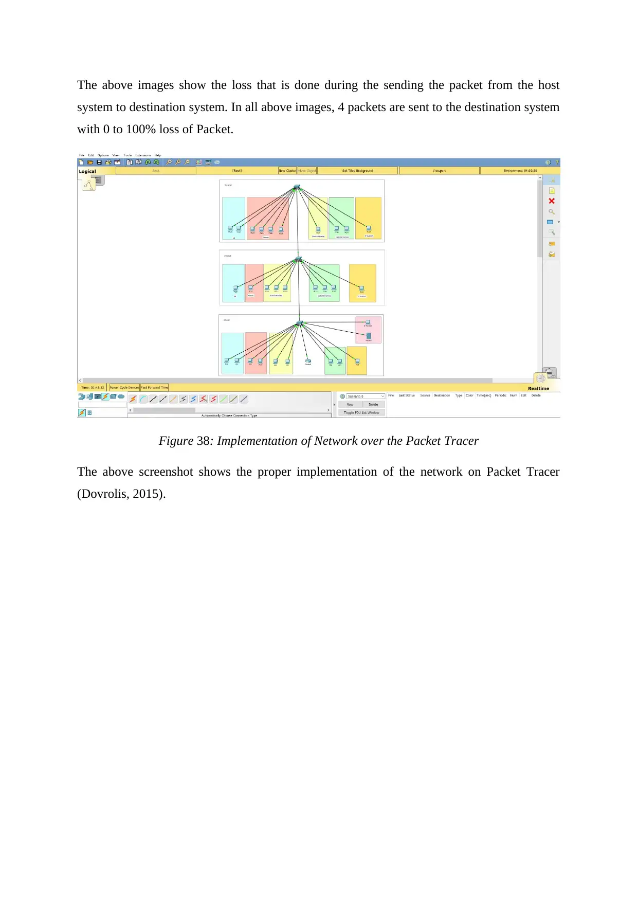
Figure 38: Implementation of Network over the Packet Tracer
The above screenshot shows the proper implementation of the network on Packet Tracer
(Dovrolis, 2015).
system to destination system. In all above images, 4 packets are sent to the destination system
with 0 to 100% loss of Packet.
Figure 38: Implementation of Network over the Packet Tracer
The above screenshot shows the proper implementation of the network on Packet Tracer
(Dovrolis, 2015).
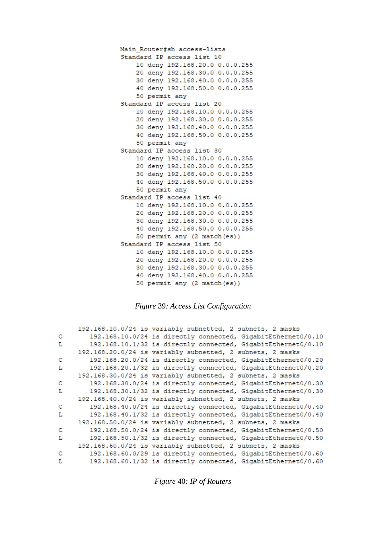
Figure 39: Access List Configuration
Figure 40: IP of Routers
Figure 40: IP of Routers
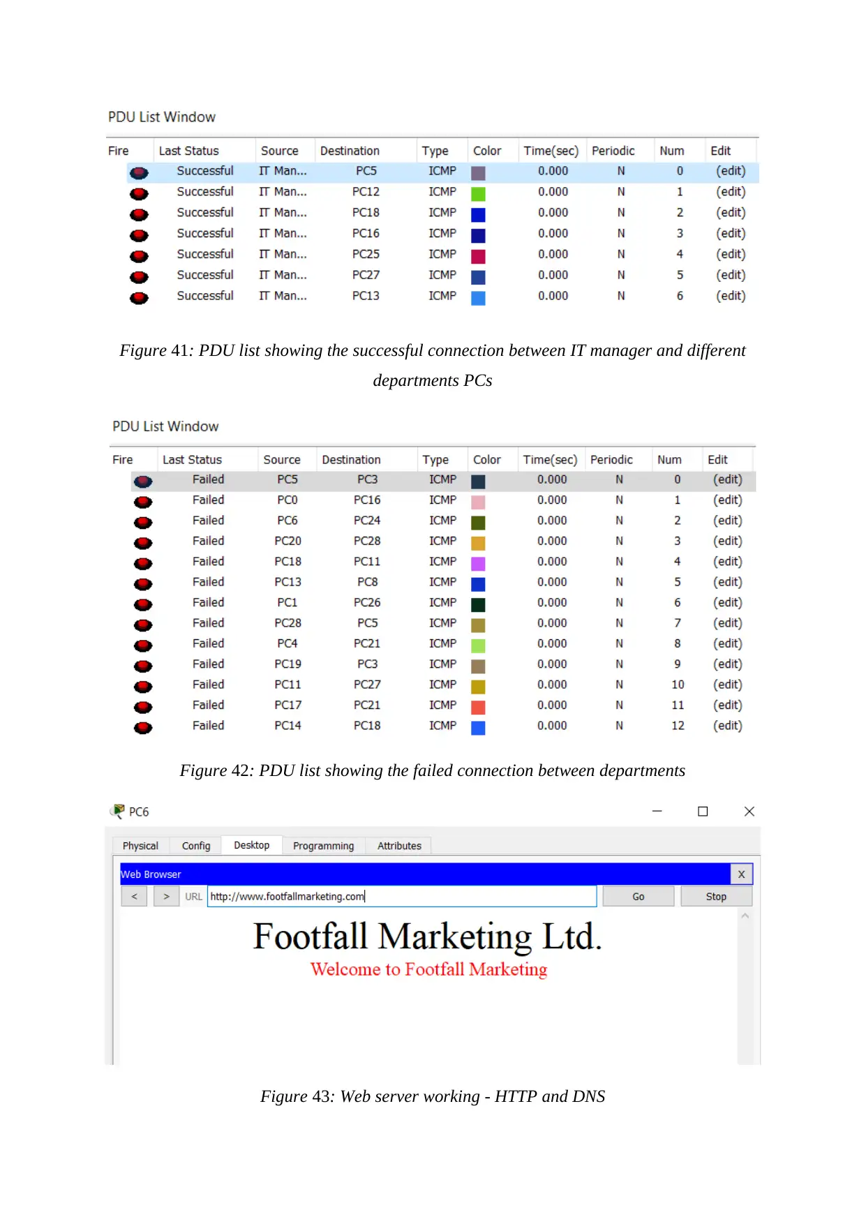
Figure 41: PDU list showing the successful connection between IT manager and different
departments PCs
Figure 42: PDU list showing the failed connection between departments
Figure 43: Web server working - HTTP and DNS
departments PCs
Figure 42: PDU list showing the failed connection between departments
Figure 43: Web server working - HTTP and DNS
Secure Best Marks with AI Grader
Need help grading? Try our AI Grader for instant feedback on your assignments.

Conclusion
I have successfully implemented the complete network of the sales of Football and its
marketing organisation especially for all its departments using its network-based devices. The
report consists of networking based issues along with its solution. Several recommendations
related to security are also being implemented in the entire report. The test plans and reviews
are being included in this described report.
Reference
Waliullah, M., Moniruzzaman, A.B.M. and Rahman, M.S., 2015. An Experimental Study
Analysis of Security Attacks at IEEE 802. 11 Wireless Local Area Network. International
Journal of Future Generation Communication and Networking, 8(1), pp.9-18.
Crow, B.P., Widjaja, I., Kim, J.G. and Sakai, P.T., 1997. IEEE 802.11 wireless local area
networks. IEEE Communications magazine, 35(9), pp.116-126.
Mehdizadeha, A., Suinggia, K., Mohammadpoorb, M. and Haruna, H., 2017, December.
Virtual Local Area Network (VLAN): Segmentation and Security. In The Third International
Conference on Computing Technology and Information Management (ICCTIM2017) (p. 78).
De Pessemier, T., Stevens, I., De Marez, L., Martens, L. and Joseph, W., 2015. Analysis of
the quality of experience of a commercial voice-over-IP service. Multimedia Tools and
Applications, 74(15), pp.5873-5895.
Pandya, D.C. and Patel, N.J., 2018. TO STUDY AND ANALYZE THE IMPACT OF
CONFIDENTIALITY, INTEGRITY, AND AVAILABILITY (CIA) ON COMMON
VULNERABILITY SCORING SYSTEM (CVSS) BASE SCORE. International Journal of
Advanced Research in Computer Science, 9(1), pp.883-886.
Besta, M. and Hoefler, T., 2014, November. Slim fly: A cost effective low-diameter network
topology. In Proceedings of the International Conference for High Performance Computing,
Networking, Storage and Analysis (pp. 348-359). IEEE Press.
Shahrampour, S., Rakhlin, A. and Jadbabaie, A., 2016. Distributed detection: Finite-time
analysis and impact of network topology. IEEE Transactions on Automatic Control, 61(11),
pp.3256-3268.
Naik, P.G. and Oza, K.S., 2016. Implementation of Fuzzy Text Parser for Querying LAN
Configuration Information.
Kizza, J.M., 2017. Guide to computer network security. Spri
Dovrolis, C., 2015, March. Enabling Wireless LAN Troubleshooting. In Passive and Active
Measurement: 16th International Conference, PAM 2015, New York, NY, USA, March 19-20,
2015, Proceedings (Vol. 8995, p. 318). Springer.

1 out of 55
Related Documents
Your All-in-One AI-Powered Toolkit for Academic Success.
+13062052269
info@desklib.com
Available 24*7 on WhatsApp / Email
![[object Object]](/_next/static/media/star-bottom.7253800d.svg)
Unlock your academic potential
© 2024 | Zucol Services PVT LTD | All rights reserved.


