logo

Machine Circuit Design Assignment Project


Added on  2022-08-22

5 Pages963 Words26 Views
 | 
 | 
 | 
Course Title
Project Name
Student Name: Manikarnika Rajoriya
Student ID: s5197037
Machine Circuit Design Assignment Project_1

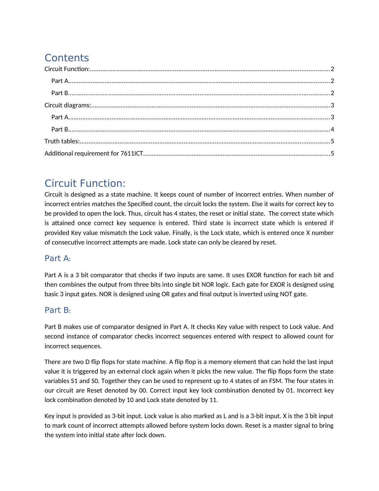
Contents
Circuit Function:......................................................................................................... 2
Part A...................................................................................................................... 2
Part B...................................................................................................................... 2
Circuit diagrams:........................................................................................................ 3
Part A...................................................................................................................... 3
Part B...................................................................................................................... 4
Truth tables:............................................................................................................... 5
Additional requirement for 7611ICT........................................................................... 5
Circuit Function:
Circuit is designed as a state machine. It keeps count of number of incorrect entries.
When number of incorrect entries matches the Specified count, the circuit locks the
system. Else it waits for correct key to be provided to open the lock. Thus, circuit
has 4 states, the reset or initial state. The correct state which is attained once
correct key sequence is entered. Third state is incorrect state which is entered if
provided Key value mismatch the Lock value. Finally, is the Lock state, which is
entered once X number of consecutive incorrect attempts are made. Lock state can
only be cleared by reset.
Part A:
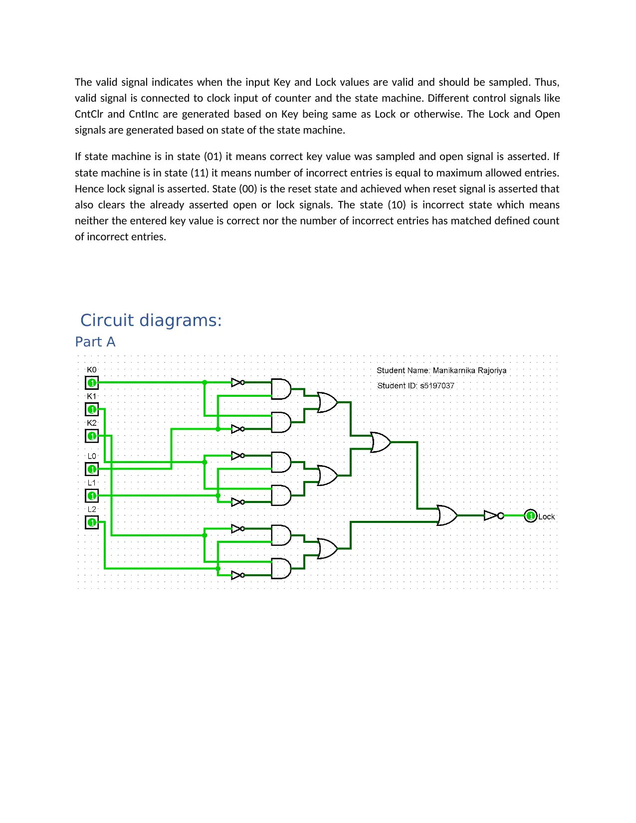
Part A is a 3 bit comparator that checks if two inputs are same. It uses EXOR
function for each bit and then combines the output from three bits into single bit
NOR logic. Each gate for EXOR is designed using basic 3 input gates. NOR is
designed using OR gates and final output is inverted using NOT gate.
Part B:
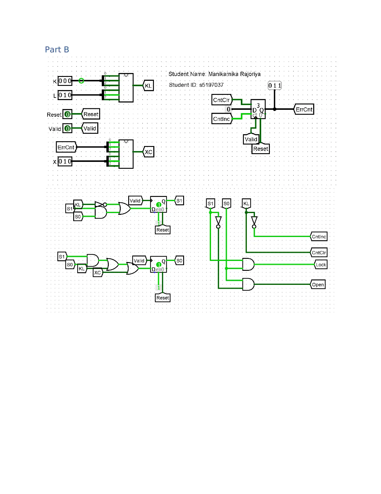
Part B makes use of comparator designed in Part A. It checks Key value with respect
to Lock value. And second instance of comparator checks incorrect sequences
entered with respect to allowed count for incorrect sequences.
There are two D flip flops for state machine. A flip flop is a memory element that
can hold the last input value it is triggered by an external clock again when it picks
the new value. The flip flops form the state variables S1 and S0. Together they can
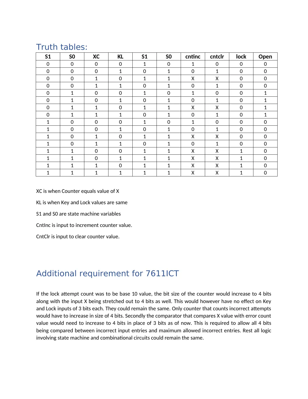
be used to represent up to 4 states of an FSM. The four states in our circuit are
Reset denoted by 00. Correct input key lock combination denoted by 01. Incorrect
key lock combination denoted by 10 and Lock state denoted by 11.
Machine Circuit Design Assignment Project_2

End of preview

Want to access all the pages? Upload your documents or become a member.

Related Documents
Introduction The digital clock makes use of two types
|3
|398
|42

Circuit Function: Decoder and Comparator for Lift Movement
|6
|1194
|63