HND in Manufacturing: Vehicle Systems and Technology - Activities
VerifiedAdded on 2023/03/30
|9
|1322
|333
Report
AI Summary
This report delves into vehicle systems and technology, specifically focusing on power steering and active suspension systems. It begins by outlining the major components and principles of operation for both hydromechanics-assisted and electro-mechanical power-assisted steering systems, highli...

Managing Activities 1
THE MANAGING ACTIVITIES
Name
Course
Tutor
University
City/state
Date Of Submission
THE MANAGING ACTIVITIES
Name
Course
Tutor
University
City/state
Date Of Submission
Paraphrase This Document
Need a fresh take? Get an instant paraphrase of this document with our AI Paraphraser
Managing Activities 2
TASK 1
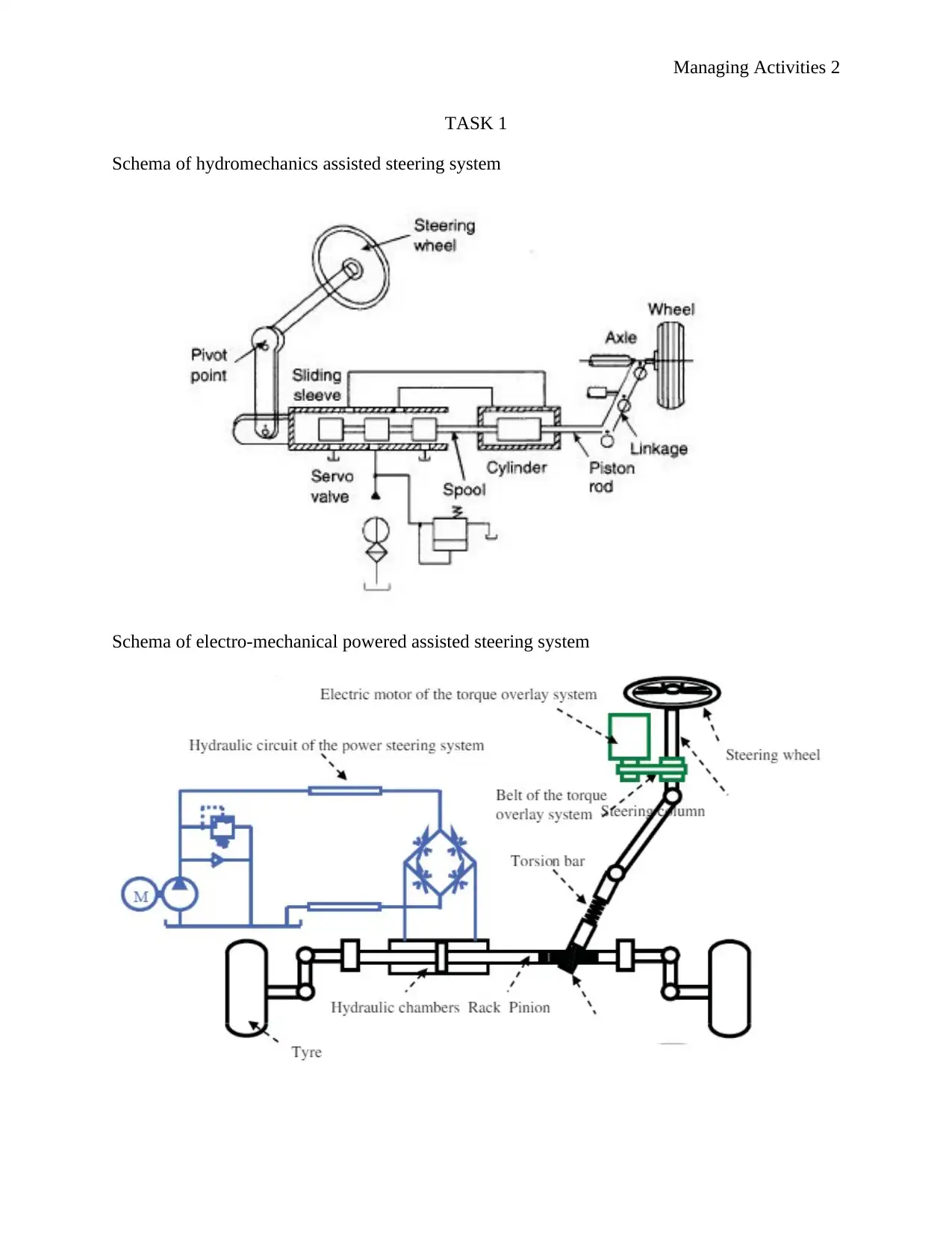
Schema of hydromechanics assisted steering system
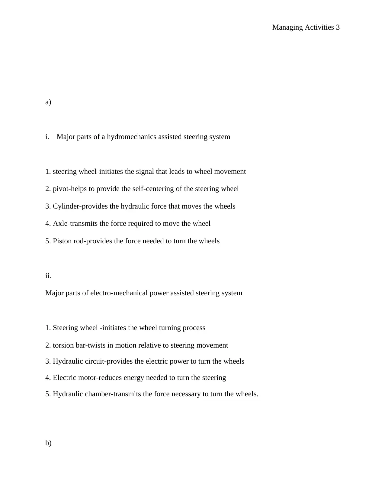
Schema of electro-mechanical powered assisted steering system
TASK 1
Schema of hydromechanics assisted steering system
Schema of electro-mechanical powered assisted steering system
Managing Activities 3
a)
i. Major parts of a hydromechanics assisted steering system
1. steering wheel-initiates the signal that leads to wheel movement
2. pivot-helps to provide the self-centering of the steering wheel
3. Cylinder-provides the hydraulic force that moves the wheels
4. Axle-transmits the force required to move the wheel
5. Piston rod-provides the force needed to turn the wheels
ii.
Major parts of electro-mechanical power assisted steering system
1. Steering wheel -initiates the wheel turning process
2. torsion bar-twists in motion relative to steering movement
3. Hydraulic circuit-provides the electric power to turn the wheels
4. Electric motor-reduces energy needed to turn the steering
5. Hydraulic chamber-transmits the force necessary to turn the wheels.
b)
⊘ This is a preview!⊘
Do you want full access?
Subscribe today to unlock all pages.

Trusted by 1+ million students worldwide
Managing Activities 4
Principle of operation of hydromechanics assisted steering system:
As denoted in the Research and Markets (2019), the process begins with the turning of the
steering wheel which sends a signal that causes the valve sleeve to move this in turn causes the
hydraulic oil to pour into the steering cylinder. This accumulation of oil causes the movement of
the piston rod which pushes the valve spool which moves the steering linkage which in turn
causes the movement of the wheel.
Principle of operation of electro-mechanical assisted steering system:
The electric power system supplements the force with which the driver turns the steering. The
system is controlled by an electric control unit which calculates the amount of power to be
produced so as to assist the driver when turning the steering, the signal produced is sent to the
electric motor which rotates the steering gear with a specific amount of force thus reducing the
amount of energy required to turn the steering wheel. At higher speeds the amount of assistance
provided by the electric system is lower than that provided at lower speeds.
c)
Advantages of an electro-mechanical steering over the hydromechanics system include;
b 1.performance-the electromechanical steering responds faster compared to the
hydromechanics system
b 2.design-the hydromechanics system has a more sophisticated design compared to the
electromechanical steering
b 3.environmental considerations-the hydromechanics system uses engine power hence more
fuel is consumed leading to higher emission on carbon dioxide the causes global warming while
the electro-mechanical system uses battery power hence it is more environment friendly
Paraphrase This Document
Need a fresh take? Get an instant paraphrase of this document with our AI Paraphraser
Managing Activities 5
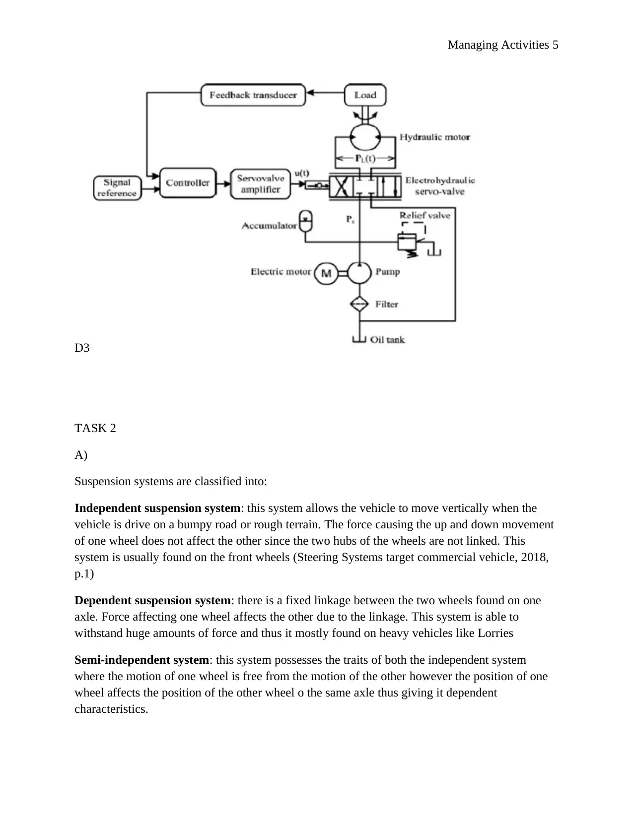
D3
TASK 2
A)
Suspension systems are classified into:
Independent suspension system: this system allows the vehicle to move vertically when the
vehicle is drive on a bumpy road or rough terrain. The force causing the up and down movement
of one wheel does not affect the other since the two hubs of the wheels are not linked. This
system is usually found on the front wheels (Steering Systems target commercial vehicle, 2018,
p.1)
Dependent suspension system: there is a fixed linkage between the two wheels found on one
axle. Force affecting one wheel affects the other due to the linkage. This system is able to
withstand huge amounts of force and thus it mostly found on heavy vehicles like Lorries
Semi-independent system: this system possesses the traits of both the independent system
where the motion of one wheel is free from the motion of the other however the position of one
wheel affects the position of the other wheel o the same axle thus giving it dependent
characteristics.
Managing Activities 6
B)
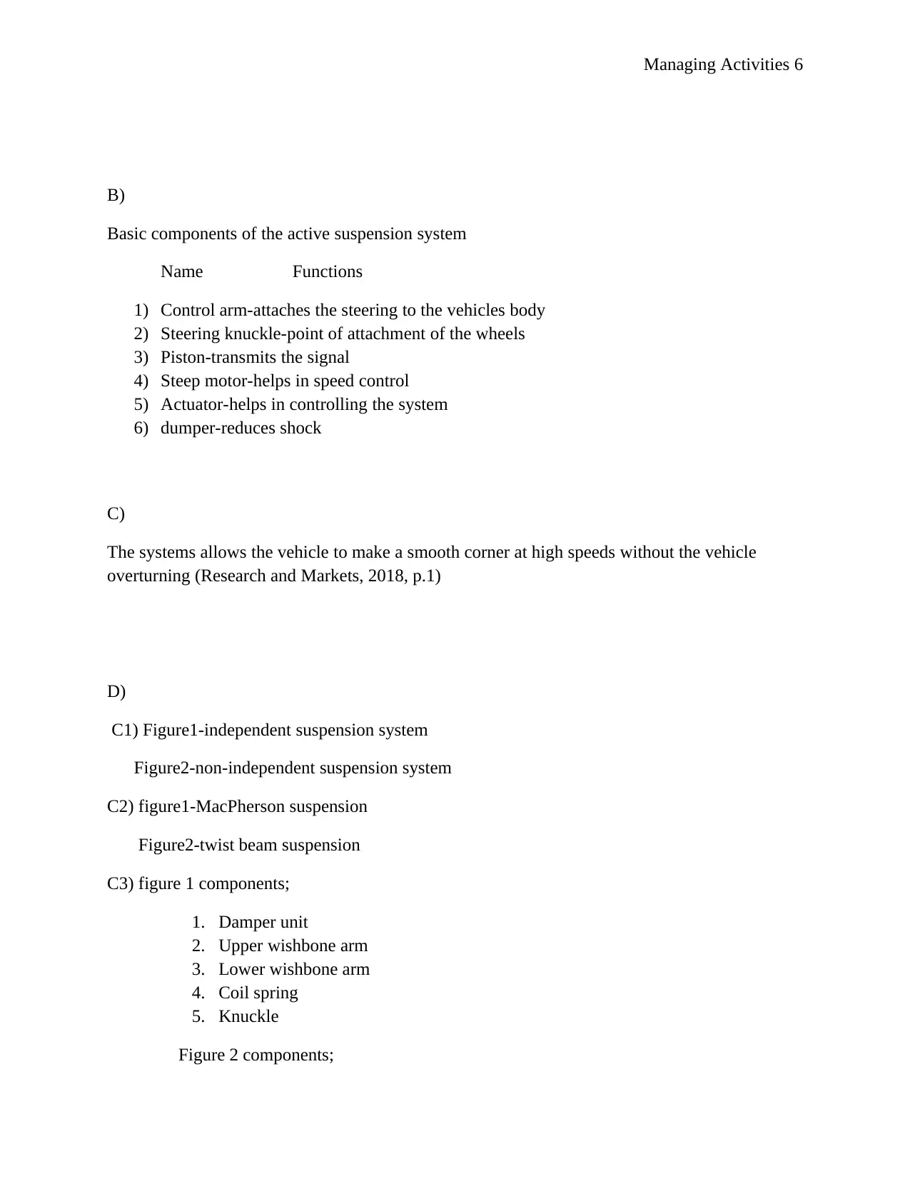
Basic components of the active suspension system
Name Functions
1) Control arm-attaches the steering to the vehicles body
2) Steering knuckle-point of attachment of the wheels
3) Piston-transmits the signal
4) Steep motor-helps in speed control
5) Actuator-helps in controlling the system
6) dumper-reduces shock
C)
The systems allows the vehicle to make a smooth corner at high speeds without the vehicle
overturning (Research and Markets, 2018, p.1)
D)
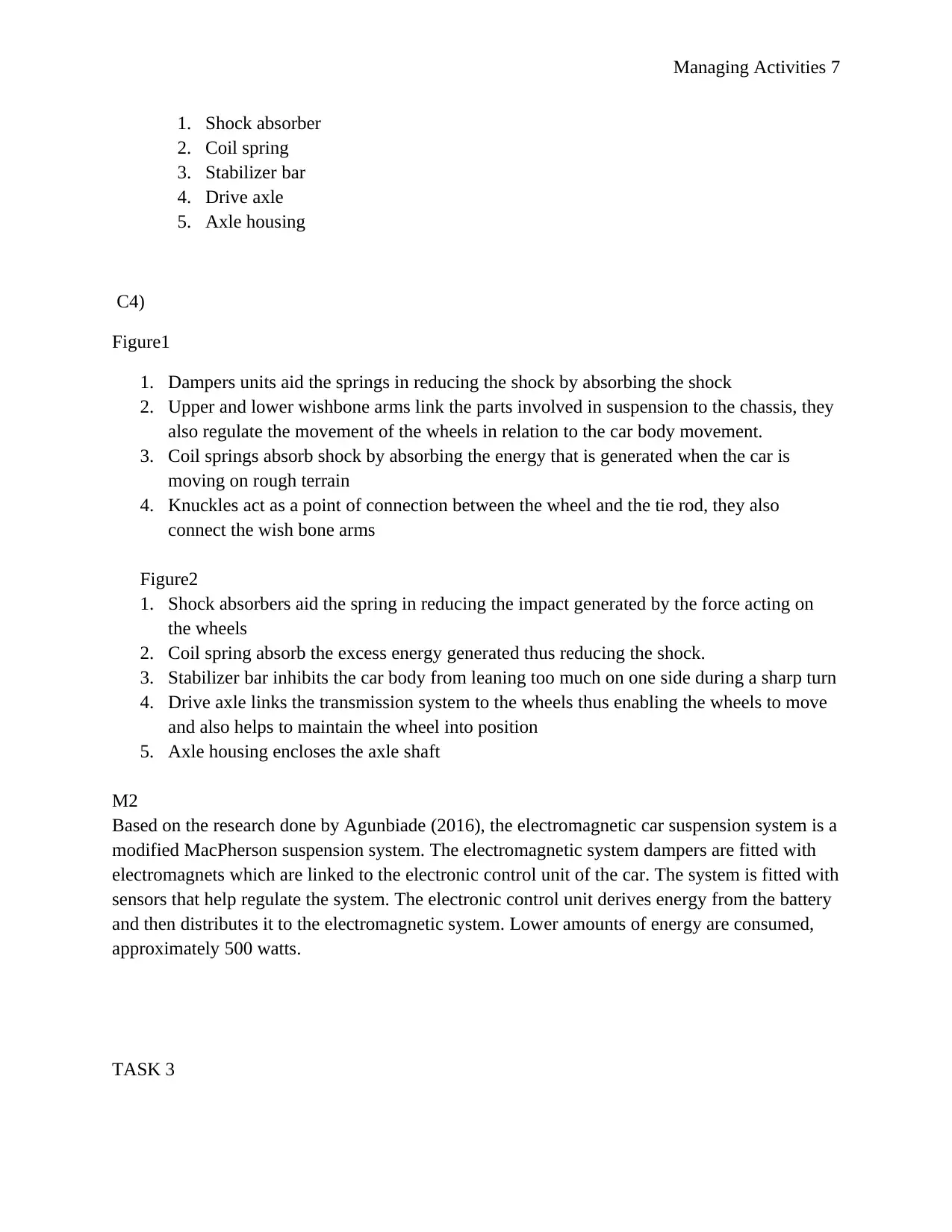
C1) Figure1-independent suspension system
Figure2-non-independent suspension system
C2) figure1-MacPherson suspension
Figure2-twist beam suspension
C3) figure 1 components;
1. Damper unit
2. Upper wishbone arm
3. Lower wishbone arm
4. Coil spring
5. Knuckle
Figure 2 components;
⊘ This is a preview!⊘
Do you want full access?
Subscribe today to unlock all pages.

Trusted by 1+ million students worldwide
Managing Activities 7
1. Shock absorber
2. Coil spring
3. Stabilizer bar
4. Drive axle
5. Axle housing
C4)
Figure1
1. Dampers units aid the springs in reducing the shock by absorbing the shock
2. Upper and lower wishbone arms link the parts involved in suspension to the chassis, they
also regulate the movement of the wheels in relation to the car body movement.
3. Coil springs absorb shock by absorbing the energy that is generated when the car is
moving on rough terrain
4. Knuckles act as a point of connection between the wheel and the tie rod, they also
connect the wish bone arms
Figure2
1. Shock absorbers aid the spring in reducing the impact generated by the force acting on
the wheels
2. Coil spring absorb the excess energy generated thus reducing the shock.
3. Stabilizer bar inhibits the car body from leaning too much on one side during a sharp turn
4. Drive axle links the transmission system to the wheels thus enabling the wheels to move
and also helps to maintain the wheel into position
5. Axle housing encloses the axle shaft
M2
Based on the research done by Agunbiade (2016), the electromagnetic car suspension system is a
modified MacPherson suspension system. The electromagnetic system dampers are fitted with
electromagnets which are linked to the electronic control unit of the car. The system is fitted with
sensors that help regulate the system. The electronic control unit derives energy from the battery
and then distributes it to the electromagnetic system. Lower amounts of energy are consumed,
approximately 500 watts.
TASK 3
Paraphrase This Document
Need a fresh take? Get an instant paraphrase of this document with our AI Paraphraser
Managing Activities 8
a)
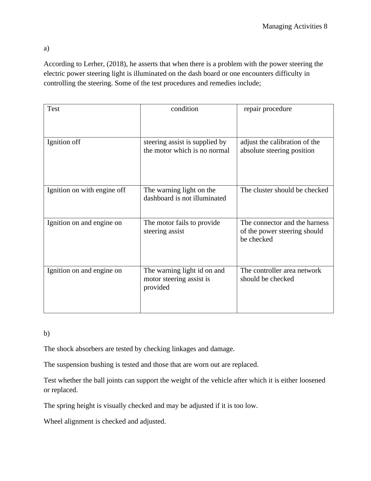
According to Lerher, (2018), he asserts that when there is a problem with the power steering the
electric power steering light is illuminated on the dash board or one encounters difficulty in
controlling the steering. Some of the test procedures and remedies include;
Test condition repair procedure
Ignition off steering assist is supplied by
the motor which is no normal
adjust the calibration of the
absolute steering position
Ignition on with engine off The warning light on the
dashboard is not illuminated
The cluster should be checked
Ignition on and engine on The motor fails to provide
steering assist
The connector and the harness
of the power steering should
be checked
Ignition on and engine on The warning light id on and
motor steering assist is
provided
The controller area network
should be checked
b)
The shock absorbers are tested by checking linkages and damage.
The suspension bushing is tested and those that are worn out are replaced.
Test whether the ball joints can support the weight of the vehicle after which it is either loosened
or replaced.
The spring height is visually checked and may be adjusted if it is too low.
Wheel alignment is checked and adjusted.
Managing Activities 9
List of references
‘Steering Systems target commercial vehicle’ (2014) ThomasNet News, p. 1.
Agunbiade, O., (2016) ‘Improving ground detection for unmanned vehicle systems in
environmental noise scenarios’, International Journal of Advanced Manufacturing Technology,
84(9–12), pp. 2719–2727.
Lerher, T. (2018) ‘Aisle changing shuttle carriers in autonomous vehicle storage and retrieval
systems’, International Journal of Production Research, 56(11), pp. 3859–3879.
Research and Markets (2AD) ‘Global Automotive Power Steering Systems Market 2017-2025
Forecast to Reach $35 Billion - Growing Efforts Towards Development of Steer-By-Wire
Systems - ResearchAndMarkets.com’, Business Wire (English), 2018
Research and Markets (3AD) ‘Autonomous Vehicles to 2027: A Detailed Review Featuring
Google, Nissan & Tesla - Research and Markets’, Business Wire (English), 2017 .
Research and Markets (3AD) ‘Global Steering System Market Report (2019 Edition): 2013-2023
Analysis & Outlook by Vehicle Type, Steering Type, Distribution Channel, Value and Volume -
ResearchAndMarkets.com’, Business Wire (English), 2019
Technavio Research (1AD) ‘Global Automotive Electro-Hydraulic Power Steering System
Market 2019-2023 to Post 11% CAGR| Technavio’, Business Wire (English), 2019
⊘ This is a preview!⊘
Do you want full access?
Subscribe today to unlock all pages.

Trusted by 1+ million students worldwide
1 out of 9
Related Documents
Your All-in-One AI-Powered Toolkit for Academic Success.
+13062052269
info@desklib.com
Available 24*7 on WhatsApp / Email
![[object Object]](/_next/static/media/star-bottom.7253800d.svg)
Unlock your academic potential
© 2024 | Zucol Services PVT LTD | All rights reserved.


