MIT Civil Engineering Steel Structure and Timber Design Project 2019
VerifiedAdded on 2023/03/31
|7
|1127
|170
Project
AI Summary
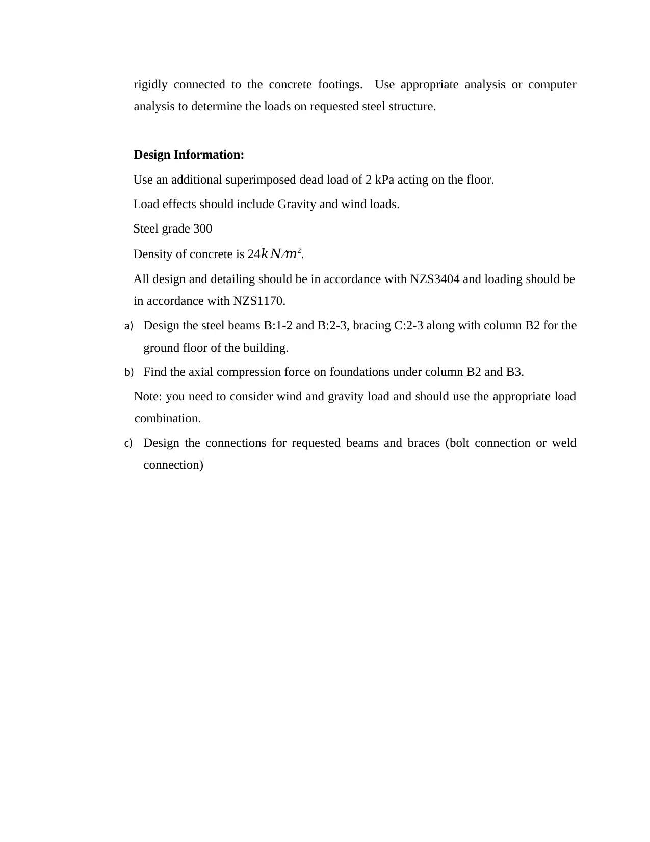
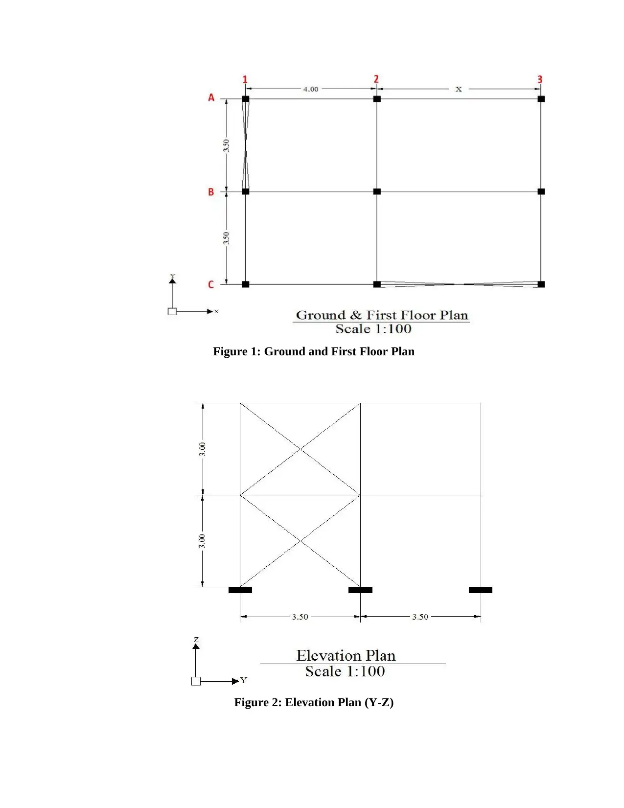
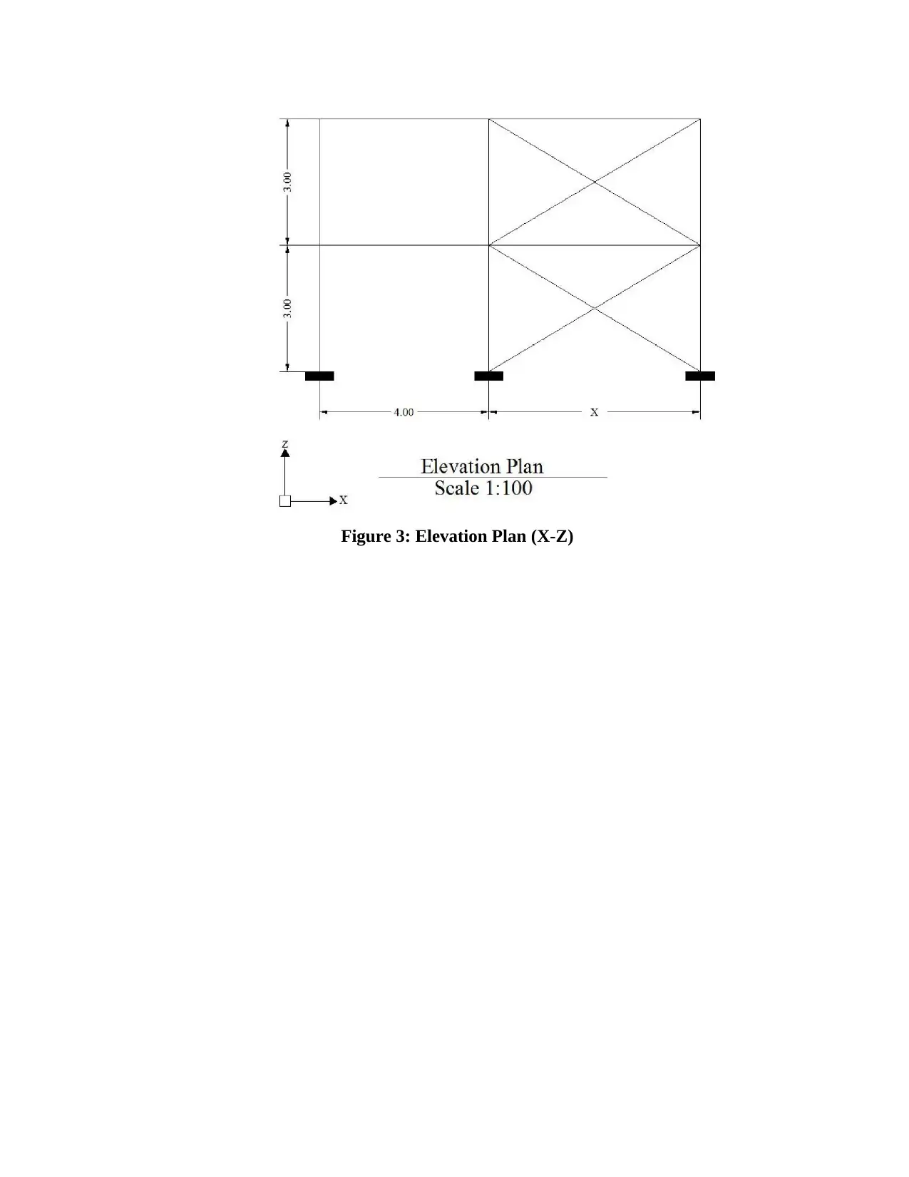
This project presents a comprehensive analysis of a steel structure design, adhering to NZS3404 and NZS1170 standards. The assignment begins with explanations of different load types including dead loads, imposed loads, and wind loads. It then differentiates between Ultimate Limit State (ULS) and Serviceability Limit State (SLS) design methodologies. The core of the project involves designing a two-story steel building located in Wellington, with detailed calculations of regional wind speed, terrain/height multipliers, wind direction multipliers, shielding multipliers, and topographical multipliers. These calculations are essential for determining the design wind speed and pressure. Furthermore, the project delves into the design of steel beams, bracing, and columns, including the determination of axial compression forces on foundations. It requires the consideration of both gravity and wind loads, alongside appropriate load combinations. The solution also addresses the design of connections for beams and braces, considering either bolt or weld connections based on the structural requirements. The project emphasizes practical application of structural engineering principles, integrating design information, loading considerations, and adherence to relevant standards.
1 out of 7

Your All-in-One AI-Powered Toolkit for Academic Success.
+13062052269
info@desklib.com
Available 24*7 on WhatsApp / Email
![[object Object]](/_next/static/media/star-bottom.7253800d.svg)
Copyright © 2020–2026 A2Z Services. All Rights Reserved. Developed and managed by ZUCOL.