Mass Moment of Inertia: Calculation and Application
VerifiedAdded on 2023/06/13
|12
|1174
|107
AI Summary
This article explains the calculation and application of mass moment of inertia in rotational motion. It covers three methods to determine the mass moment of inertia, including the geometric method, the pendulum method, and the work-energy method. The article also includes a system diagram, free body diagram, and results of the experiment. The subject is relevant to physics and engineering courses.
Contribute Materials
Your contribution can guide someone’s learning journey. Share your
documents today.
Mass moment of inertia
Prepared by,
Student Name:
Student Id:
Mentor:
Prepared by,
Student Name:
Student Id:
Mentor:
Secure Best Marks with AI Grader
Need help grading? Try our AI Grader for instant feedback on your assignments.
Contents
Introduction......................................................................................................................................3
System diagram...............................................................................................................................4
Free Body Diagram..........................................................................................................................6
Application of conservation of momentum.....................................................................................7
The WE (Work energy) method..................................................................................................7
Dimension specimen....................................................................................................................7
Method pendulum........................................................................................................................7
Results..............................................................................................................................................8
Discussion........................................................................................................................................9
Introduction
The factor of the assessment required in making sense of the mass photograph of idleness of it
focal point of gravity for two magnificent occurrence by methods for using three determined
strategies. One more trial in perspective of go to a choice the mass picture of lethargy making
utilization of the pendulum strategy and choose finding the partner post point of convergence of
gravity. The objective of this be prepared is to check the photograph of torpidity of a steel deal
using the geometric technique to devise an understanding of the recommendation existing near
everything else of condition of no action. The mass picture of condition of no advancement is a
measure of the confirmation of a remarkable body to consigned expanding pace, which is field to
its mass disseminating about its turn center point.
The additional away the mass spreading of the body is from the turn of flip, the better the
photograph of idleness, the more troublesome it's to rotate the body about that inside point. That
is used to pick the verbalization clatter whereby racket is the differential fragment of mass,
holding at the most astounding purpose of the need list the best goal to figure the gathering of
lethargy for an accumulation of mass turning cycle a center, for example, a wheel, by strategies
for setting the depiction of torpidity of each mass atom that makes the body. In this be instructed,
the photo of inaction of a wheel about its central concentration is directed by utilizing making
utilization of the geometric strategy. The three procedures being used to settle on a choice the
mass photograph of condition of no advancement to accord to the going with:
The Wheel and rotate pendulum procedure. The place a pendulum is related of the point
of convergence of the delineation.
The mass and geometry of blueprint is measure and after that then decision into a from
the way booklet for a plate.
The work and monstrosity process fuses into giving the circle and center demonstrate a
threat move down on a slant plane.
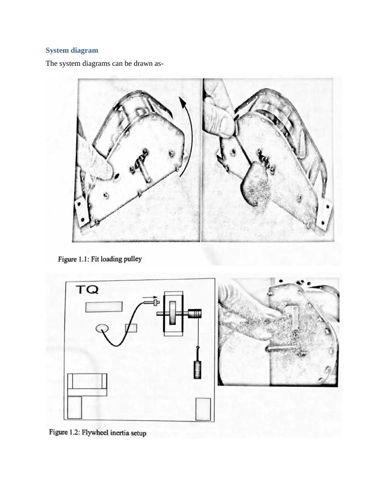
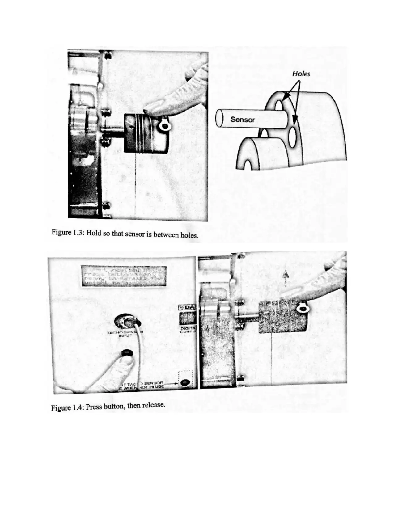
System diagram
The system diagrams can be drawn as-
The system diagrams can be drawn as-
Secure Best Marks with AI Grader
Need help grading? Try our AI Grader for instant feedback on your assignments.
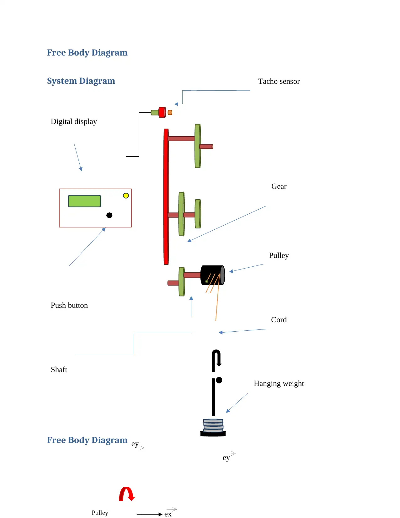
Free Body Diagram
System Diagram
Free Body Diagram
ey
Tacho sensor
Digital display
Hanging weight
Pulley
Gear
Cord
Push button
Shaft
Pulley ex
ey
System Diagram
Free Body Diagram
ey
Tacho sensor
Digital display
Hanging weight
Pulley
Gear
Cord
Push button
Shaft
Pulley ex
ey
From newton’s second law
mg−T =ma−−−−(1)
The tension of the cord is the force applies a torque on axis of rotation
TR=Iα
TR= Ia
R −−−−(2)
Substituting T into first equation
mg− Ia
R2 =ma−−−−(3)
From equation 3 angler acceleration and moment of inertia can be obtained.
ez
ex
Mass
Mg
T1
acceleratio
n
α
Iα
T1
Mg
FN
Tension of cord
Paraphrase This Document
Need a fresh take? Get an instant paraphrase of this document with our AI Paraphraser
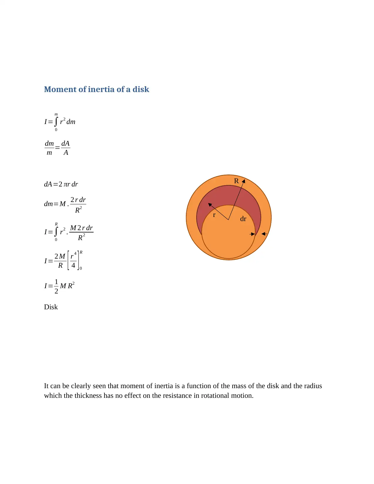
Moment of inertia of a disk
I =∫
0
m
r2 dm
dm
m = dA
A
dA=2 πr dr
dm=M . 2 r dr
R2
I =∫
0
R
r2 . M 2 r dr
R2
I = 2 M
R [ r 4
4 ] 0
R
I = 1
2 M R2
Disk
It can be clearly seen that moment of inertia is a function of the mass of the disk and the radius
which the thickness has no effect on the resistance in rotational motion.
dr
r
R
I =∫
0
m
r2 dm
dm
m = dA
A
dA=2 πr dr
dm=M . 2 r dr
R2
I =∫
0
R
r2 . M 2 r dr
R2
I = 2 M
R [ r 4
4 ] 0
R
I = 1
2 M R2
Disk
It can be clearly seen that moment of inertia is a function of the mass of the disk and the radius
which the thickness has no effect on the resistance in rotational motion.
dr
r
R
Application of Conservation of Momentum
∑⃗ Fext= ˙⃑Gsys=ma
( Fg −FT )⃗ ey=m ¨y⃗ e y
¨y=g− 1
mb
FT
∑⃗ M ext
o
= ˙⃑H sys= d
dt ( I⃑ ω )
∑ (⃗ r ×⃗ F ) = d
dt ( I⃗ ω )
R⃗ eX × FT⃗ e y= d
dt ( ^I⃗ ω )
R FT⃗ eZ=IZZ ˙ωZ⃗ eZ
R FT =I ZZ ˙ωZ
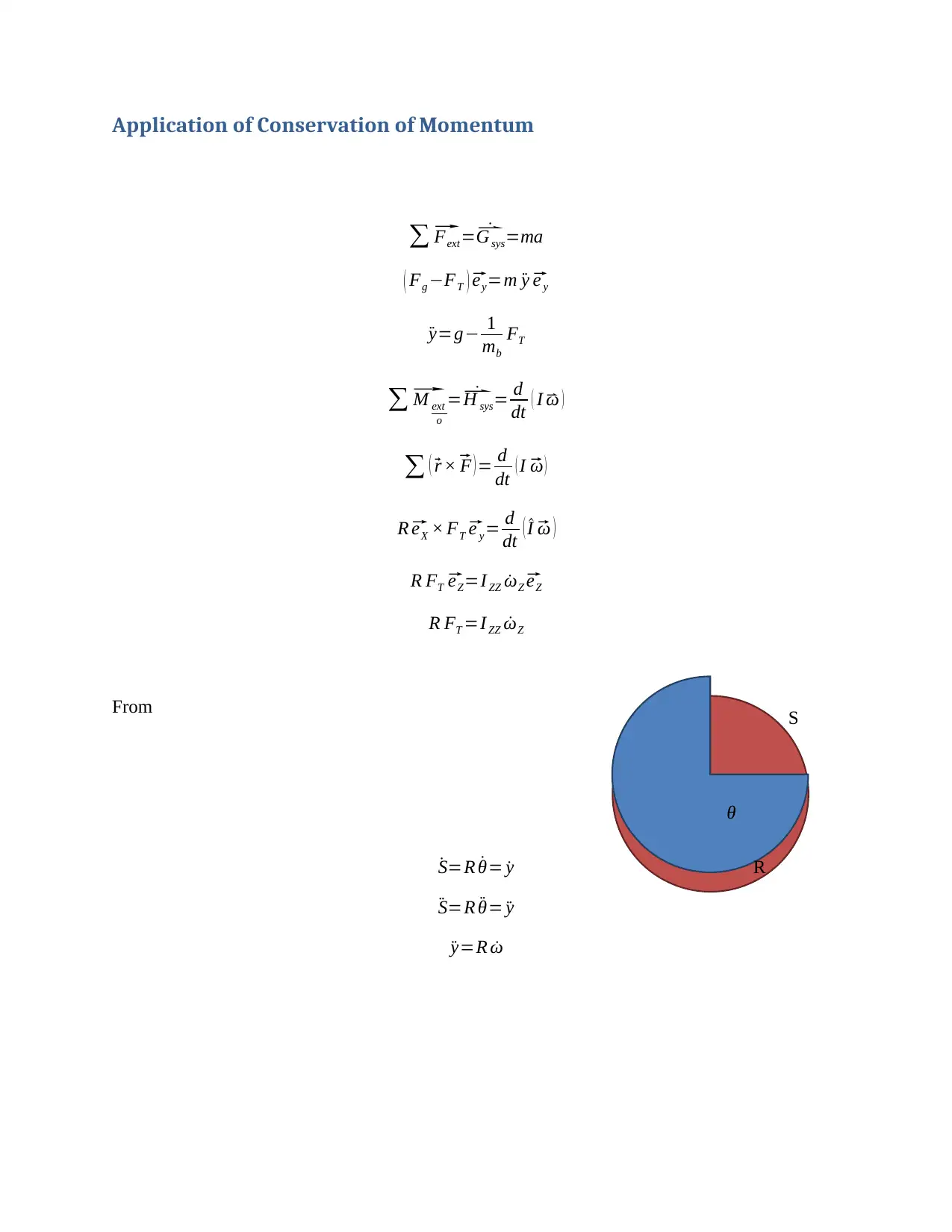
From
˙S=R ˙θ= ˙y
¨S=R ¨θ= ¨y
¨y=R ˙ω
θ
S
R
∑⃗ Fext= ˙⃑Gsys=ma
( Fg −FT )⃗ ey=m ¨y⃗ e y
¨y=g− 1
mb
FT
∑⃗ M ext
o
= ˙⃑H sys= d
dt ( I⃑ ω )
∑ (⃗ r ×⃗ F ) = d
dt ( I⃗ ω )
R⃗ eX × FT⃗ e y= d
dt ( ^I⃗ ω )
R FT⃗ eZ=IZZ ˙ωZ⃗ eZ
R FT =I ZZ ˙ωZ
From
˙S=R ˙θ= ˙y
¨S=R ¨θ= ¨y
¨y=R ˙ω
θ
S
R
¨y=g−( 1
R ) IZZ
mbR
¨y= g
( 1+ IZZ
mb R2 )
¨y= g
(1+ ma
2 mb )−−−−− ( linear accleration )
Also Angular momentum conserved Li=Lf , which L is the rotational kinetic energy 1
2 I ω2, and I
is 1
2 mr 2.
The conservation of momentum:
1
2 I ω2
i
+ mghi =mg hf + 1
2 m v2 + 1
2 I ω2−−−−−−(1)
The disk is stationery and there is no torque applied to accelerate it or maintain it velocity which
leads to 1
2 I ω2
i
=0, the remaining energy in the start of the system is the potential energy from
the hanging mass, as for the disk potential energy is neglected do to the unchanged of value in
initial and final status.
mg hi=mg hf +1
2 m v2+ 1
2 I ω2−−−−−−(2)
The final position observed is the ground surface hf =0 that contribute to mg hf =0.
mg hi= 1
2 m v2 + 1
2 I ω2−−−−−−(3)
Secure Best Marks with AI Grader
Need help grading? Try our AI Grader for instant feedback on your assignments.
From equation 3 several parameters can be obtained such as distance of falling mass, velocity of
falling mass, angler velocity and finally kinetic energy.
Results
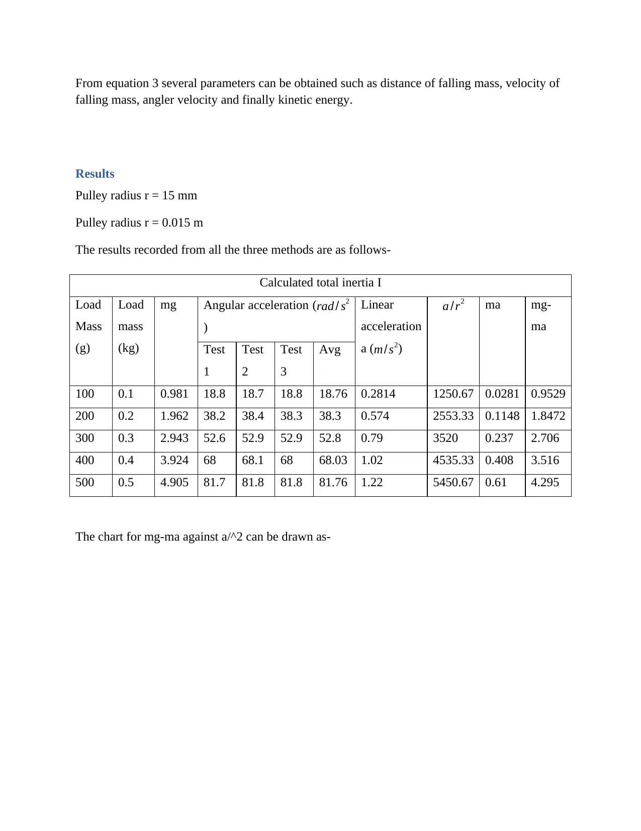
Pulley radius r = 15 mm
Pulley radius r = 0.015 m
The results recorded from all the three methods are as follows-
Calculated total inertia I
Load
Mass
(g)
Load
mass
(kg)
mg Angular acceleration (rad / s2
)
Linear
acceleration
a (m/s2)
a /r2 ma mg-
ma
Test
1
Test
2
Test
3
Avg
100 0.1 0.981 18.8 18.7 18.8 18.76 0.2814 1250.67 0.0281 0.9529
200 0.2 1.962 38.2 38.4 38.3 38.3 0.574 2553.33 0.1148 1.8472
300 0.3 2.943 52.6 52.9 52.9 52.8 0.79 3520 0.237 2.706
400 0.4 3.924 68 68.1 68 68.03 1.02 4535.33 0.408 3.516
500 0.5 4.905 81.7 81.8 81.8 81.76 1.22 5450.67 0.61 4.295
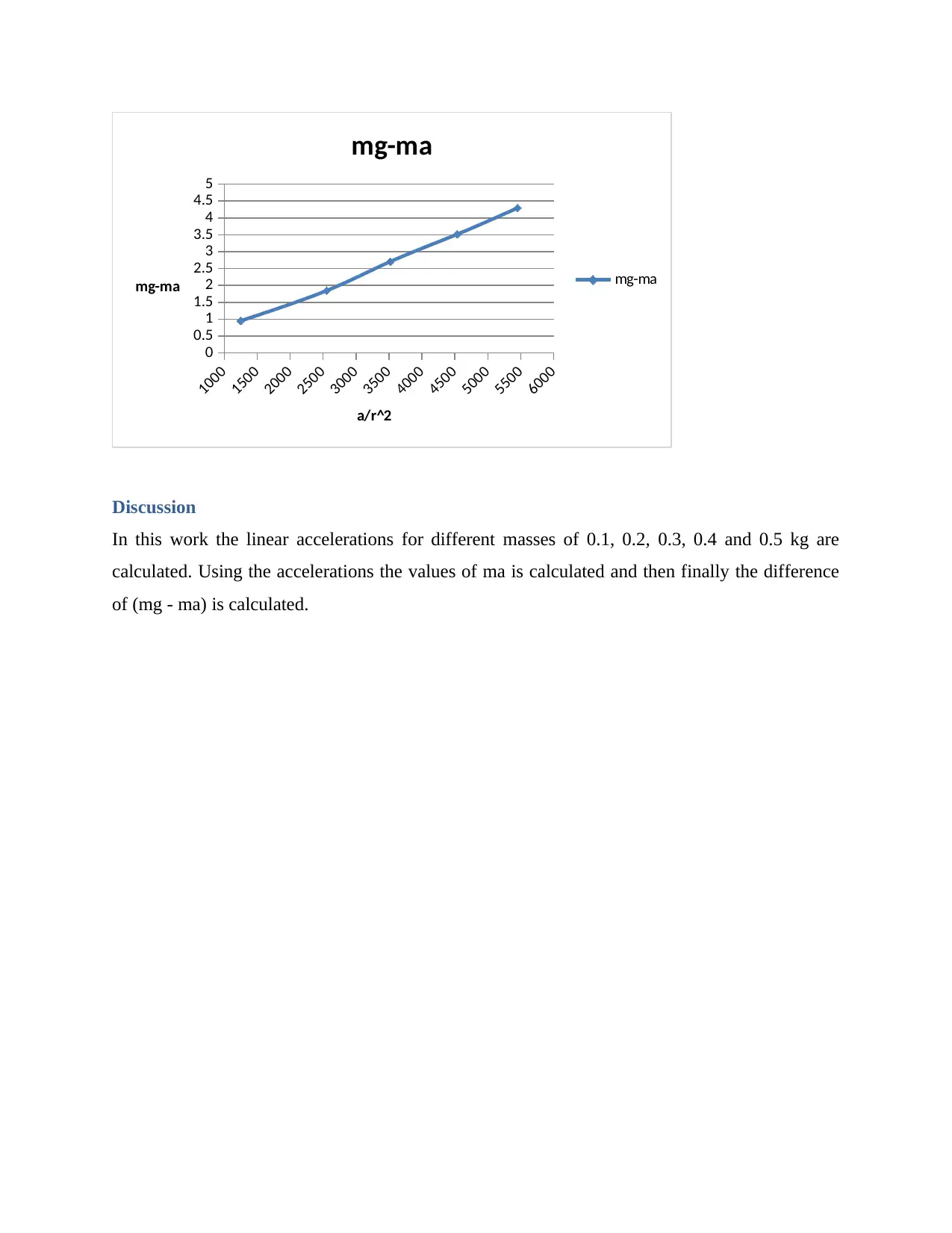
The chart for mg-ma against a/^2 can be drawn as-
falling mass, angler velocity and finally kinetic energy.
Results
Pulley radius r = 15 mm
Pulley radius r = 0.015 m
The results recorded from all the three methods are as follows-
Calculated total inertia I
Load
Mass
(g)
Load
mass
(kg)
mg Angular acceleration (rad / s2
)
Linear
acceleration
a (m/s2)
a /r2 ma mg-
ma
Test
1
Test
2
Test
3
Avg
100 0.1 0.981 18.8 18.7 18.8 18.76 0.2814 1250.67 0.0281 0.9529
200 0.2 1.962 38.2 38.4 38.3 38.3 0.574 2553.33 0.1148 1.8472
300 0.3 2.943 52.6 52.9 52.9 52.8 0.79 3520 0.237 2.706
400 0.4 3.924 68 68.1 68 68.03 1.02 4535.33 0.408 3.516
500 0.5 4.905 81.7 81.8 81.8 81.76 1.22 5450.67 0.61 4.295
The chart for mg-ma against a/^2 can be drawn as-
1000
1500
2000
2500
3000
3500
4000
4500
5000
5500
6000
0
0.5
1
1.5
2
2.5
3
3.5
4
4.5
5
mg-ma
mg-ma
a/r^2
mg-ma
Discussion
In this work the linear accelerations for different masses of 0.1, 0.2, 0.3, 0.4 and 0.5 kg are
calculated. Using the accelerations the values of ma is calculated and then finally the difference
of (mg - ma) is calculated.
1 out of 12
Your All-in-One AI-Powered Toolkit for Academic Success.
+13062052269
info@desklib.com
Available 24*7 on WhatsApp / Email
![[object Object]](/_next/static/media/star-bottom.7253800d.svg)
Unlock your academic potential
© 2024 | Zucol Services PVT LTD | All rights reserved.