Massive MIMO Channel: Analysis of Channel Models and Simulation
VerifiedAdded on 2023/04/23
|56
|11480
|99
Thesis and Dissertation
AI Summary
This thesis provides a comprehensive analysis of Massive MIMO channels, focusing on channel modeling, simulation, and performance evaluation. It begins with an introduction to wireless communication challenges and the role of MIMO technology in addressing issues like spectrum and energy efficiency. The thesis explores classic MIMO channel models, including the WINNER II model and Cluster Delay Line models, before delving into Massive MIMO channel modeling, antenna configurations, and channel mode estimation. Key parameters such as spectral efficiency, energy efficiency, and correlation factor are considered. The methodology involves channel modeling and simulation, with a detailed network setup and visualization. The simulation results are presented and analyzed, followed by a conclusion and discussion of further work and challenges. The thesis aims to enhance the understanding of Massive MIMO channels and contribute to the development of efficient wireless communication systems. Desklib provides access to this thesis and other study resources for students.
Thesis On Massive MIMO Channel 1
THESIS ON MASSIVE MIMO CHANNEL
Name of Author
Course
Instructor
Institution
Location
Date
THESIS ON MASSIVE MIMO CHANNEL
Name of Author
Course
Instructor
Institution
Location
Date
Paraphrase This Document
Need a fresh take? Get an instant paraphrase of this document with our AI Paraphraser
Thesis On Massive MIMO Channel 2
Abstract
There has been tremendous development in the technology sector, which has
seen the growth of many wireless devices connected together. The devices are linked to
each other through wireless networks. Thus, it is necessary for these devices to have a
greater throughput in order to allow applications such as movies, real-time videos,
games as well as voice. The growth in terms of the required throughput of these devices
has as well been on the rise. This growth has sparked for a number of factors which are
related to the network capacity being insufficient and high energy consumption which
eventually results in high carbon emission.
In a nutshell, the energy efficiency and spectrum efficiency has been the major
issues. MIMO has been regarded as one of the devices which can help address these
issues due to its admirable features and characteristics. To evaluate the performance of
wireless communication networks, there are some scenarios which should be taken into
account, such as the characteristics of the signals in radio under varied environments.
The process of evaluation begins with the presentation and classification of the antenna
array configurations. These process directly affects the performance of the system as
well as its channel models.
Thereafter, the simulations measurements are presented in order to have a clear
view of the features of the massive MIMO channels. On the other hand, there are some
conditions which have to be met by the incoming wireless systems. For instance, the
incoming wireless systems should be able to serve many operators concurrently, the
consumption rate should be as low as possible and also it should have a high
Thesis On Massive MIMO Channel 3
throughput. A number of researchers have been attracted by the MIMO technology,
which seems to be the solution for the upcoming 5G wireless networks.
There is a need to come up with an accurate model of the MIMO channels for us
to effectively evaluate its performance as well as to classifying its propagation channels.
After coming up with the model, we need to run it through a simulation tool for us to
establish some of the possible future problems or rather errors. However, one will quite
agree that the processing of a channel is one which is very complicated. In between the
transmitter-receiver pairs, a wideband channel should be established, with the
correlation issues arising.
Taking into considerations these factors, the MIMO channel models get tested
using the practical evaluation and theoretical analysis. In this research paper, the
original MIMO system will be modified a bit in order to come up with a system that has
enhanced efficiency, with regards to, the spectrum efficiency and energy efficiency.
⊘ This is a preview!⊘
Do you want full access?
Subscribe today to unlock all pages.
Trusted by 1+ million students worldwide
Thesis On Massive MIMO Channel 4
Table of Contents
Abstract............................................................................................................................2
List of Figures…………………………………………………………………………7
List of Figures………………………………………………………………………………………………………………7
List of Tables………………………………………………………………………………………………………………8
Introduction.....................................................................................................................8
Project Motivation...................................................................................................................8
Wireless communication........................................................................................................9
Definition of Communication.............................................................................................9
1.3 MIMO overview.............................................................................................................10
1.3.1 Definition..................................................................................................................10
1.3.2 MIMO applications.................................................................................................12
1.4.1 Features of Massive MIMO.......................................................................................13
1.4.2 Comparison between Massive MIMO and other traditional wireless
communications................................................................................................................14
1.4.3 Massive MIMO Uplink and Downlink Transmission..............................................16
1.5 Thesis outline...................................................................................................................17
2 Classic MIMO Channel Model..................................................................................18
2.1 The Role of Channel Models in Communication System Development.........................18
2.2 WINNER Generic Channel Model...................................................................................20
2.2.1 Modeled parameters.................................................................................................20
2.2.2 Winner II Modeling Process....................................................................................21
2.2.2.1 Model Structure.....................................................................................................21
2.3 Cluster Delay Line Model............................................................................................22
2.3.1 Cluster Delay Line models for mobile and portable scenarios...................................23
2.3.2 Cluster Delay Line models for fixed feeder links......................................................23
Massive MIMO Channel Modeling...............................................................................24
3.2 Antenna Configuration...................................................................................................25
3.3 Channel Mode Estimation...............................................................................................27
Case scenario.....................................................................................................................28
Paraphrase This Document
Need a fresh take? Get an instant paraphrase of this document with our AI Paraphraser
Thesis On Massive MIMO Channel 5
3.4 Parameters considered in the evaluation of Massive MIMO............................................29
3.4.1 Spectral efficiency.....................................................................................................29
3.4.2 Energy efficiency......................................................................................................29
3.5 Correlation Factor..........................................................................................................30
3.5.1 Definition..................................................................................................................30
3.5.2 Example of correlation impact: Exponential correlation matrix................................30
3.5.2.2 Exponential Correlation Matrix Model.................................................................32
4. METHODOLOGY....................................................................................................35
4.1 Channel modeling...........................................................................................................35
4.1.1 Network Setup...........................................................................................................35
4.1.2 Vizualization.............................................................................................................37
4.2 Simulation.......................................................................................................................38
5 Simulation of Massive MIMO............................................................................................39
5.1 Simulation configuration (diagram, scenario, parameters)...............................................40
5.1.1.2 C1 Scenario............................................................................................................40
5.2 Network layout setup........................................................................................................41
Fig 5-1: Network layout simulation output.............................................................................42
5.3 Simulation result.............................................................................................................42
5.4 Conclusion................................................................................................................46
6 Summary and Further work.................................................................................................47
6.2 Further Challenges...........................................................................................................47
References......................................................................................................................49
Appendix A: definitions................................................................................................52
Thesis On Massive MIMO Channel 6
Keywords
Wireless communication systems.
Channel modelling
Massive MIMO
Correlation
Energy consumption
Channel simulation
5G
List of Abbreviations
AA Antenna Array
Keywords
Wireless communication systems.
Channel modelling
Massive MIMO
Correlation
Energy consumption
Channel simulation
5G
List of Abbreviations
AA Antenna Array
⊘ This is a preview!⊘
Do you want full access?
Subscribe today to unlock all pages.
Trusted by 1+ million students worldwide
Thesis On Massive MIMO Channel 7
AoA Angle of Arrival
AoD Angle of departure
BER Bit Error Rate
CSI Channel State Information
DoD Delay of departure
DoA Delay of Arrival
EE Energy efficiency
FDD Frequency-division duplex
GC Group Concept
HSDPA High-Speed Downlink Packet Access
LOS Line of sight
LS Large scale
MISO Multiple-Input Single-Output
MIMO Massive Input Massive Output
NLOS Non-Line of Sight
SER Symbol Error Rate
SCM Spatial channel model
SCME Spatial Chanel medium extended
SIMO Single Input Multiple Output
SISO Single input Single Output
SE Spectrum efficiency
SIMO Single-Input Multiple-Output
TDD Time-division duplex.
ULA Uniform linear array
UCA Uniform circular array
UMTS Universal Mobile Telecommunications System
WP5 Word Package 5
3GPP/3GPP2 Third generation partner program/2
List of Figures
Fig 1.1: a wireless digital communication system
Fig 1.2: The MIMO channel.
Fig 2.1: WINNER Channel Model Process
Fig 3.1: Massive MIMO channel models
Fig 3.2: UCA & ULA representation
Fig 3.3: Uplink and Downlink repartition
Fig 5.1: Network layout simulation output
Fig 5.2: SER/SNR simulation output for A1/C1
Paraphrase This Document
Need a fresh take? Get an instant paraphrase of this document with our AI Paraphraser
Thesis On Massive MIMO Channel 8
Fig 5.3: BER/SNR simulation output for A1/C1
Fig 5.4: BER/SNR simulation for A1 (V=1&0.1ms)
Fig 5.5: SER/SNR simulation for A1 (V=1&0.1ms)
Fig 5.6: BER/SNR simulation for A1 (NLOS/LOS)
List of Tables
Table 1.1: Features of Massive MIMO.
Table 1.2: Difference between MU-MIMO and Massive MIMO
Table 2.1: LS and Support parameters classification
Table 5-1: SNR, BER, SER values A1/C1 scenarios
Introduction
Project Motivation
To comprehend the motivation behind this project, it is significant to learn about
the different challenges which are experienced in the wireless communication system.
Thesis On Massive MIMO Channel 9
Basically, a wireless communication system is composed of signal paths which are
transmitted from the BS to the MS receiver without any guiding medium (Marzetta,
2015). This implies that the signal is exposed to collision with some of the reflected
components such as scatters. The reflection can be aided by objects such as buildings
which deflect the transmitted signal. Multiple signal components are receipted at the
receiver which is then divided into two categories for preparation; NLOS and LOS.
Hence, we can comfortably define wireless communication as a multipath
propagation environment that comprises of superposition of radio waves. When the
signals are superimposed, there can either be constructive interference whereby the
signal gets enhanced, or destructive interference which leads to attenuation of the signal
being transmitted. When destructive interference occurs, multipath fading, shadowing
and path loss takes place (Sanayei & Nosratinia, 2004).
An effective wireless transmission calls for the keen design of the channel
impulse. Intelligent terminals have come up and can be found on some smartphones
following the advancement of newer technologies. Mostly, the users will be in need of
transmission of data on daily basis, without buffering. The upcoming 5G mobile system
will somehow be better as compared to the 4G system which also seems to be a bit
faster. Life has greatly been enhanced with the development of mobile, hence, it is an
obligation to continue offering better services in terms of mobile communication (Babu
& Rao, 2011).
Wireless communication
Definition of Communication
Communication is the process by which information is channeled from one
person to the other by the help of a medium. The communication process involves both
⊘ This is a preview!⊘
Do you want full access?
Subscribe today to unlock all pages.
Trusted by 1+ million students worldwide
Thesis On Massive MIMO Channel 10
the sender and the receiver via a medium channel. Communication can exist in many
ways, for instance, we can have oral communication, digital communication or body
language. When we talk about digital communication, one aspect that rings to the mind
is the signal medium that enables message to be transmitted from the sender to the
receiver. The transmitted signals undergoes the process of modulation and
demodulation.
These processes are meant to enhance both the frequency and amplitude, by
varying them up and back to the normal state so that the quality of the signal is
maintained. The signal is in terms of binary codes (0s and 1s), which gets modulated
into a complex sequence (Chen et al., 2005). The invention of Wireless communication
can be dated back to the nineteenth century and apparently it stands out to be one of the
best means of communication. This is because the world has been globally reduced into
a mere one community through wireless communication which requires no channel
medium nor electric conductors.
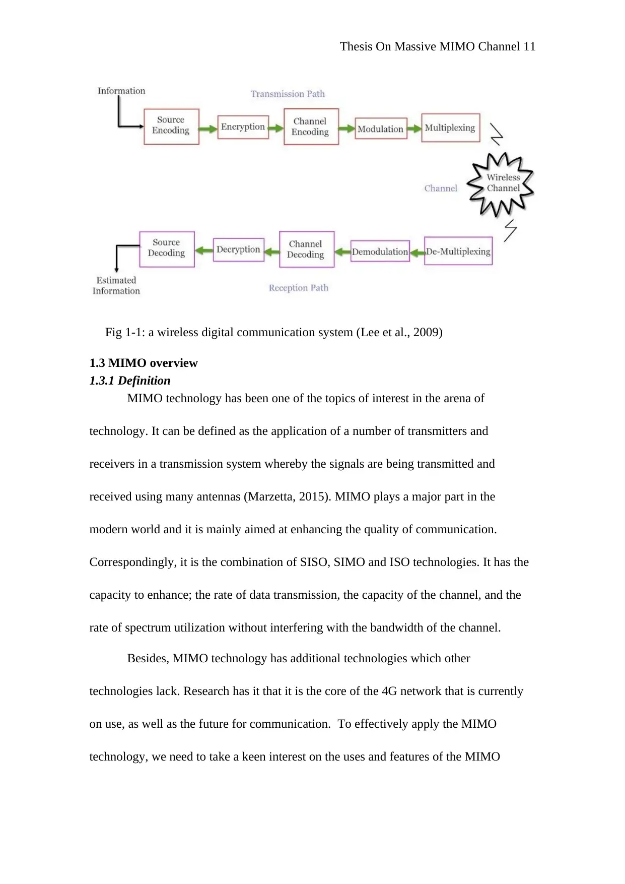
The various parameters which constitute the wireless communication are; radio
frequency, infrared radio, satellite, etc. There exists a number of wireless
communication users, with the mobile phones being the chief utility and also consumes
less amount of energy. This communication allows for information to be sent over a
wide range of place, as opposed to just individual persons. The diagram below shows
how information is transmitted to the receiver from the transmitter in a digital wireless
communication system (Liu et al., 2013)
the sender and the receiver via a medium channel. Communication can exist in many
ways, for instance, we can have oral communication, digital communication or body
language. When we talk about digital communication, one aspect that rings to the mind
is the signal medium that enables message to be transmitted from the sender to the
receiver. The transmitted signals undergoes the process of modulation and
demodulation.
These processes are meant to enhance both the frequency and amplitude, by
varying them up and back to the normal state so that the quality of the signal is
maintained. The signal is in terms of binary codes (0s and 1s), which gets modulated
into a complex sequence (Chen et al., 2005). The invention of Wireless communication
can be dated back to the nineteenth century and apparently it stands out to be one of the
best means of communication. This is because the world has been globally reduced into
a mere one community through wireless communication which requires no channel
medium nor electric conductors.
The various parameters which constitute the wireless communication are; radio
frequency, infrared radio, satellite, etc. There exists a number of wireless
communication users, with the mobile phones being the chief utility and also consumes
less amount of energy. This communication allows for information to be sent over a
wide range of place, as opposed to just individual persons. The diagram below shows
how information is transmitted to the receiver from the transmitter in a digital wireless
communication system (Liu et al., 2013)
Paraphrase This Document
Need a fresh take? Get an instant paraphrase of this document with our AI Paraphraser
Thesis On Massive MIMO Channel 11
Fig 1-1: a wireless digital communication system (Lee et al., 2009)
1.3 MIMO overview
1.3.1 Definition
MIMO technology has been one of the topics of interest in the arena of
technology. It can be defined as the application of a number of transmitters and
receivers in a transmission system whereby the signals are being transmitted and
received using many antennas (Marzetta, 2015). MIMO plays a major part in the
modern world and it is mainly aimed at enhancing the quality of communication.
Correspondingly, it is the combination of SISO, SIMO and ISO technologies. It has the
capacity to enhance; the rate of data transmission, the capacity of the channel, and the
rate of spectrum utilization without interfering with the bandwidth of the channel.
Besides, MIMO technology has additional technologies which other
technologies lack. Research has it that it is the core of the 4G network that is currently
on use, as well as the future for communication. To effectively apply the MIMO
technology, we need to take a keen interest on the uses and features of the MIMO
Thesis On Massive MIMO Channel 12
channels. Processing of the antenna arrays, individual antennas and antenna arrays
needs the realization of the expansion of MIMO channels capacity.
Originally, the research on the MIMO channels did not take into account all the
antennas since they seemed to be irrelevant with the individual antennas being
independent. Hence, to come up with an effective MIMO channel, there is a need to
develop, a link level and system level MIMO channel models for dissimilar scenarios.
(Kim et al., 2014). Evidence from the previous researches indicates that a number of
institutions and researches have been detailing theoretical information with regards to
the MIMO channel technology. Further, they have provided recommendations on the
simulation and evaluation of the MIMO channels. It is no doubt that their efforts have
seen the improvement of the MIMO channels technology, with standardization of the
model specifications.
This paper will entirely focus on some specific areas such as the 3GPP/3GPP2
(SCM), extended model (SCME), and the WP5 channel model of the WINNER II
project. The winner II project forms the background to the MIMO project. However, it
requires a lot of future modifications for it to augur well with the challenges that arise.
The hope is that future research will contribute to standardizing the mobile
communication systems. The diagram below shows the MIMO channel
⊘ This is a preview!⊘
Do you want full access?
Subscribe today to unlock all pages.
Trusted by 1+ million students worldwide
1 out of 56
Related Documents


Your All-in-One AI-Powered Toolkit for Academic Success.
+13062052269
info@desklib.com
Available 24*7 on WhatsApp / Email
![[object Object]](/_next/static/media/star-bottom.7253800d.svg)
Unlock your academic potential
Copyright © 2020–2026 A2Z Services. All Rights Reserved. Developed and managed by ZUCOL.