Material Testing using Scientific Method - Desklib
VerifiedAdded on 2023/06/07
|23
|971
|348
AI Summary
This presentation covers the topics of superposition, Thevenin equivalent circuits, RLC series circuits, and SI unit conversions in material testing using scientific method. It includes circuit diagrams, calculations, and final results. Desklib offers solved assignments, essays, and dissertations on these topics.
Contribute Materials
Your contribution can guide someone’s learning journey. Share your
documents today.
MATERIAL TESTING USING
SCIENTIFIC METHOD
SCIENTIFIC METHOD
Secure Best Marks with AI Grader
Need help grading? Try our AI Grader for instant feedback on your assignments.
Superposition, The veninSuperposition, The venin
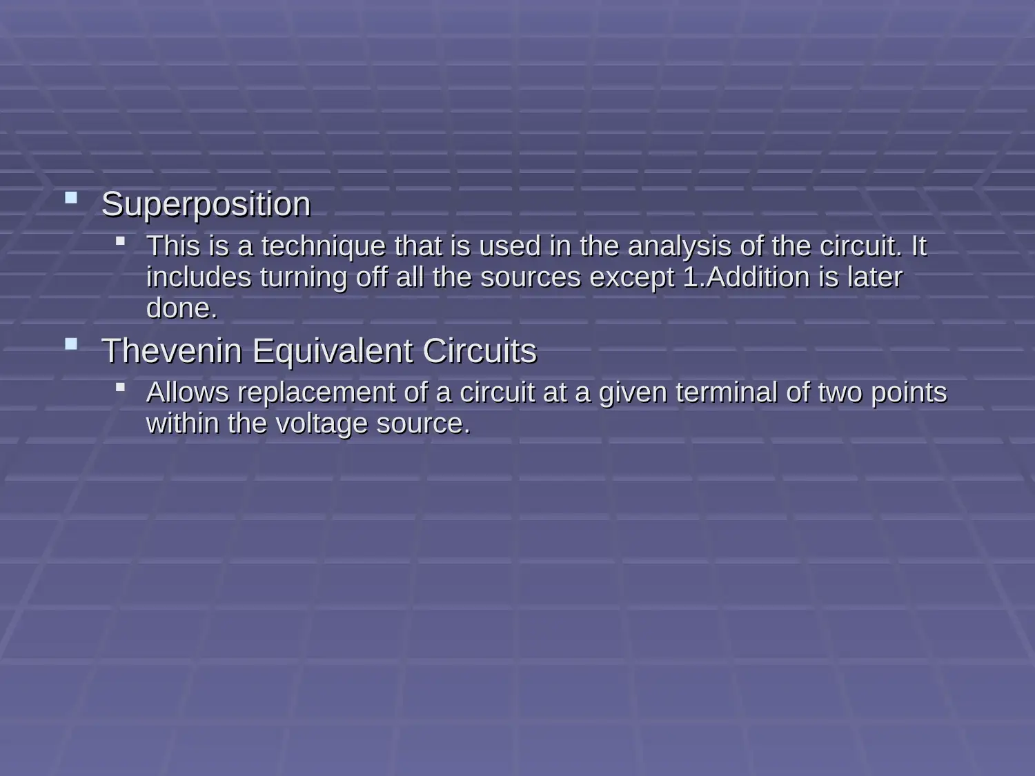
SuperpositionSuperposition
This is a technique that is used in the analysis of the circuit. ItThis is a technique that is used in the analysis of the circuit. It
includes turning off all the sources except 1.Addition is laterincludes turning off all the sources except 1.Addition is later
done.done.
Thevenin Equivalent CircuitsThevenin Equivalent Circuits
Allows replacement of a circuit at a given terminal of two pointsAllows replacement of a circuit at a given terminal of two points
within the voltage source.within the voltage source.
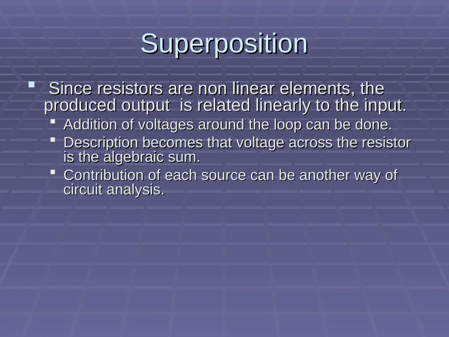
SuperpositionSuperposition
Since resistors are non linear elements, theSince resistors are non linear elements, the
produced output is related linearly to the input.produced output is related linearly to the input.
Addition of voltages around the loop can be done.Addition of voltages around the loop can be done.
Description becomes that voltage across the resistorDescription becomes that voltage across the resistor
is the algebraic sum.is the algebraic sum.
Contribution of each source can be another way ofContribution of each source can be another way of
circuit analysis.circuit analysis.
Secure Best Marks with AI Grader
Need help grading? Try our AI Grader for instant feedback on your assignments.
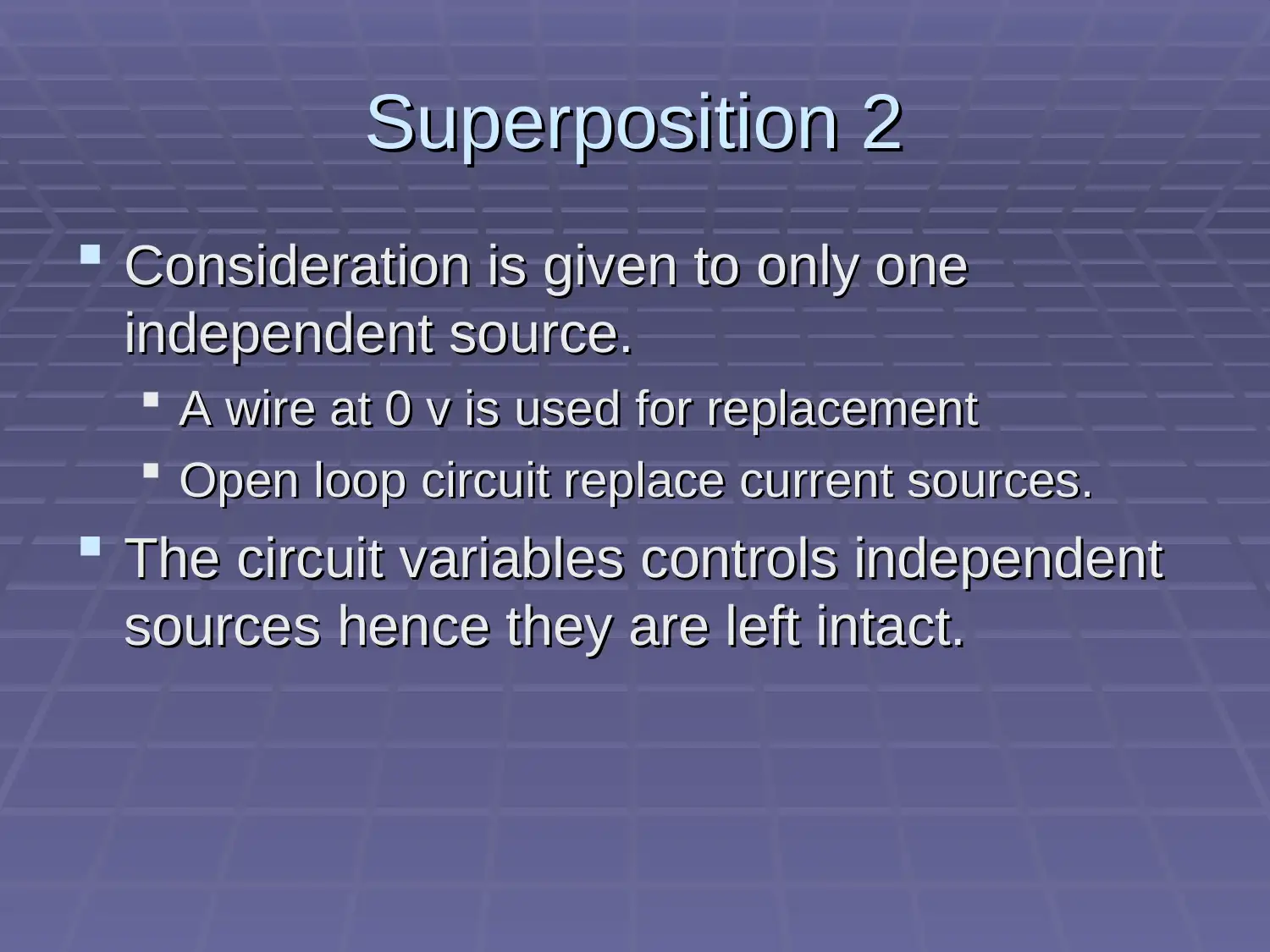
Superposition 2Superposition 2
Consideration is given to only oneConsideration is given to only one
independent source.independent source.
A wire at 0 v is used for replacementA wire at 0 v is used for replacement
Open loop circuit replace current sources.Open loop circuit replace current sources.
The circuit variables controls independentThe circuit variables controls independent
sources hence they are left intact.sources hence they are left intact.
Superposition 3Superposition 3
In order to solve any circuit usingIn order to solve any circuit using
superposing method, there is need ofsuperposing method, there is need of
repetition of independent sourcesrepetition of independent sources
.Algebraic sum will assist in getting the.Algebraic sum will assist in getting the
total voltage.total voltage.
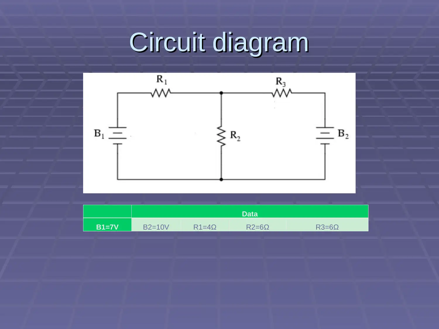
Circuit diagramCircuit diagram
Data
B1=7V B2=10V R1=4Ω R2=6Ω R3=6Ω
Data
B1=7V B2=10V R1=4Ω R2=6Ω R3=6Ω
Paraphrase This Document
Need a fresh take? Get an instant paraphrase of this document with our AI Paraphraser
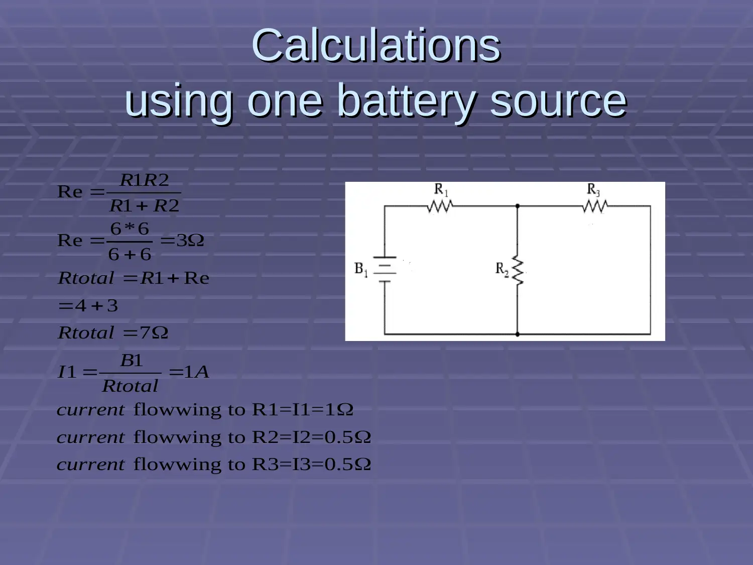
CalculationsCalculations
using one battery sourceusing one battery source
1 2
Re 1 2
6*6
Re 3
6 6
1 Re
4 3
7
1
1 1
flowwing to R1=I1=1
flowwing to R2=I2=0.5
flowwing to R3=I3=0.5
R R
R R
Rtotal R
Rtotal
B
I A
Rtotal
current
current
current
using one battery sourceusing one battery source
1 2
Re 1 2
6*6
Re 3
6 6
1 Re
4 3
7
1
1 1
flowwing to R1=I1=1
flowwing to R2=I2=0.5
flowwing to R3=I3=0.5
R R
R R
Rtotal R
Rtotal
B
I A
Rtotal
current
current
current
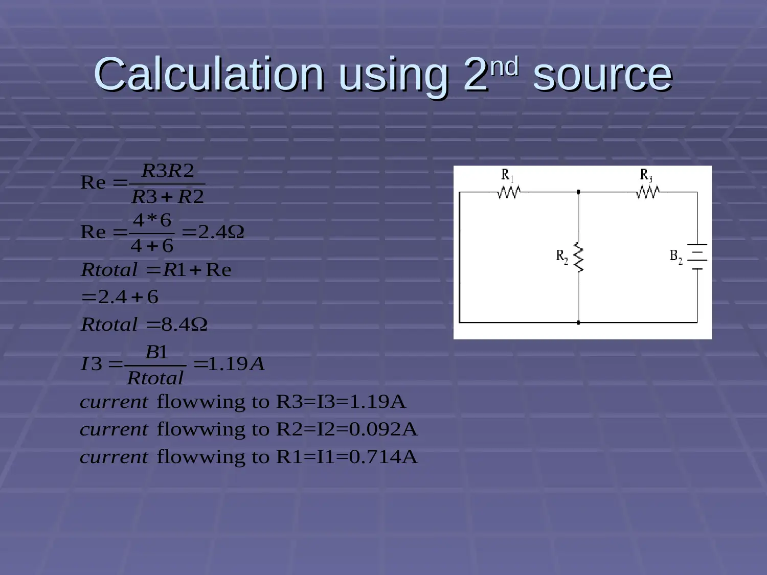
Calculation using 2Calculation using 2ndnd sourcesource
3 2
Re 3 2
4*6
Re 2.4
4 6
1 Re
2.4 6
8.4
1
3 1.19
flowwing to R3=I3=1.19A
flowwing to R2=I2=0.092A
flowwing to R1=I1=0.714A
R R
R R
Rtotal R
Rtotal
B
I A
Rtotal
current
current
current
3 2
Re 3 2
4*6
Re 2.4
4 6
1 Re
2.4 6
8.4
1
3 1.19
flowwing to R3=I3=1.19A
flowwing to R2=I2=0.092A
flowwing to R1=I1=0.714A
R R
R R
Rtotal R
Rtotal
B
I A
Rtotal
current
current
current
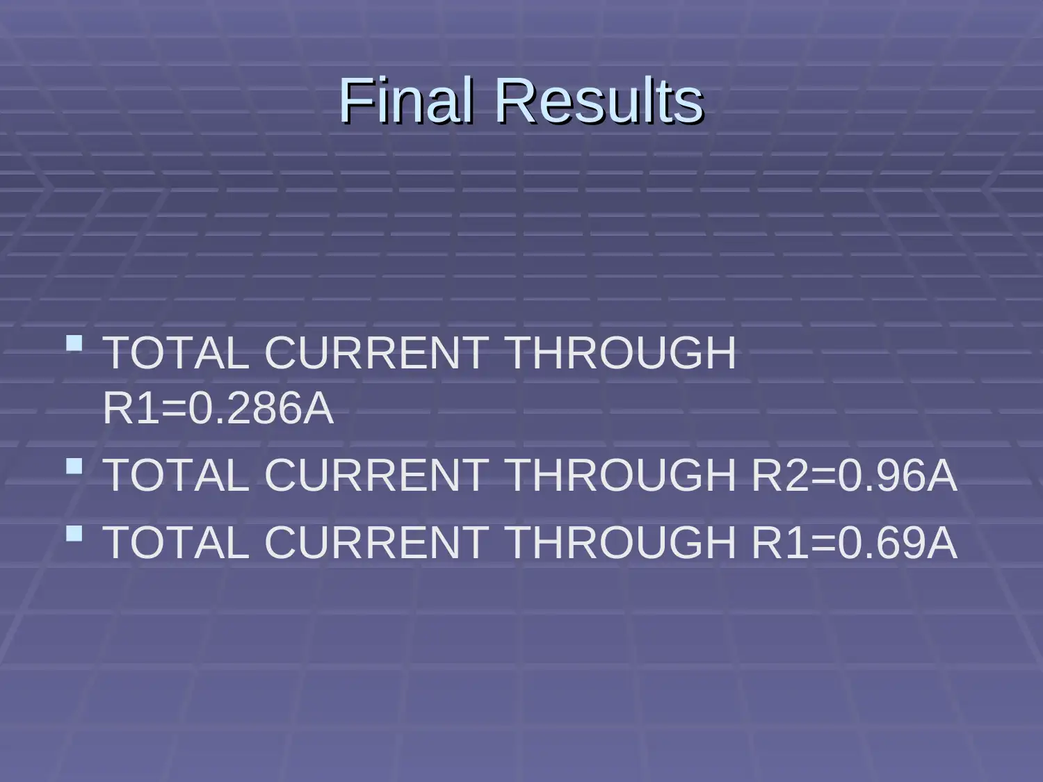
Final ResultsFinal Results
TOTAL CURRENT THROUGH
R1=0.286A
TOTAL CURRENT THROUGH R2=0.96A
TOTAL CURRENT THROUGH R1=0.69A
TOTAL CURRENT THROUGH
R1=0.286A
TOTAL CURRENT THROUGH R2=0.96A
TOTAL CURRENT THROUGH R1=0.69A
Secure Best Marks with AI Grader
Need help grading? Try our AI Grader for instant feedback on your assignments.
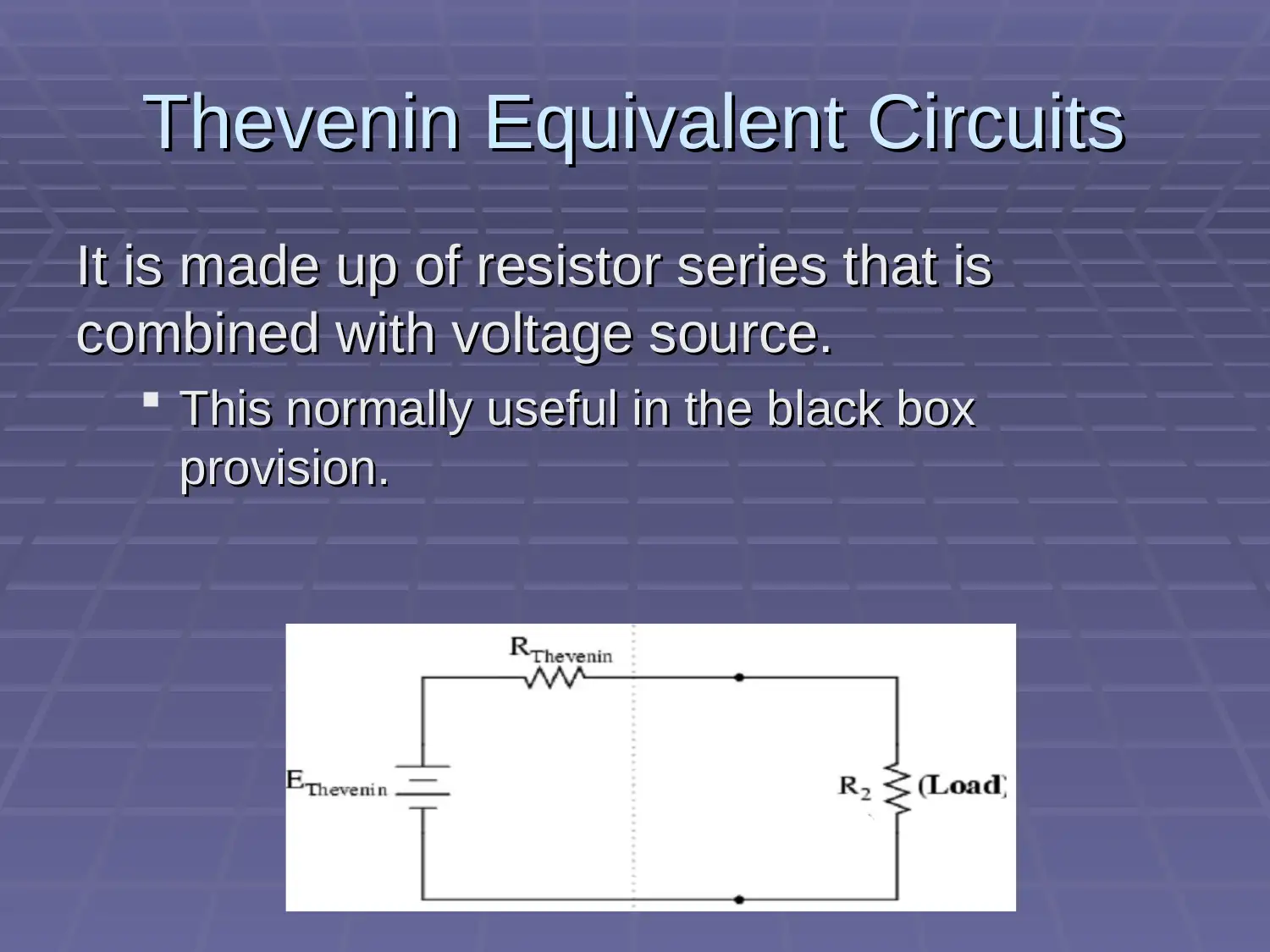
Thevenin Equivalent CircuitsThevenin Equivalent Circuits
It is made up of resistor series that isIt is made up of resistor series that is
combined with voltage source.combined with voltage source.
This normally useful in the black boxThis normally useful in the black box
provision.provision.
It is made up of resistor series that isIt is made up of resistor series that is
combined with voltage source.combined with voltage source.
This normally useful in the black boxThis normally useful in the black box
provision.provision.
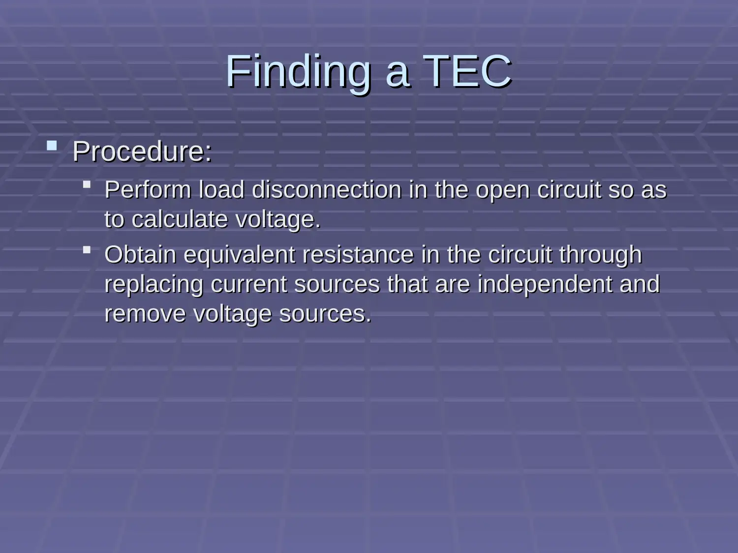
Finding a TECFinding a TEC
Procedure:Procedure:
Perform load disconnection in the open circuit so asPerform load disconnection in the open circuit so as
to calculate voltage.to calculate voltage.
Obtain equivalent resistance in the circuit throughObtain equivalent resistance in the circuit through
replacing current sources that are independent andreplacing current sources that are independent and
remove voltage sources.remove voltage sources.
calculationscalculations
2 1
=10-7=3V
R1 and R3 are parallel to each other
so their Equilance Resistatance will be Equal to
3 1
Re 2.4
3 1
0.8 V
placing it in the above circuit dia
Ethevwnon B B
Now
R R
R R
Ethevenon
By
gram
.8
Ithevenon= 0.095
2.4
is the total current that flow through
load resistance and is equal to.095A
Ethevenon A
Rthevenon Rload
Ithevenon
Paraphrase This Document
Need a fresh take? Get an instant paraphrase of this document with our AI Paraphraser
How complex wave are produce from sinusoidal waveform in
common electrical devices like iron cored inductor, switching
transformer
Creation of complex waveforms is by use of electrical
gadgets
A good example is in the cases of exchanging
transformers with inductive loads.
The result obtained is that the current wave form may
not be sinusoidal.
common electrical devices like iron cored inductor, switching
transformer
Creation of complex waveforms is by use of electrical
gadgets
A good example is in the cases of exchanging
transformers with inductive loads.
The result obtained is that the current wave form may
not be sinusoidal.
RLC series CircuitRLC series Circuit
There is normally a restriction in the game plan
of RLC.This affect capacitance and inductance
relationship.
The three fundamental standoff are obtained
here.This include the following:
Capacitance ,Inductance and resistance.
There is normally a restriction in the game plan
of RLC.This affect capacitance and inductance
relationship.
The three fundamental standoff are obtained
here.This include the following:
Capacitance ,Inductance and resistance.
RLC series circuitRLC series circuit
The Phase Difference, Φ is dependent on
the estimation of responsive parts being
used. The reactance will definitely be zero.
This because part of the circuit is resistive.
Variation of the circuit segment is from
positive to negative.
The Phase Difference, Φ is dependent on
the estimation of responsive parts being
used. The reactance will definitely be zero.
This because part of the circuit is resistive.
Variation of the circuit segment is from
positive to negative.
Secure Best Marks with AI Grader
Need help grading? Try our AI Grader for instant feedback on your assignments.
RLC series circuitRLC series circuit
The total confinement of a flood of current
is referred to as the impedance of a circuit.
The drawing of the triangle for impedance
for any RLC plan is achieved through side
isolation.
The total confinement of a flood of current
is referred to as the impedance of a circuit.
The drawing of the triangle for impedance
for any RLC plan is achieved through side
isolation.
RLC series circuitRLC series circuit
The voltage drop over the resistive
segment can be compared with the
formula ,I*R.In responsive parts ;I*X = I*XL
– I*XC .This gives a proportionate voltage
source. The obtained edge will be 0.
The voltage drop over the resistive
segment can be compared with the
formula ,I*R.In responsive parts ;I*X = I*XL
– I*XC .This gives a proportionate voltage
source. The obtained edge will be 0.
RLC series circuitRLC series circuit
Paraphrase This Document
Need a fresh take? Get an instant paraphrase of this document with our AI Paraphraser
RLC series circuitRLC series circuit
2 2 2 2
2 2*3.14*50*0.5 157
1 1 3.18 5
2 2*3.14*50*100
Impedance
Z= (XL XC) 14 (157 3.18 5) 157.62
10 0.063
157.62
* 0.888
* 9.96
* 2 6
XL fL
XC E
fC
Circuit
R E
Vs
I A
Z
VR I R V
VL I XL V
VC I XC E V
2 2 2 2
2 2*3.14*50*0.5 157
1 1 3.18 5
2 2*3.14*50*100
Impedance
Z= (XL XC) 14 (157 3.18 5) 157.62
10 0.063
157.62
* 0.888
* 9.96
* 2 6
XL fL
XC E
fC
Circuit
R E
Vs
I A
Z
VR I R V
VL I XL V
VC I XC E V
SI units Conversion
9
9
1. 0.260kilopascal to pascal
.260 1000=260 pascal
2. 0.976gram to nanogram
.976 10 976000000
10
3. 2.65 gigaliter to megaliter
2.65 1000=2650megaliter
4. 94.6 microliter to
nanogram
6
12
liter
94.6 10 =9.46E-5liter
5. 145femtometerto millimeter
145 10 =1.45E-10 milimeter
9
9
1. 0.260kilopascal to pascal
.260 1000=260 pascal
2. 0.976gram to nanogram
.976 10 976000000
10
3. 2.65 gigaliter to megaliter
2.65 1000=2650megaliter
4. 94.6 microliter to
nanogram
6
12
liter
94.6 10 =9.46E-5liter
5. 145femtometerto millimeter
145 10 =1.45E-10 milimeter
ReferenceReference
[1] R. Feynman and O. To, “RLC Circuits,” pp. 1–6, 1988.
[2] T. G. Solution, “The RLC Circuit,” pp. 1–2, 2001.
[3] R. Circuits and R. Circuits, “R-L-C Circuits and Resonant Circuits,”
pp. 1–9.
[4] S. Liao, P. Dourmashkin, and J. Belcher, “Chapter 12 Alternating-
Current Circuits,” Web.Mit.Edu, pp. 1–41, 2004.
[5] B. Leads and R. Leads, “Experiment 10 ~ RLC Series circuit,” pp.
1–4.
[6] R. F. Mould, “Chapter 13,” pp. 203–206, 2000.
[7] “Chapter 21 : RLC Circuits Voltage and Current in RLC Circuits,”
pp. 1–33.
Secure Best Marks with AI Grader
Need help grading? Try our AI Grader for instant feedback on your assignments.
1 out of 23
Related Documents
Your All-in-One AI-Powered Toolkit for Academic Success.
+13062052269
info@desklib.com
Available 24*7 on WhatsApp / Email
Unlock your academic potential
© 2024 | Zucol Services PVT LTD | All rights reserved.