Materials Engineering: Analysis of Factors Affecting Product Life
VerifiedAdded on 2023/06/12
|17
|3437
|115
Report
AI Summary
This report delves into various aspects of materials engineering, focusing on product service life. It examines the safe working life of a 212A42 steel pressure vessel under specific conditions, utilizing S-N curves and fatigue analysis to determine the number of cycles to failure. The report further investigates the impact of increased stress on product life, highlighting the role of plastic strain amplitude and creep. The interrelationship between stress, temperature, and lifetime vectors is explored, emphasizing their combined effect on thermal stress and structural integrity. Furthermore, the report analyzes the engineering causes of the 1985 Manchester airport flight crash, focusing on material failure and subsequent recommendations. Finally, it discusses the history and technical details of the 1934 class steam locomotive, pinpointing factors contributing to crank axle fatigue failures, and the role of torque wrenches in prolonging product service life and reducing scrap in engineering assembly.

Materials Engineering
Name
Institution
Name
Institution
Paraphrase This Document
Need a fresh take? Get an instant paraphrase of this document with our AI Paraphraser
Materials Engineering
1. An 212A42 steel is to be used to manufacture pressure vessel capable of storing
superheated steam at a temperature of 700֯ C and at a stress of 30MPa. Using the attached
chart, determine the safe working life of the vessel. Some approximation will be
necessary.
To establish if there is material failure in a pressure vessel, the common methodologies used
include complete scientific methods that utilize a simulation of numerical figures in order to
establish any causes of failure of the pressure vessel such as the use of finite element analysis or
to utilize the s-N curve to derive the service life of the pressure vessel. Typically, the pressure
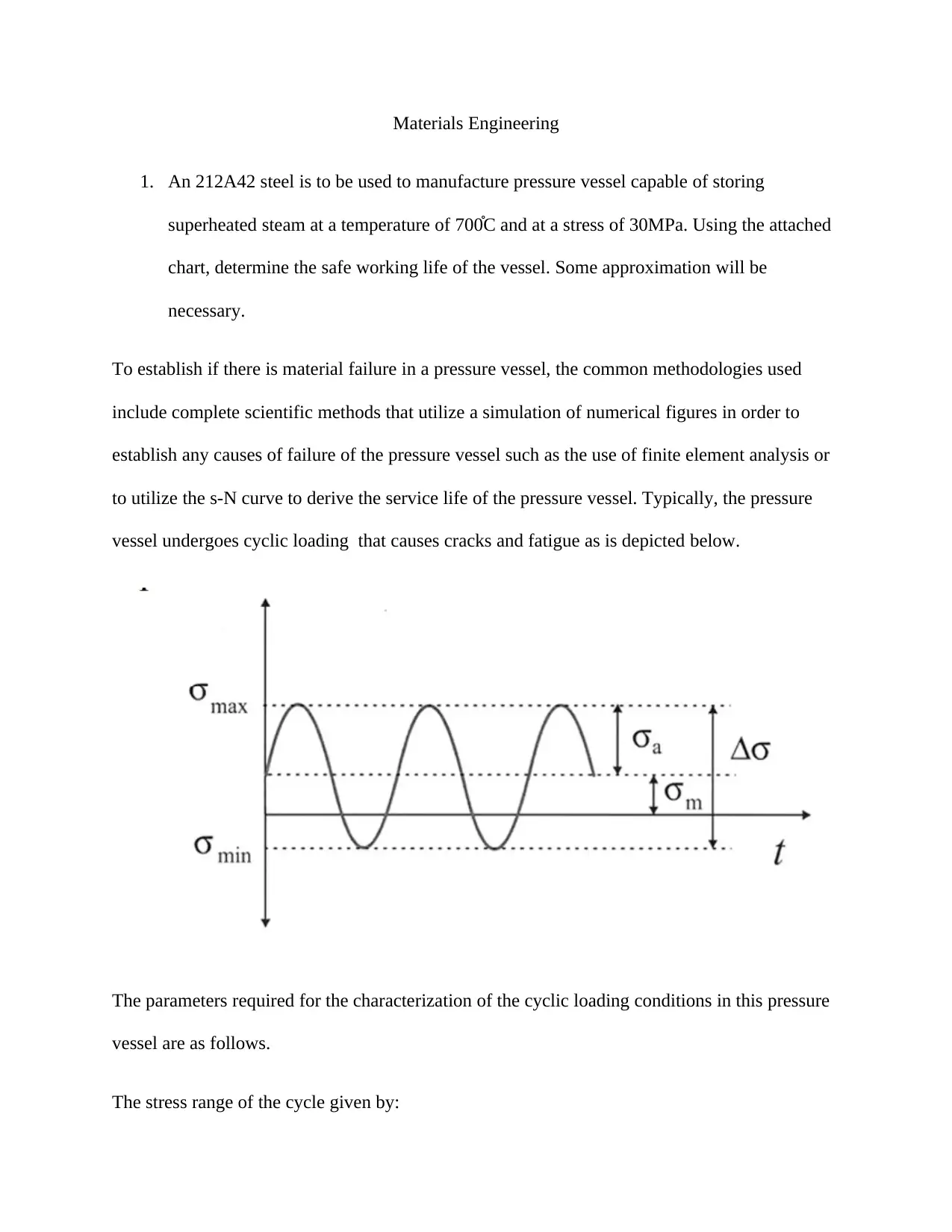
vessel undergoes cyclic loading that causes cracks and fatigue as is depicted below.
The parameters required for the characterization of the cyclic loading conditions in this pressure
vessel are as follows.
The stress range of the cycle given by:
∆ σ=σmax−σmin
For this case:
∆ σ=30−−30=60 MPa
Stress amplitude of the cycles given by:
σ a= 1
2 ( σmax−σ min)
σ a= 1
2 ( 30−−30 )=30 Mpa
Mean stress of the cycles
σ m= 1
2 (σmax+ σmin)
σ m= 1
2 ( 30 ±30 )=0
Load ratio of the cycles
R= σ min
σ max
R=−30
30 =−1
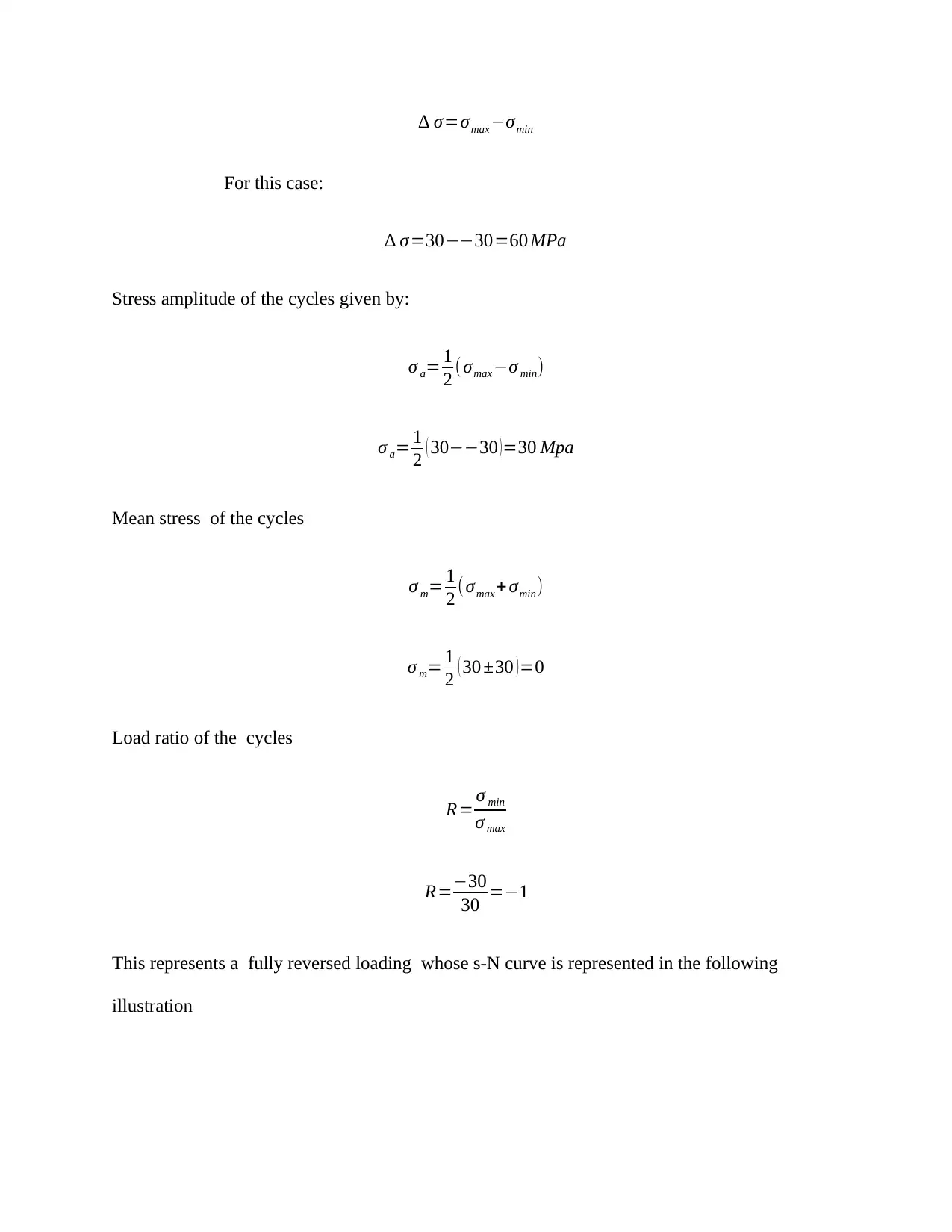
This represents a fully reversed loading whose s-N curve is represented in the following
illustration
⊘ This is a preview!⊘
Do you want full access?
Subscribe today to unlock all pages.

Trusted by 1+ million students worldwide
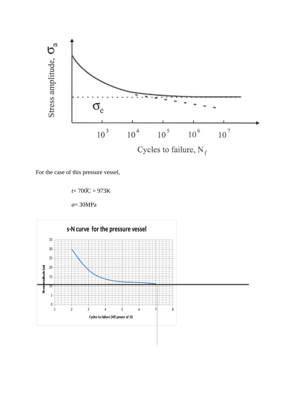
For the case of this pressure vessel,
t= 700֯ C = 973K
σ= 30MPa
1 2 3 4 5 6 7 8
0
5
10
15
20
25
30
35
s-N curve for the pressure vessel
Cycles to failure (Nf) power of 10
Stress amplitude (σa)
t= 700֯ C = 973K
σ= 30MPa
1 2 3 4 5 6 7 8
0
5
10
15
20
25
30
35
s-N curve for the pressure vessel
Cycles to failure (Nf) power of 10
Stress amplitude (σa)
Paraphrase This Document
Need a fresh take? Get an instant paraphrase of this document with our AI Paraphraser
The endurance limit in this graph can be taken as that received at Nf =stress amplitude at 107
Thus the endurance limit for this graph is 11.25Mpa
To establish the fatigue life of the pressure vessel, plotting a graph of log σa against log of 2Nf
(because one cycle takes 2 reversals) yields the following equation
σ a=σ f
' (2 Nf )b
Where σ f
' is the true fracture strength of the steel 212A42 which is 465N/mm2 (Mpa)
And b is the fatigue strength exponent, assumed to be -0.12
30=465(2 Nf )−0.12
2 Nf is the number of cycles = 8.3065*109 cycles
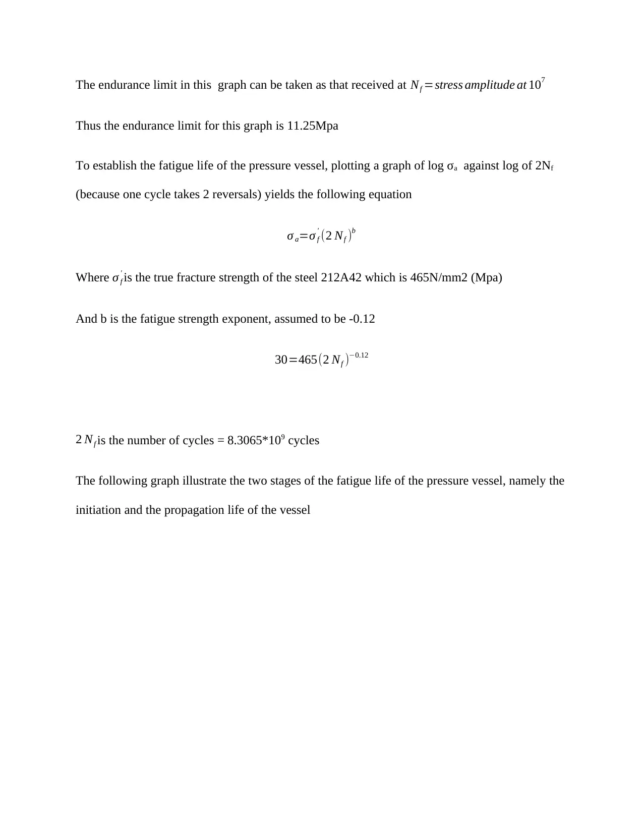
The following graph illustrate the two stages of the fatigue life of the pressure vessel, namely the
initiation and the propagation life of the vessel
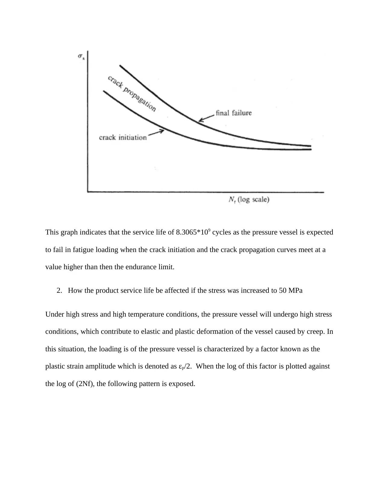
This graph indicates that the service life of 8.3065*109 cycles as the pressure vessel is expected
to fail in fatigue loading when the crack initiation and the crack propagation curves meet at a
value higher than then the endurance limit.
2. How the product service life be affected if the stress was increased to 50 MPa
Under high stress and high temperature conditions, the pressure vessel will undergo high stress
conditions, which contribute to elastic and plastic deformation of the vessel caused by creep. In
this situation, the loading is of the pressure vessel is characterized by a factor known as the
plastic strain amplitude which is denoted as εp/2. When the log of this factor is plotted against
the log of (2Nf), the following pattern is exposed.
⊘ This is a preview!⊘
Do you want full access?
Subscribe today to unlock all pages.

Trusted by 1+ million students worldwide
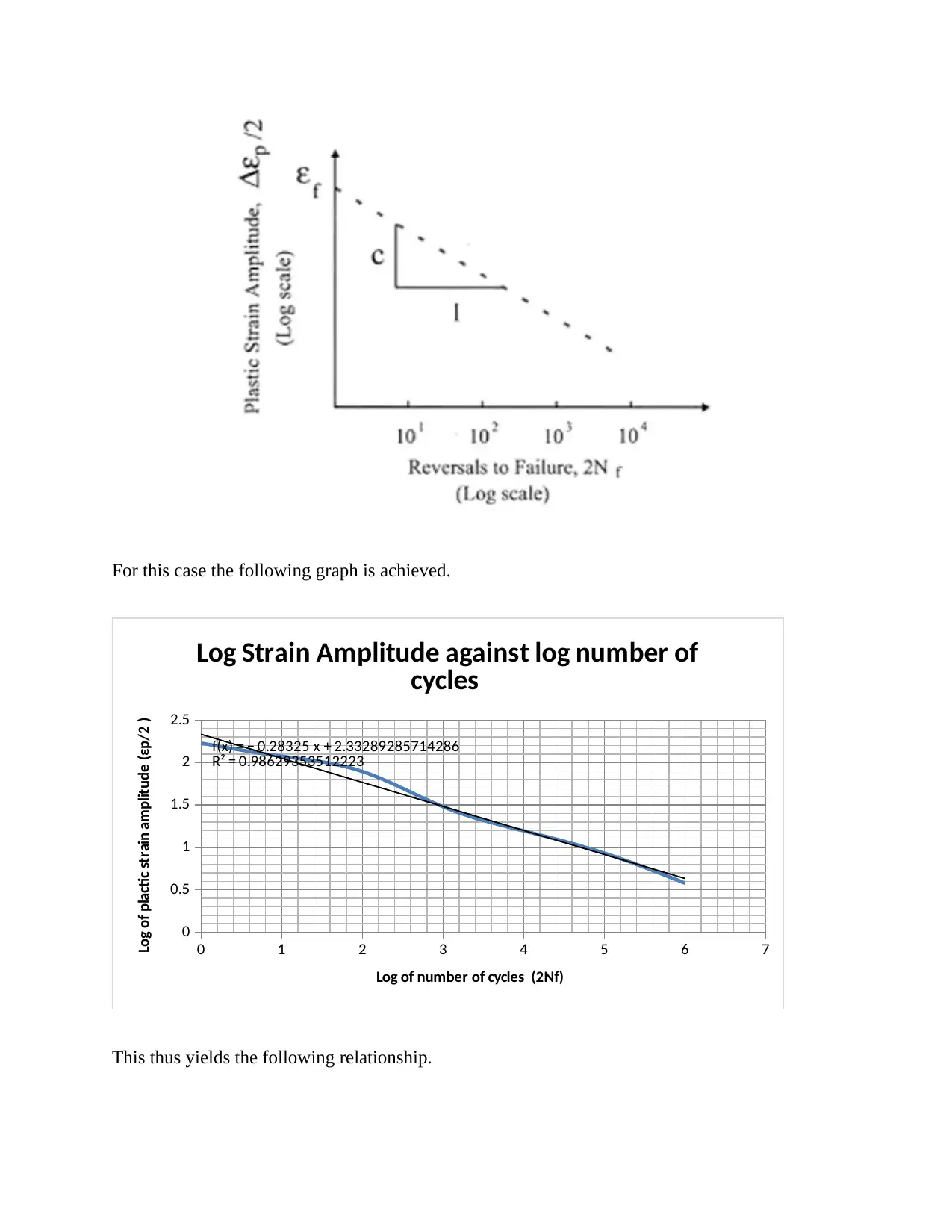
For this case the following graph is achieved.
0 1 2 3 4 5 6 7
0
0.5
1
1.5
2
2.5
f(x) = − 0.28325 x + 2.33289285714286
R² = 0.98629353512223
Log Strain Amplitude against log number of
cycles
Log of number of cycles (2Nf)
Log of plactic strain amplitude (εp/2 )
This thus yields the following relationship.
0 1 2 3 4 5 6 7
0
0.5
1
1.5
2
2.5
f(x) = − 0.28325 x + 2.33289285714286
R² = 0.98629353512223
Log Strain Amplitude against log number of
cycles
Log of number of cycles (2Nf)
Log of plactic strain amplitude (εp/2 )
This thus yields the following relationship.
Paraphrase This Document
Need a fresh take? Get an instant paraphrase of this document with our AI Paraphraser
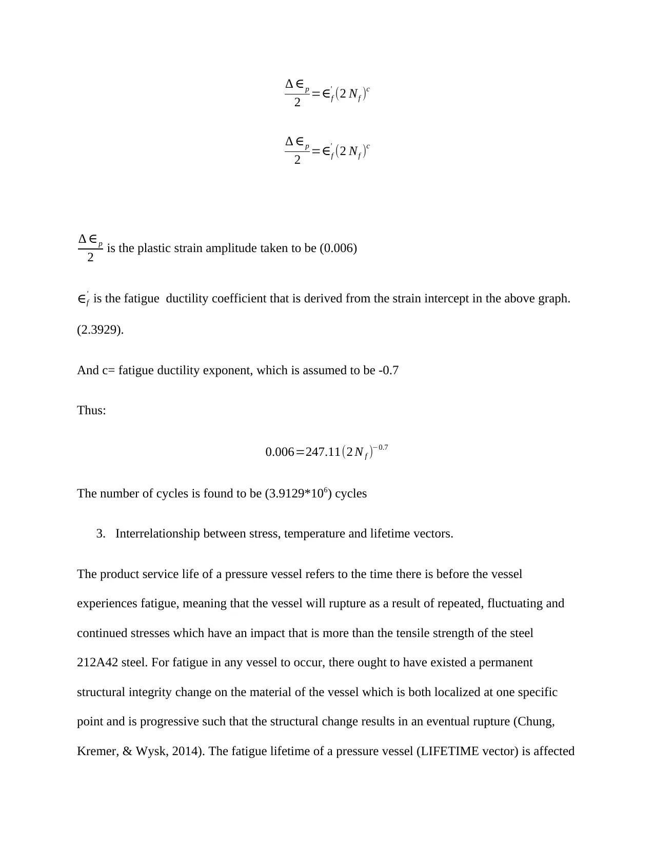
∆ ∈p
2 =∈f
' (2 Nf )c
∆ ∈p
2 =∈f
' (2 Nf )c
∆ ∈p
2 is the plastic strain amplitude taken to be (0.006)
∈f
' is the fatigue ductility coefficient that is derived from the strain intercept in the above graph.
(2.3929).
And c= fatigue ductility exponent, which is assumed to be -0.7
Thus:
0.006=247.11(2 N f )−0.7
The number of cycles is found to be (3.9129*106) cycles
3. Interrelationship between stress, temperature and lifetime vectors.
The product service life of a pressure vessel refers to the time there is before the vessel
experiences fatigue, meaning that the vessel will rupture as a result of repeated, fluctuating and
continued stresses which have an impact that is more than the tensile strength of the steel
212A42 steel. For fatigue in any vessel to occur, there ought to have existed a permanent
structural integrity change on the material of the vessel which is both localized at one specific
point and is progressive such that the structural change results in an eventual rupture (Chung,
Kremer, & Wysk, 2014). The fatigue lifetime of a pressure vessel (LIFETIME vector) is affected
2 =∈f
' (2 Nf )c
∆ ∈p
2 =∈f
' (2 Nf )c
∆ ∈p
2 is the plastic strain amplitude taken to be (0.006)
∈f
' is the fatigue ductility coefficient that is derived from the strain intercept in the above graph.
(2.3929).
And c= fatigue ductility exponent, which is assumed to be -0.7
Thus:
0.006=247.11(2 N f )−0.7
The number of cycles is found to be (3.9129*106) cycles
3. Interrelationship between stress, temperature and lifetime vectors.
The product service life of a pressure vessel refers to the time there is before the vessel
experiences fatigue, meaning that the vessel will rupture as a result of repeated, fluctuating and
continued stresses which have an impact that is more than the tensile strength of the steel
212A42 steel. For fatigue in any vessel to occur, there ought to have existed a permanent
structural integrity change on the material of the vessel which is both localized at one specific
point and is progressive such that the structural change results in an eventual rupture (Chung,
Kremer, & Wysk, 2014). The fatigue lifetime of a pressure vessel (LIFETIME vector) is affected
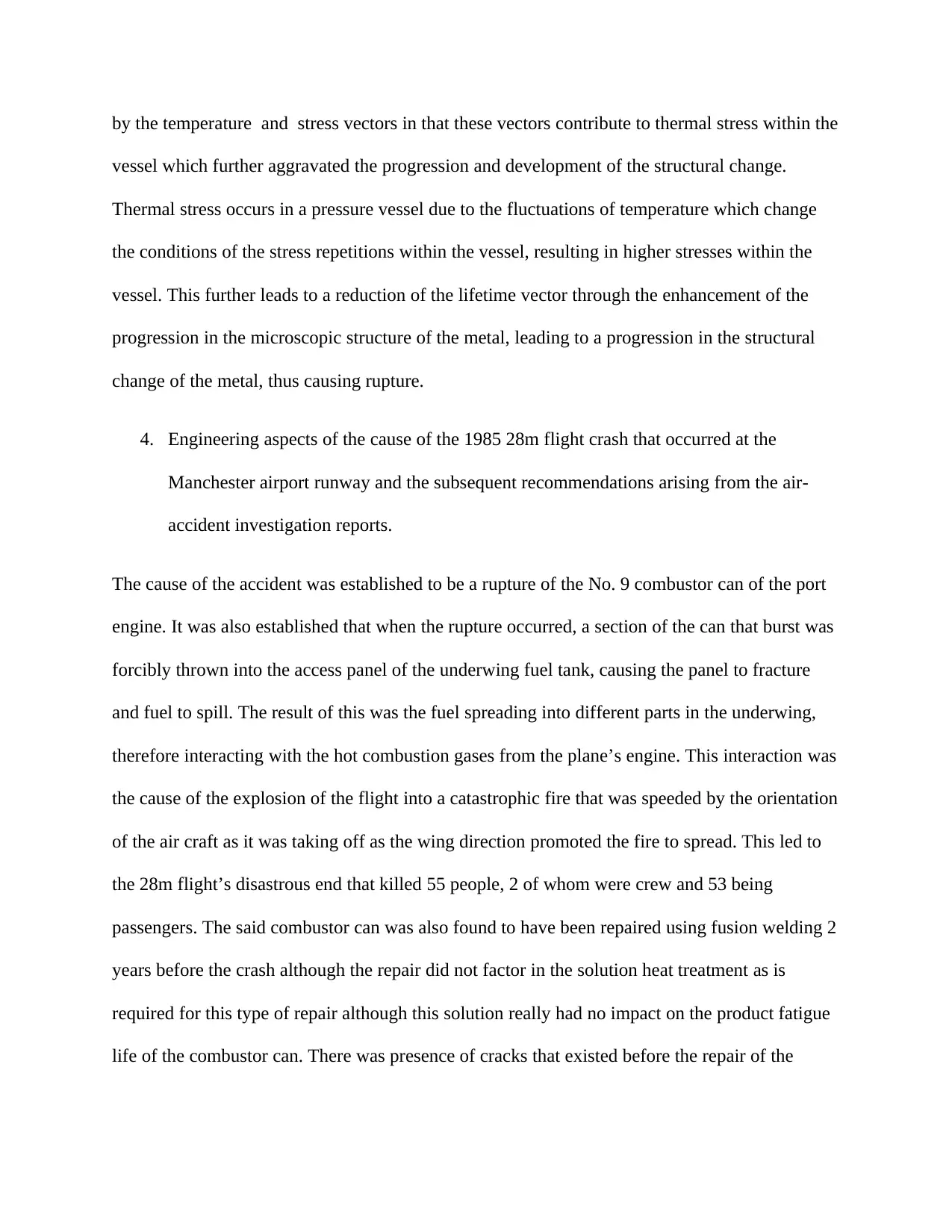
by the temperature and stress vectors in that these vectors contribute to thermal stress within the
vessel which further aggravated the progression and development of the structural change.
Thermal stress occurs in a pressure vessel due to the fluctuations of temperature which change
the conditions of the stress repetitions within the vessel, resulting in higher stresses within the
vessel. This further leads to a reduction of the lifetime vector through the enhancement of the
progression in the microscopic structure of the metal, leading to a progression in the structural
change of the metal, thus causing rupture.
4. Engineering aspects of the cause of the 1985 28m flight crash that occurred at the
Manchester airport runway and the subsequent recommendations arising from the air-
accident investigation reports.
The cause of the accident was established to be a rupture of the No. 9 combustor can of the port
engine. It was also established that when the rupture occurred, a section of the can that burst was
forcibly thrown into the access panel of the underwing fuel tank, causing the panel to fracture
and fuel to spill. The result of this was the fuel spreading into different parts in the underwing,
therefore interacting with the hot combustion gases from the plane’s engine. This interaction was
the cause of the explosion of the flight into a catastrophic fire that was speeded by the orientation
of the air craft as it was taking off as the wing direction promoted the fire to spread. This led to
the 28m flight’s disastrous end that killed 55 people, 2 of whom were crew and 53 being
passengers. The said combustor can was also found to have been repaired using fusion welding 2
years before the crash although the repair did not factor in the solution heat treatment as is
required for this type of repair although this solution really had no impact on the product fatigue
life of the combustor can. There was presence of cracks that existed before the repair of the
⊘ This is a preview!⊘
Do you want full access?
Subscribe today to unlock all pages.

Trusted by 1+ million students worldwide
combustor can, although the investigations about creep and fatigue loading were derailed by the
damages caused by the fire that resulted in the incident (Alarifi, Phylatou, & Andrews, 2016).
Some of the recommendations arising from the investigation of this air accident included
implementing stringent policies and regulations about aircraft safety. It was established that the
fatalities of the 55 was as a result of the lack of any provision to fight any fires that occurred
inside the plane as well as the layout of the plane that limited the ability of those aboard to
evacuate. There was also an issue of the vulnerability of the tanks situated at the wings to impact
from other parts of the plane, such that the plane is unable to hull any fires that results from the
external parts of the plane, exposing those aboard to the dangers of the fire and the toxic
emissions that result from the burning of any interior materials of the plane. The layout of the
plane caused most of the passengers to be badly affected by smoke incapacitation and inhalation
of lethal gases. Planes thus ought to be fitted with oxygen masks and fire extinguishers in the
event of a fire to deal with internal fires. There were also procedures that were developed to
allow the plane to be positioned such that the fuselage is always downwind the fire. The cabin
materials were lso decided to be fire resistant to prevent the spread of fires. It also called for an
even distribution of cabin crew throughout the plane to ensure experienced individuals can help
those onboard in the event of a fire in any part of the plane (Melis, Silver, & Yeun, 2017).
5. History and technical details of the class steam locomotive of 1934 designed by Sir Nigel
Gresley and the factors that caused its crank axle fatigue failures
In 1934, Sir Nigel Gresley’s steam locomotives known as the P2s were known as an
innovative design that were able to haul heavy trains in long distances by combining the 2-8-2
wheel arrangement that made them powerful locomotives with a good outward aesthetic design.
Paraphrase This Document
Need a fresh take? Get an instant paraphrase of this document with our AI Paraphraser
The design was able to hide the boiler in an elliptical and parallel cladding running from the cab
to the smoke box with smoke deflectors. The boiler was 220lb/sq. in. to feed a three cylinders
that would emit a traction force of 43460 lb. Some of the famous P2s include the Cock o’ the
North, and the Earl Marischal that utilized smoke deflectors to enhance a softer exhaust. Others
were Lord President, Mons Meg, Thane of Fife, and Wolf of Badenoch. The steam locomotives
demonstrated some crank axle fatigue failures that were mainly caused by factors such as stress
and the design of the keyway that negatively impacted the product life of the crank axles used in
the locomotive. The incorporation of a stress relief grove and a better design of the keyway led to
a 60% improvement of fatigue failures (Nock, 2013).
Other design factors that led to this constant failure in the crank axle of these locomotives
included an unstable arrangement of the frames which contributed to an unstable foundation of
the engine. The frame in these locomotives characterized a leading pony truck that had
difficulties in steering the leading wheels, and thus causing big-ends to become heated and the
crank axle to become strained. Further, the running gears and the wheel set in the P2 locomotives
were casted and forged, leading to many uncommon patterns that would result in failures. The
valve gears installed were also rotary valve gears which would promote an increase in the boiler
pressure of the steam locomotives. This is because the option limited the cutoff settings of the
locomotives resulting in high energy consumption that would increase the temperature and thus
promote fatigue failures. The installed boilers were of 220 lb/sq. in. denying the option of
interchanging te boilers during an overhaul thus exposing the steam locomotive higher risks of
creep and fatigue lauding leading to failure. This was due to the fact that the low thermal
efficiency experienced in this breed of steam locomotives led to an increase in the stress it
experiences and thus a reduction of the fatigue life of the component. The weight carried by the
locomotives was double that of the tender applying up to 193.3 kN on the crank which ended up
failing a number of times. During braking, primary air brakes were used which were not as
effective. The high traction load increased the stress felt on the crack reducing the product
service life of the crank as was witnessed through the numerous failures (Wragg, 2017).
6. Torque-wrenches in product service life and reducing scrap in engineering assembly
Torque wrenches refer to tools used for tightening screws and bolts such that a specified
amount of torque is applied to the fasteners. The torque wrench is used for purposes of
prolonging service life of different engineering apparatus and vessels, in that it permits for the
measurement of the torque applied to the screw, nut, or bolt, so that it matches the specifications
for the given application. This ensures that tension is maintained and fatigue loading is avoided,
thus prolonging the service life of the said application. With regard to the reduction of scrap, it
guarantees that no product’s structural or static parameters are exceeded, thus guaranteeing that
no products integrity is compromised leading to its conversion to a scrap, and thus reducing the
generation of scrap in an engineering assembly. This is because products that are said to have
compromised integrity cannot be passed for finished products, and thus they are automatically
turned to scrap products (Xia, Lin, Yuan, Bai, & Zheng, 2014). For the general safety
functioning of a system, when the tension and loading within the system are balanced and at par
with their specification for its given application, the system remains safe as there are no risks of
excess or imbalanced tensions that contribute to unwanted loading conditions that could cause
fatigue and creep failures in rapture. This rapture could have impacts that compromise the safety
of the system in this manner, and thus the use of a torques wrench in this manner would
contribute to the safe functioning of a given system (Gehrke, et al, 2016).
⊘ This is a preview!⊘
Do you want full access?
Subscribe today to unlock all pages.

Trusted by 1+ million students worldwide
1 out of 17
Related Documents
Your All-in-One AI-Powered Toolkit for Academic Success.
+13062052269
info@desklib.com
Available 24*7 on WhatsApp / Email
![[object Object]](/_next/static/media/star-bottom.7253800d.svg)
Unlock your academic potential
Copyright © 2020–2026 A2Z Services. All Rights Reserved. Developed and managed by ZUCOL.


