Materials Engineering Laboratory: Tensile Testing Analysis and Report
VerifiedAdded on 2022/09/13
|9
|1330
|21
Practical Assignment
AI Summary
This assignment is a comprehensive report on tensile testing experiments conducted on three different material samples. The introduction highlights the importance of tensile testing in ensuring the safety of structural components and describes the process of applying axial forces to a specimen until deformation and failure occur. The aims of the experiment were to understand the behavior of materials under tension, determine mechanical properties like Young's modulus, and draw conclusions about the material type. The results section presents tabular data of time, extension, load, stress, and strain for each sample, along with graphs illustrating the stress-strain curves. The discussion section analyzes the differences in extension rates, tensile strengths, and Young's modulus among the samples, linking these properties to the micro-crystalline structure of the materials. It also addresses experimental errors and provides conclusions regarding the applications of each material based on its tensile properties. The assignment also includes answers to questions related to Young’s Modulus and material behavior, and references relevant literature.
MATERIALS ENGINEERING
By Name
Course
Instructor
Institution
Location
Date
By Name
Course
Instructor
Institution
Location
Date
Paraphrase This Document
Need a fresh take? Get an instant paraphrase of this document with our AI Paraphraser
Introduction
The tensile features of materials need to be evaluated to ensure the safety during the design of
structural components including bridges, aircrafts, railways lines, pressure vessels, marine ships
among others. Therefore tensile strength of materials ought to meets the requirements of strength
of the specific structural application (Simonovski, Holmström & Bruchhausen, 2017). The
mechanical features of the metals determine the type of engineering application to be adopted.
Experiments involving tensile tests may be used in the prediction of the tensile features and they
are carried out by applying axial or even longitudinal forces on a given specimen whose
dimensions are known. Such forces are applied on the specimen to the point the specimen
undergoes deformation which then results in failure (Yarin, Lee, An & Yoon, 2019). The tensile
load alongside the corresponding extensions is thereafter noted for purposes of statistical analysis
besides determination of the strain-stress relationship of specimen of material used.
Aims
To comprehend behavior of various material under tension
To determine the various mechanical properties of metals
To draw conclusion regarding the type of material
To solicit theory on dislocation movement as well as strain hardening
To visualize the failure of a material under a microscope
Results
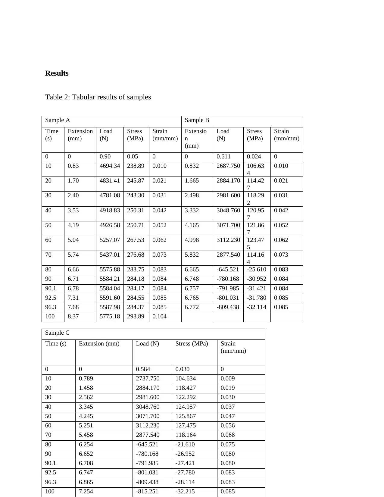
Table 2: Tabular results of samples
Sample A Sample B
Time
(s)
Extension
(mm)
Load
(N)
Stress
(MPa)
Strain
(mm/mm)
Extensio
n
(mm)
Load
(N)
Stress
(MPa)
Strain
(mm/mm)
0 0 0.90 0.05 0 0 0.611 0.024 0
10 0.83 4694.34 238.89 0.010 0.832 2687.750 106.63
4
0.010
20 1.70 4831.41 245.87 0.021 1.665 2884.170 114.42
7
0.021
30 2.40 4781.08 243.30 0.031 2.498 2981.600 118.29
2
0.031
40 3.53 4918.83 250.31 0.042 3.332 3048.760 120.95
7
0.042
50 4.19 4926.58 250.71 0.052 4.165 3071.700 121.86
7
0.052
60 5.04 5257.07 267.53 0.062 4.998 3112.230 123.47
5
0.062
70 5.74 5437.01 276.68 0.073 5.832 2877.540 114.16
4
0.073
80 6.66 5575.88 283.75 0.083 6.665 -645.521 -25.610 0.083
90 6.71 5584.21 284.18 0.084 6.748 -780.168 -30.952 0.084
90.1 6.78 5584.04 284.17 0.084 6.757 -791.985 -31.421 0.084
92.5 7.31 5591.60 284.55 0.085 6.765 -801.031 -31.780 0.085
96.3 7.68 5587.98 284.37 0.085 6.772 -809.438 -32.114 0.085
100 8.37 5775.18 293.89 0.104
Sample C
Time (s) Extension (mm) Load (N) Stress (MPa) Strain
(mm/mm)
0 0 0.584 0.030 0
10 0.789 2737.750 104.634 0.009
20 1.458 2884.170 118.427 0.019
30 2.562 2981.600 122.292 0.030
40 3.345 3048.760 124.957 0.037
50 4.245 3071.700 125.867 0.047
60 5.251 3112.230 127.475 0.056
70 5.458 2877.540 118.164 0.068
80 6.254 -645.521 -21.610 0.075
90 6.652 -780.168 -26.952 0.080
90.1 6.708 -791.985 -27.421 0.080
92.5 6.747 -801.031 -27.780 0.083
96.3 6.865 -809.438 -28.114 0.083
100 7.254 -815.251 -32.215 0.085
⊘ This is a preview!⊘
Do you want full access?
Subscribe today to unlock all pages.

Trusted by 1+ million students worldwide
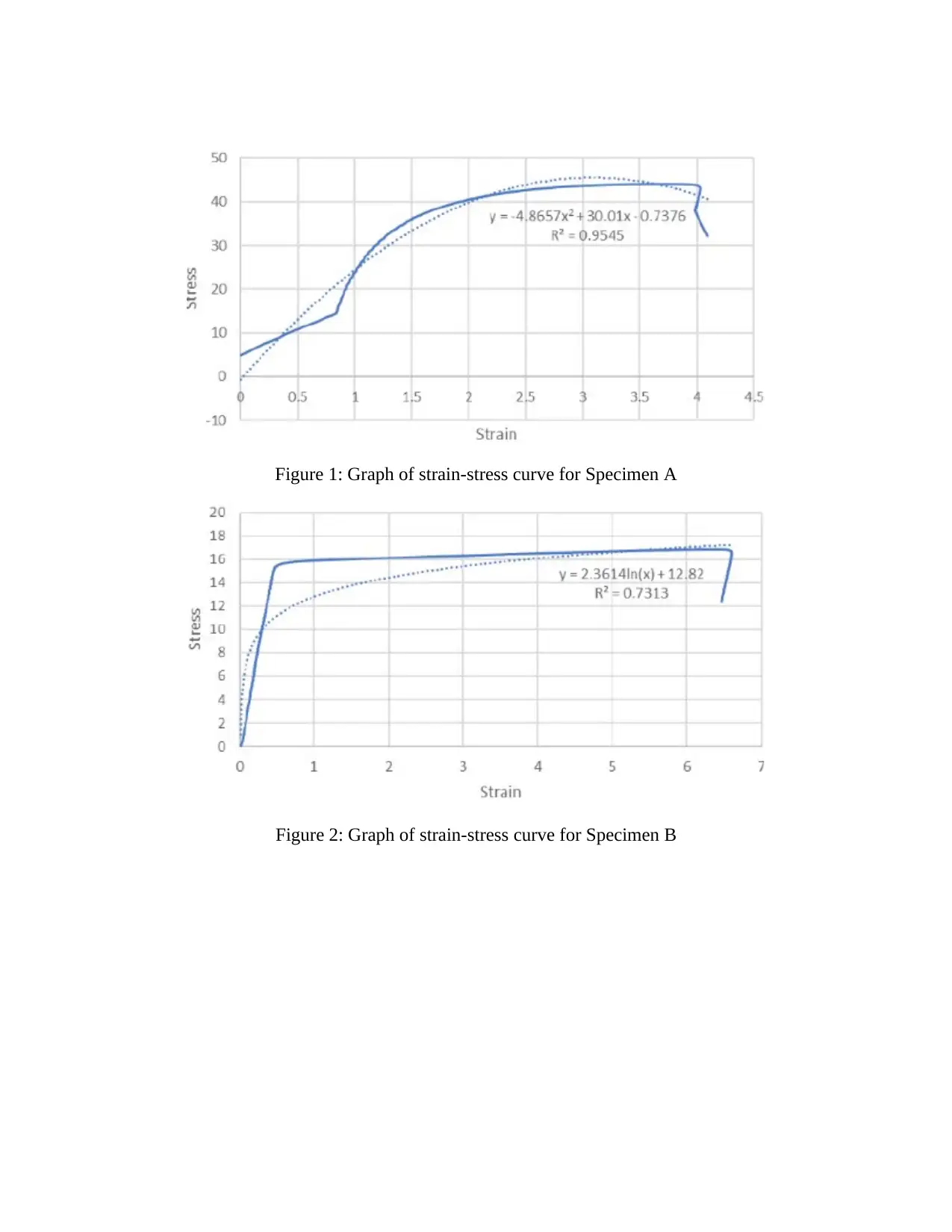
Figure 1: Graph of strain-stress curve for Specimen A
Figure 2: Graph of strain-stress curve for Specimen B
Figure 2: Graph of strain-stress curve for Specimen B
Paraphrase This Document
Need a fresh take? Get an instant paraphrase of this document with our AI Paraphraser
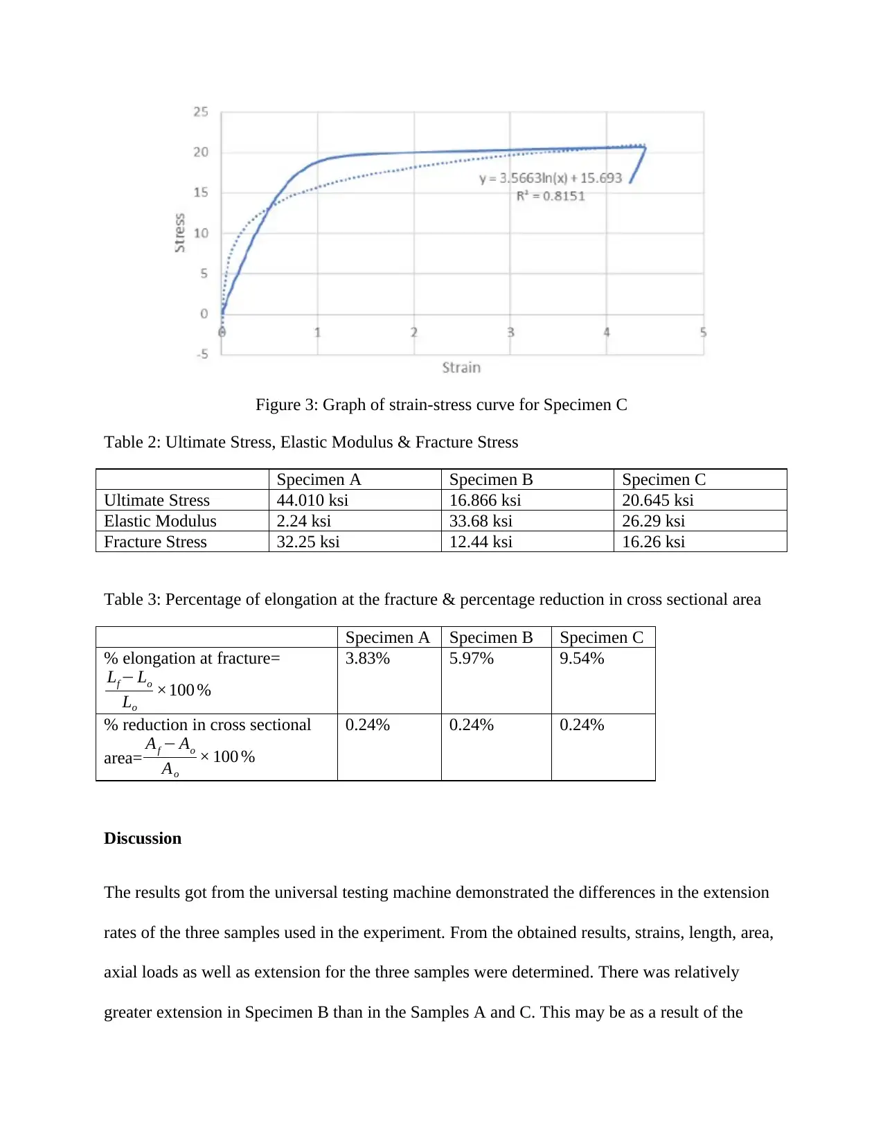
Figure 3: Graph of strain-stress curve for Specimen C
Table 2: Ultimate Stress, Elastic Modulus & Fracture Stress
Specimen A Specimen B Specimen C
Ultimate Stress 44.010 ksi 16.866 ksi 20.645 ksi
Elastic Modulus 2.24 ksi 33.68 ksi 26.29 ksi
Fracture Stress 32.25 ksi 12.44 ksi 16.26 ksi
Table 3: Percentage of elongation at the fracture & percentage reduction in cross sectional area
Specimen A Specimen B Specimen C
% elongation at fracture=
Lf − Lo
Lo
×100 %
3.83% 5.97% 9.54%
% reduction in cross sectional
area= Af − Ao
Ao
× 100 %
0.24% 0.24% 0.24%
Discussion
The results got from the universal testing machine demonstrated the differences in the extension
rates of the three samples used in the experiment. From the obtained results, strains, length, area,
axial loads as well as extension for the three samples were determined. There was relatively
greater extension in Specimen B than in the Samples A and C. This may be as a result of the
variations in the micro-crystalline structure of the three sample materials. Specimen A got to
yield point stress of 238 MPa, specimen B at 105 MPa and Specimen C at 235 MPa hence it is
notable that specimen A had the highest tensile strength in comparisons with specimen B and C
(Quercia, Chan & Luke, 2016).
Upon calculating the gradients of the three specimens, specimen A had the highest gradient of
the three specimens (Eftink, Cady & Saleh, 2018). The Young’s modulus is determined as the
gradient of the strain-stress curve which has an effect on the material deflection under various
loads. Loading the specimen further beyond the yield strength offered a stack difference where
the specimens fractured at various points. Variations in length show the ductility of the material
when under load. Great levels of necking were noted in specimen A than the remaining other two
specimen. The elongation of the specimen is hindered when specimen A and associated alloys
are subjected to precipitation hardening (Connelly, 2017).
Reliability and experimental errors
Some of the probable sources of error in the experiment involving tensile testing include
irregularities with the dimensions of the test specimen surface defects, loss of the fractured
particles as well as inaccurate insertion of the test specimens used (Zhou, Tagarielli, Heisserer &
Curtis, 2018).
Conclusion
Numerous applications in engineering that need high tensile strength often adopt materials that
bear such features. The experiment was successful as it was possible to gather data from every
specimen with the aid of the universal testing machines and thereafter interpretations of the data
in evaluating the Young’s modulus, ultimate stress, and extension/elongation among other
⊘ This is a preview!⊘
Do you want full access?
Subscribe today to unlock all pages.

Trusted by 1+ million students worldwide
studied features of engineering materials. There was consistence of the data of the three
specimens studied even though more testing was needed to enhance the levels of accuracy.
Answers to questions
1. Young’s Modulus is determined by the yield strength of a material
2. The elastic deflection will increase three times
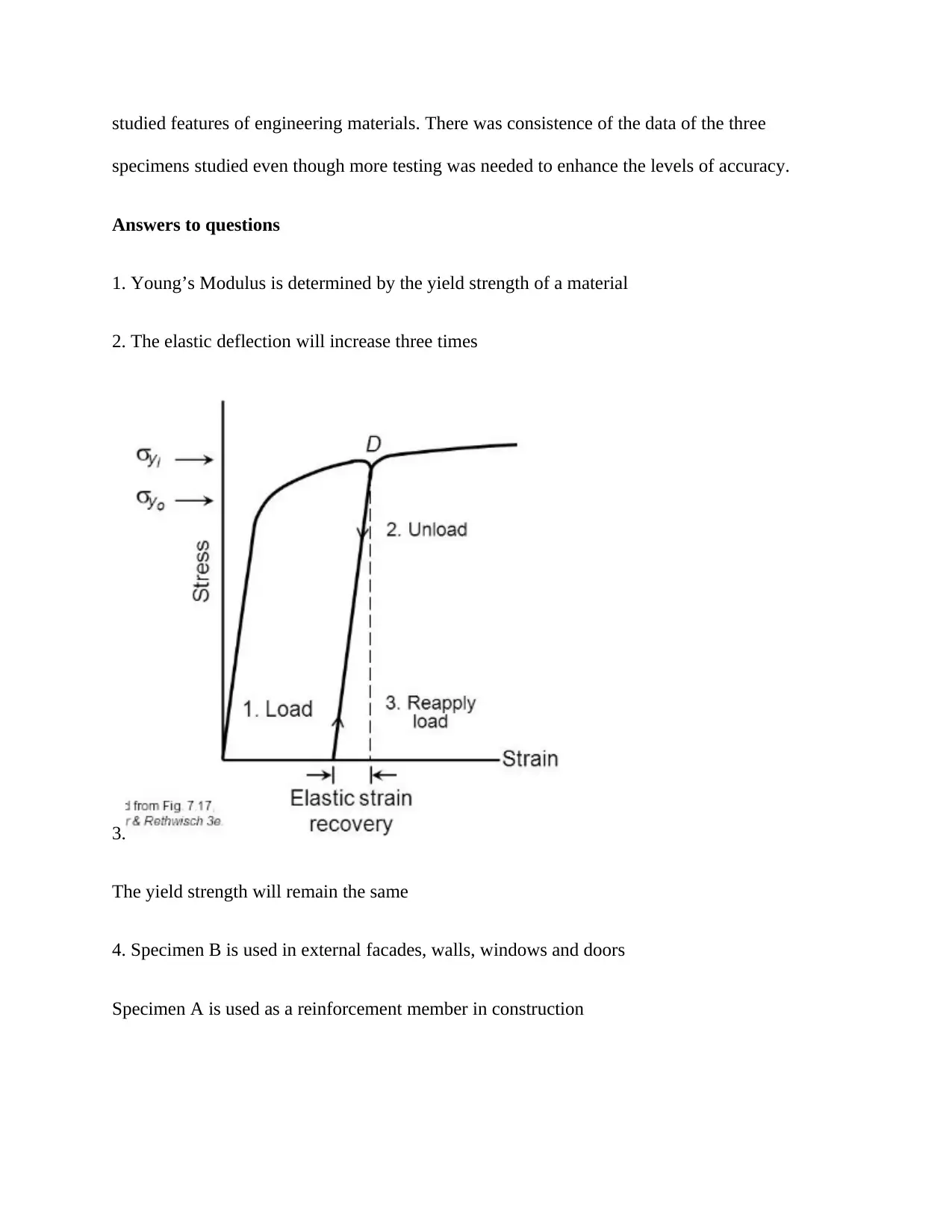
3.
The yield strength will remain the same
4. Specimen B is used in external facades, walls, windows and doors
Specimen A is used as a reinforcement member in construction
Paraphrase This Document
Need a fresh take? Get an instant paraphrase of this document with our AI Paraphraser

Specimen C is used in applications that need friction for instance locks, gears, rollers among
others
others
References
Connelly, K. (2017). 5 Common Errors in Tensile Testing. Quality, 56(11), 27-29
Eftink, B. P., Cady, C. M., & Saleh, T. A. (2018). Tensile Testing of Generation II FeCrAl
Tubing (No. LA-UR-18-28350). Los Alamos National Lab.(LANL), Los Alamos, NM
(United States)
Quercia, G., Chan, D., & Luke, K. (2016). Weibull statistics applied to tensile testing for oil well
cement compositions. Journal of Petroleum Science and Engineering, 146, 536-544
Simonovski, I., Holmström, S., & Bruchhausen, M. (2017). Small punch tensile testing of curved
specimens: Finite element analysis and experiment. International Journal of Mechanical
Sciences, 120, 204-213
Yarin, A. L., Lee, M. W., An, S., & Yoon, S. S. (2019). Self-Healing of Mechanical Properties:
Evaluation by Tensile Testing. In Self-Healing Nanotextured Vascular Engineering
Materials (pp. 165-194). Springer, Cham
Zhou, J., Tagarielli, V. L., Heisserer, U., & Curtis, P. T. (2018). An apparatus for tensile testing
of engineering materials. Experimental Mechanics, 58(6), 941-950
⊘ This is a preview!⊘
Do you want full access?
Subscribe today to unlock all pages.

Trusted by 1+ million students worldwide
1 out of 9
Your All-in-One AI-Powered Toolkit for Academic Success.
+13062052269
info@desklib.com
Available 24*7 on WhatsApp / Email
![[object Object]](/_next/static/media/star-bottom.7253800d.svg)
Unlock your academic potential
Copyright © 2020–2026 A2Z Services. All Rights Reserved. Developed and managed by ZUCOL.