MATLAB and VHDL
Added on 2023-04-21
10 Pages1010 Words50 Views
MATLAB AND VHDL 1
MATLAB AND VHDL
By Name
Course
Instructor
Institution
Location
Date
MATLAB AND VHDL
By Name
Course
Instructor
Institution
Location
Date
MATLAB AND VHDL 2
QUESTION 1
Part a
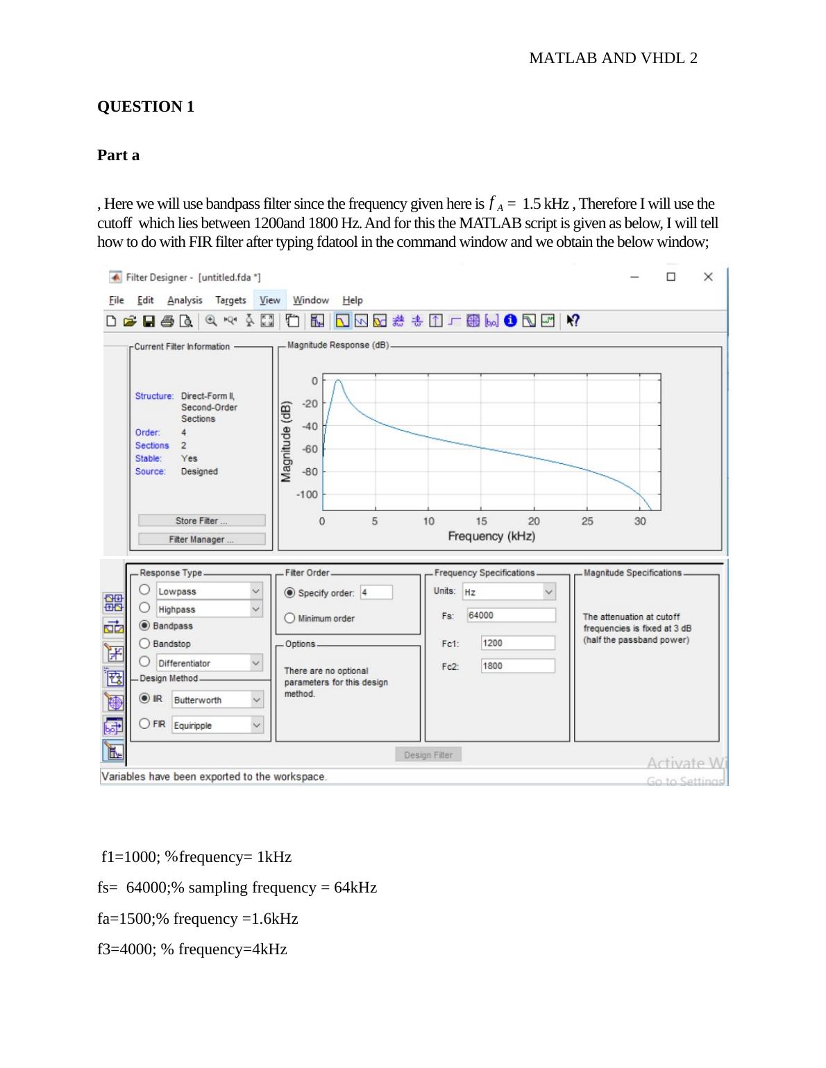
, Here we will use bandpass filter since the frequency given here is f A = 1.5 kHz , Therefore I will use the
cutoff which lies between 1200and 1800 Hz. And for this the MATLAB script is given as below, I will tell
how to do with FIR filter after typing fdatool in the command window and we obtain the below window;
f1=1000; %frequency= 1kHz
fs= 64000;% sampling frequency = 64kHz
fa=1500;% frequency =1.6kHz
f3=4000; % frequency=4kHz
QUESTION 1
Part a
, Here we will use bandpass filter since the frequency given here is f A = 1.5 kHz , Therefore I will use the
cutoff which lies between 1200and 1800 Hz. And for this the MATLAB script is given as below, I will tell
how to do with FIR filter after typing fdatool in the command window and we obtain the below window;
f1=1000; %frequency= 1kHz
fs= 64000;% sampling frequency = 64kHz
fa=1500;% frequency =1.6kHz
f3=4000; % frequency=4kHz
MATLAB AND VHDL 3
t=0:1/fs:5/f1;
x=0.1.*sin(2*pi*f1*t)+1*sin(2*pi*fa.*t)+0.1*sin(2*f3.*t)+0.05.*randn(1, length(t));% adding
three signal with noise %% filter design from FDATOOL ( command:fdatool)
% Design a suitable bandpass filter having cutoff frequency 1200Hz and 1800Hz
% Hz sample frequency of 64000Hz with an order of 10 (Butterworth Model)
% type fdatool in command window,
Part b
[b a ] =sos2tf(SOS,G);
y= filter (b,a,x);
Plot(y)
%%%%%%%%%%%%%%%%%%%%%%%%%%%%%%%%%%%%%%%%%%%%%
I will attach the figures from the MATLAB
Fist figure: FIR, Butterworth – order 4
Second figure: FIR, Butterworth – order 10
Third figure: FIR, Butterworth – order 14
First figure: input
Critical Point: 1 FIR filter required less order than the IIR filter for getting faithful output.
Second figure: If the order increase computation will increase
Third figure : If you increase the order, FIR filter will go to unstable system (order 4 )
End of preview
Want to access all the pages? Upload your documents or become a member.