MATLAB MEM 355 Control System Design for Lateral Dynamics of Boeing 747
VerifiedAdded on 2023/05/28
|10
|867
|82
AI Summary
This article discusses the MATLAB MEM 355 Control System Design for Lateral Dynamics of Boeing 747. It covers constructing a state equation set with the rudder actuator and washout filter, stability determination, rudder actuator, washout filter, compensator transfer function and more. The article includes code snippets and figures to help understand the concepts better.
Contribute Materials
Your contribution can guide someone’s learning journey. Share your
documents today.

Table of Contents
Project MATLAB MEM 355 Control System Design ................................................................ 1
PART 1 ............................................................................................................................. 2
PART II ............................................................................................................................ 2
PART III ........................................................................................................................... 6
PART IV ........................................................................................................................... 8
Project MATLAB MEM 355 Control System De-
sign
%Lateral Dynamics of Boeing 747 (at mach 0.8 and 40,000ft)
%Beta-sideslip angle, r-yaw rate, p-roll rate, theta-roll angle
clear
close all
clc
%Creating the matrix for the aircraft
A=[-0.0558 -0.9968 0.0802 0.0415;0.598 -0.115 -0.0318 0;
-3.05 0.388 -0.465 0;0 0.0805 1 0];
B=[0.00729;-0.475;0.153;0];
[V,D]=eig(A);
disp('The eigenvalues are:')
disp(V);
disp('The eigenfunctions are:')
disp(D);
The eigenvalues are:
0.1994 - 0.1063i 0.1994 + 0.1063i -0.0172 + 0.0000i 0.0067 +
0.0000i
-0.0780 - 0.1333i -0.0780 + 0.1333i -0.0118 + 0.0000i 0.0404 +
0.0000i
-0.0165 + 0.6668i -0.0165 - 0.6668i -0.4895 + 0.0000i -0.0105 +
0.0000i
0.6930 + 0.0000i 0.6930 + 0.0000i 0.8717 + 0.0000i 0.9991 +
0.0000i
The eigenfunctions are:
-0.0329 + 0.9467i 0.0000 + 0.0000i 0.0000 + 0.0000i 0.0000 +
0.0000i
0.0000 + 0.0000i -0.0329 - 0.9467i 0.0000 + 0.0000i 0.0000 +
0.0000i
0.0000 + 0.0000i 0.0000 + 0.0000i -0.5627 + 0.0000i 0.0000 +
0.0000i
0.0000 + 0.0000i 0.0000 + 0.0000i 0.0000 + 0.0000i -0.0073 +
0.0000i
1
Secure Best Marks with AI Grader
Need help grading? Try our AI Grader for instant feedback on your assignments.

PART 1
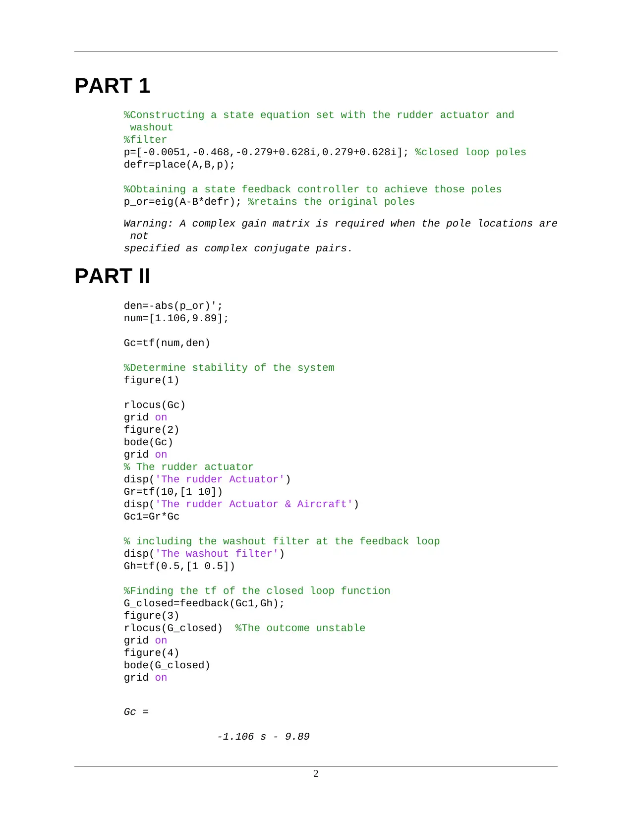
%Constructing a state equation set with the rudder actuator and
washout
%filter
p=[-0.0051,-0.468,-0.279+0.628i,0.279+0.628i]; %closed loop poles
defr=place(A,B,p);
%Obtaining a state feedback controller to achieve those poles
p_or=eig(A-B*defr); %retains the original poles
Warning: A complex gain matrix is required when the pole locations are
not
specified as complex conjugate pairs.
PART II
den=-abs(p_or)';
num=[1.106,9.89];
Gc=tf(num,den)
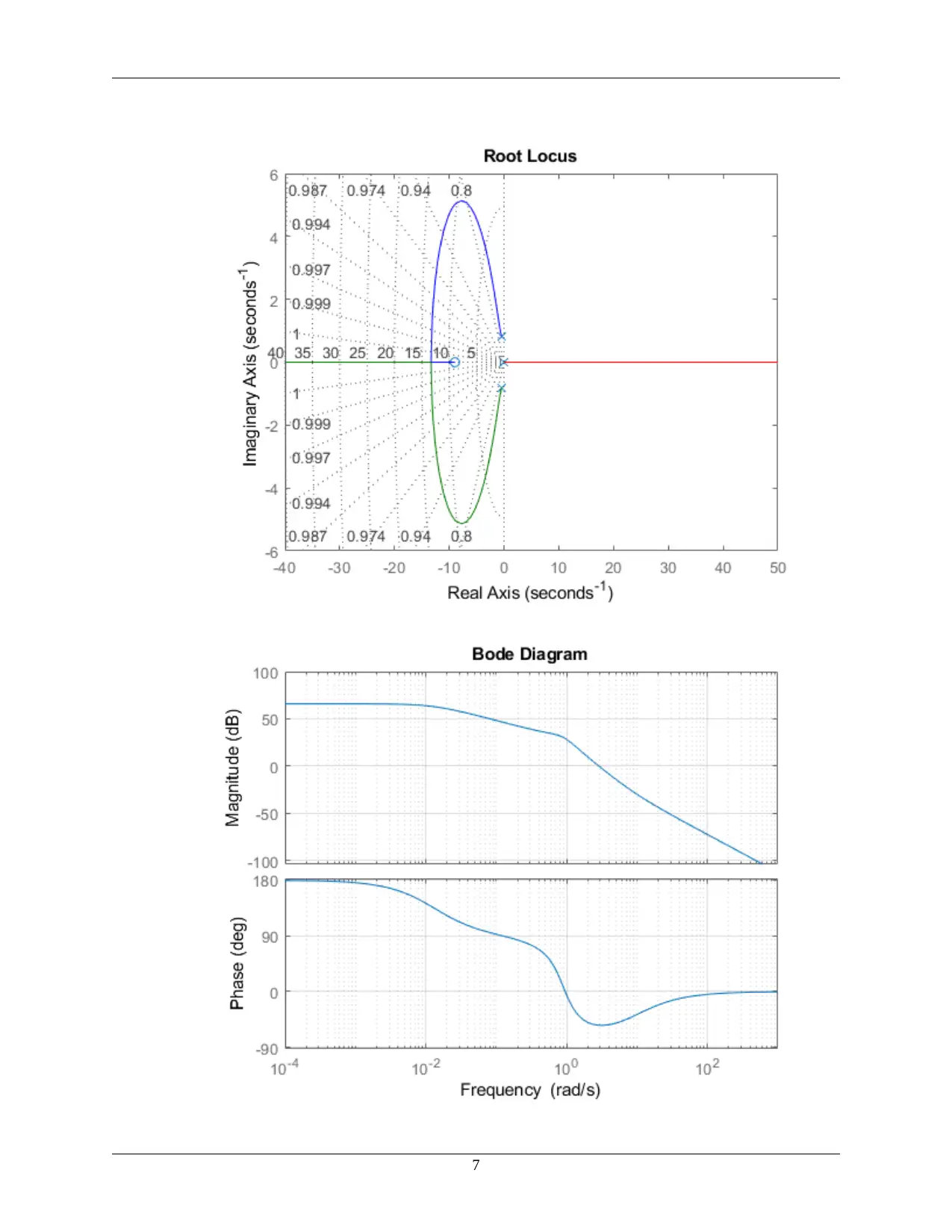
%Determine stability of the system
figure(1)
rlocus(Gc)
grid on
figure(2)
bode(Gc)
grid on
% The rudder actuator
disp('The rudder Actuator')
Gr=tf(10,[1 10])
disp('The rudder Actuator & Aircraft')
Gc1=Gr*Gc
% including the washout filter at the feedback loop
disp('The washout filter')
Gh=tf(0.5,[1 0.5])
%Finding the tf of the closed loop function
G_closed=feedback(Gc1,Gh);
figure(3)
rlocus(G_closed) %The outcome unstable
grid on
figure(4)
bode(G_closed)
grid on
Gc =
-1.106 s - 9.89
2

------------------------------------------
0.468 s^3 + 0.0051 s^2 + 0.6872 s + 0.6872
Continuous-time transfer function.
The rudder Actuator
Gr =
10
------
s + 10
Continuous-time transfer function.
The rudder Actuator & Aircraft
Gc1 =
-11.06 s - 98.9
----------------------------------------------------
0.468 s^4 + 4.685 s^3 + 0.7382 s^2 + 7.559 s + 6.872
Continuous-time transfer function.
The washout filter
Gh =
0.5
-------
s + 0.5
Continuous-time transfer function.
3

4
Secure Best Marks with AI Grader
Need help grading? Try our AI Grader for instant feedback on your assignments.

5

PART III
p2=[-0.0253, -2.34, -1.39+1.34i,-1.39-1.34i];
c=[0,0,0,1];
defr2=place(A,B,p2)
%Obtaining a state feedback controller to achieve those poles
p_orB=eig(A-B*defr2) %retains the original poles
den=-abs(p_orB)';
num=[5.53 49.5];
GcB=tf(num,den);
figure(5)
rlocus(GcB) %observer for the system
grid on
figure(6)
bode(GcB)
grid on
defr2 =
12.7251 -10.3657 -3.3136 0.1852
p_orB =
-2.3400 + 0.0000i
-1.3900 + 1.3400i
-1.3900 - 1.3400i
-0.0253 + 0.0000i
6

7
Paraphrase This Document
Need a fresh take? Get an instant paraphrase of this document with our AI Paraphraser

PART IV
... Compensator transfer function
L=place(A',c',p2)'
eig(A-L*c)
Ac=A-B*defr2-L*c;
Bc=L;
Cc=defr2;
Gcss=ss(Ac,Bc,Cc,0);
Gcw=tf(Gcss);
rt=zpk(Gcw)
% Defining the root locus of the compensator
figure(7)
rlocus(rt)
grid on
figure(8)
L =
-1.3005
-1.8512
6.7054
4.5095
ans =
-2.3400 + 0.0000i
-1.3900 + 1.3400i
-1.3900 - 1.3400i
-0.0253 + 0.0000i
rt =
-18.744 (s-2.351) (s+0.7137) (s+0.006711)
------------------------------------------
(s+2.727) (s+3.646) (s^2 + 3.282s + 9.264)
Continuous-time zero/pole/gain model.
8

9

PREFORMATTED
TEXT
bode(rt)
grid on
Published with MATLAB® R2018b
10
TEXT
bode(rt)
grid on
Published with MATLAB® R2018b
10
1 out of 10
Your All-in-One AI-Powered Toolkit for Academic Success.
+13062052269
info@desklib.com
Available 24*7 on WhatsApp / Email
![[object Object]](/_next/static/media/star-bottom.7253800d.svg)
Unlock your academic potential
© 2024 | Zucol Services PVT LTD | All rights reserved.