Design and Development of Quadcopter for Advanced Manufacturing-II
Added on 2020-10-03
42 Pages11891 Words479 Views
ME5600B PROJECT IN ADVANCED MANUFACTURING-II DESIGN AND DEVELOPMENT OF QUADCOPTER Rajagopalan Eswaran A0165156A Department of Mechanical Engineering Year: 2018
1 TABLE OF CONTENTS LIST OF FIGURES................................................................................................................................ 3 Abstract................................................................................................................................................... 5 1. INTRODUCTION.............................................................................................................................. 6 1.1 COMPONENTS AND WORKING.............................................................................................. 6 1.2 3D PRINTING IN DRONE DESIGN.......................................................................................... 7 1.3 MOTIONS IN QUADCOPTER................................................................................................... 7 2. ELECTRONIC COMPONENTS SELECTION................................................................................. 8 2.1 MOTOR........................................................................................................................................ 8 2.2 PROPELLERS............................................................................................................................ 10 2.3 ELECTRONIC SPEED CONTROLLER................................................................................... 11 2.4 FLIGHT CONTROLLER........................................................................................................... 13 2.5 BATTERY.................................................................................................................................. 16 2.6 RADIO SYSTEM....................................................................................................................... 17 3. FRAME DESIGN............................................................................................................................. 19 3.1 FRAME DESIGN-INITIAL:...................................................................................................... 20 3.2 FINITE ELEMENT ANALYSIS OF FLIGHT ARM................................................................ 22 3.2.1 CALCULATION OF THRUST FORCE............................................................................. 22 3.2.2 FEA FOR PLA MATERIAL............................................................................................... 22 3.2.3 FEA FOR ABS MATERIAL............................................................................................... 24 3.3 INFERENCES............................................................................................................................ 25 3.4 DESIGN UPDATE TRAIL-1:.................................................................................................... 25 4. 3D PRINTING.................................................................................................................................. 26 5. WIRING THE ELECTRONICS....................................................................................................... 26 6. ASSEMBLING THE MODEL......................................................................................................... 27 7. FC CONFIGURATION.................................................................................................................... 28 8. DESIGN UPDATE-TRIAL 2........................................................................................................... 31 8.1 FEA FOR UPDATED DESIGN................................................................................................. 32 8.2 3D PRINTING CARBON FIBER.............................................................................................. 33 8.3 ASSEMBLED MODEL.............................................................................................................. 34 9. NEED FOR DESIGN UPDATE....................................................................................................... 34 10. FINAL DESIGN DEVELOPED..................................................................................................... 35 11. WEIGHT REDUCTION USING 3 MATICS LIGHTWEIGHTS.................................................. 37 11.1 WEIGHT REDUCTION USING 3MATICS........................................................................... 37
2 11.2 FEA FOR LATTICE DEVELOPED MODEL......................................................................... 38 11.3 WEIGHT REDUCTION ACHIEVED..................................................................................... 39 FUTURE FORESIGHT........................................................................................................................ 40 CONCLUSION..................................................................................................................................... 40 REFERENCES..................................................................................................................................... 41
3 LIST OF FIGURES Figure 1 Drone Motion........................................................................................................................... 7 Figure 2 Motor specifications (a).......................................................................................................... 10 Figure 3 Motor Specifications (b)......................................................................................................... 10 Figure 4 Motor...................................................................................................................................... 10 Figure 5 Propellers................................................................................................................................ 11 Figure 6 ESC Protocol Comparison...................................................................................................... 13 Figure 7 ESC Specifications................................................................................................................. 13 Figure 8 Selected ESC.......................................................................................................................... 13 Figure 9 Betaflight F4........................................................................................................................... 15 Figure 10 FC Specifications.................................................................................................................. 16 Figure 11 Battery Specifications........................................................................................................... 17 Figure 12 Battery Selected.................................................................................................................... 17 Figure 13 Receiver Specifications........................................................................................................ 18 Figure 14 Transmitter Specifications.................................................................................................... 18 Figure 15 X-frame................................................................................................................................. 19 Figure 16 H-frame................................................................................................................................. 19 Figure 17 Hybrid X-frame.................................................................................................................... 20 Figure 18 Top plate............................................................................................................................... 20 Figure 19 Bottom plate......................................................................................................................... 21 Figure 20 Arm with standoff................................................................................................................. 21 Figure 21 Assembled view.................................................................................................................... 21 Figure 22 Total Displacement PLA-Initial Design............................................................................... 23 Figure 23 Von-Mises Stress PLA-Initial Design.................................................................................. 23 Figure 24 Total Displacement ABS-Initial Design............................................................................... 24 Figure 25 Von-Mises Stress ABS-Initial Design.................................................................................. 25 Figure 26 Trial-1 Top plate................................................................................................................... 25 Figure 27 Trial-1 Bottom plate............................................................................................................. 26 Figure 28 3D Printed Arm.................................................................................................................... 26 Figure 29 Wiring Diagram of Betaflight F4......................................................................................... 26 Figure 30 Wiring Check........................................................................................................................ 27 Figure 31 Assembled Model-Trial 1..................................................................................................... 27 Figure 32 Port Configuration................................................................................................................ 28 Figure 33 Protocol Configuration......................................................................................................... 28 Figure 34 System Configuration........................................................................................................... 29 Figure 35 Receiver Configuration......................................................................................................... 29 Figure 36 Transmitter Binding and Configuration............................................................................... 30 Figure 37 Accelerometer Configuration............................................................................................... 30 Figure 38 Mode Configuration............................................................................................................. 31 Figure 39 Bottom plate- Trial 2........................................................................................................... 31 Figure 40 Landing leg-Trial 2............................................................................................................... 32 Figure 41 Arm-Trial 2.......................................................................................................................... 32 Figure 42 Standoff-Trial 2................................................................................................................... 32 Figure 43 Total displacement Design trial 2......................................................................................... 33 Figure 44 Von-Mises Stress Design Trial 2......................................................................................... 33
4 Figure 45 Concentric Carbon Fibre Fill................................................................................................ 34 Figure 46 3D Printed Carbon Fibre Arm Full Drone Assembly........................................................... 34 Figure 47 Damaged parts...................................................................................................................... 35 Figure 48 Final leg and Bottom plate design........................................................................................ 35 Figure 49 Final Arm Design................................................................................................................. 36 Figure 50 Final Top plate Design......................................................................................................... 36 Figure 51 Final Model.......................................................................................................................... 36 Figure 52 3D printed Final Model........................................................................................................ 37 Figure 53 Simple cube unit cell............................................................................................................ 37 Figure 54 Total Displacement Simple cube lattice............................................................................... 38 Figure 55 Von-Mises Stress simple cube lattice................................................................................... 39 Figure 56 3D print of Simple cube lattice arm...................................................................................... 40
5 Abstract 3D Printing is an advanced manufacturing methodology which involves adding up of layers of materials to build the object of desired shape. The advantage of 3D printing is that shapes that are very difficult to be built by conventional machining can be made easily by using the additive manufacturing technology. In recent times 3D printing technology is being extensively used to build un-manned remote controlled vehicles known as the drones. This project involves building a quadcopter (drone) from scratch by making the basic design of the frame on our own. Then this design is 3D printed, assembled with the electronic components, made to fly and tested. Carbon fibre printing technology was explored. The concept of lattice lightweights to reduce the frame weight has also been employed using 3-Matics software.
6 1. INTRODUCTION A quadcopter or quadrotor (drone) is a simple flying mechanical vehicle that has four arms, and in each arm there is a motor attached to a propeller. Multicopters with three, six or eight arms are also possible, but work on the same principal as a quadcopter. Two of the rotors turn clockwise, while the other two turn counter clockwise. Quadcopter is aerodynamically unstable, and require a flight controller to convert the input commands into commands that change the RPMs of the propellers to produce the desired motion [1]. Quadcopters differ from a helicopter or a fixed wing aircraft in the way they generate lift and control forces. A helicopter uses its main rotor to generate lift, but also have the ability to vary the pitch of the rotor blades to generate control forces. For an aircraft the lift is generated by the wings, but in a quadcopter the lift is generated by the propellers which generate the thrust force. With the development of electronics in the recent years, the quadcopter has become one of the major hobbies of many people. Many are interested in building their own quadcopter using the electronics that are available in the market for drone building. Advancement in technology has made the electronics quite cheap, thus making this concept readily available for everyone single person’s reach. People either buy the frame or design one on their own for their quadcopter. The application of quadcopter has been continuously explored in various fields. Drones with FPV cameras and surveillance camera are being extensively used in the field of defence technology. Also drones fitted with fighting equipment are currently employed in modern warfare. Drones are used to clean window panes and other places which are at an elevated distance. Recently drones are used for package delivery system to deliver the parcels. Majorly it is being employed as a recreational sport and hobby for many tech loving enthusiasts. 1.1 COMPONENTS AND WORKING The quadcopter consists of the following major components. They are: 1.Frame 2.Motor 3.ESC 4.Flight Controller 5.PDB (If required) 6.Battery 7.Propellers 8.Radio systems The electronic parts are mounted on the frame after they are soldered. The fight controller is configured and the accelerometer and the gyro are preset. Once the power source is connected a 5V supply is provided to the flight controller. The flight controller is activated and the signals are sent to the ESCs and the receiver respectively. The transmitter or the remote control is then bound to the receiver by turning it on. The ESC which is now active supplies the power to the motor. Once the drone is armed the propellers begin to rotate at a fixed rpm preset. The trimming and other perquisites are done in the transmitter and the throttle is increased to 50%. The propellers now develop sufficient thrust for the lift and the
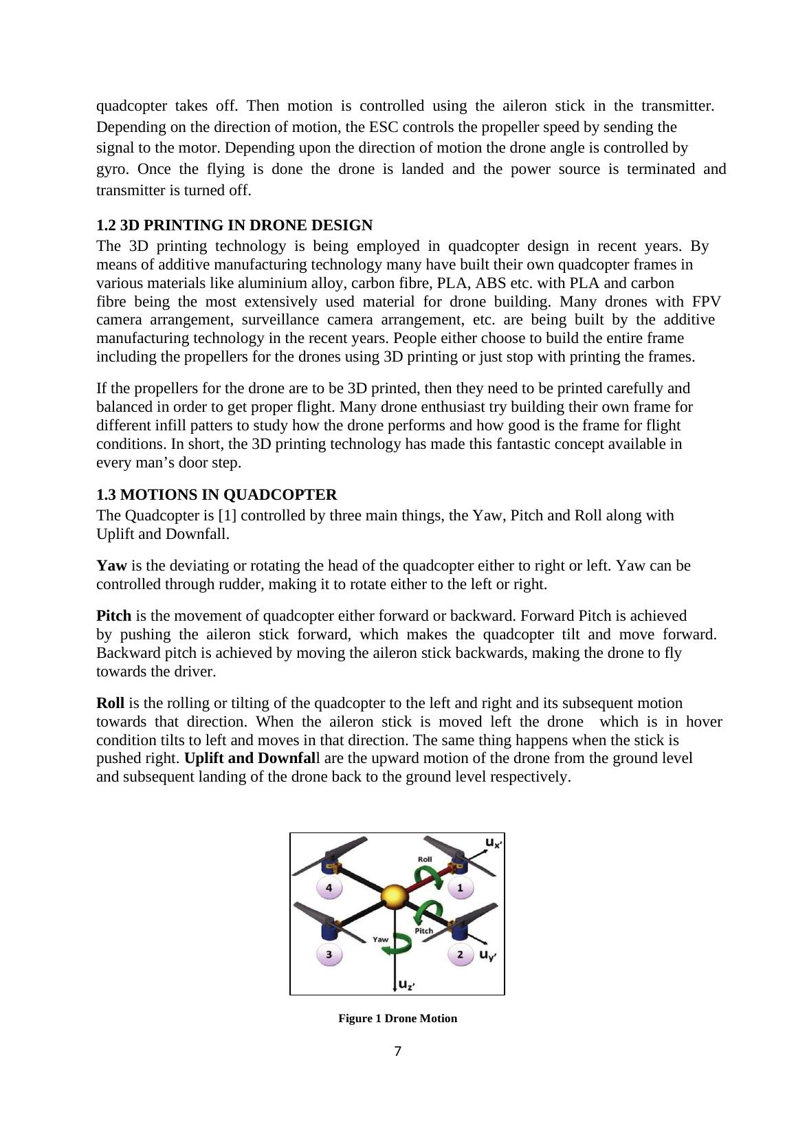
7 quadcopter takes off. Then motion is controlled using the aileron stick in the transmitter. Depending on the direction of motion, the ESC controls the propeller speed by sending the signal to the motor. Depending upon the direction of motion the drone angle is controlled by gyro. Once the flying is done the drone is landed and the power source is terminated and transmitter is turned off. 1.2 3D PRINTING IN DRONE DESIGN The 3D printing technology is being employed in quadcopter design in recent years. By means of additive manufacturing technology many have built their own quadcopter frames in various materials like aluminium alloy, carbon fibre, PLA, ABS etc. with PLA and carbon fibre being the most extensively used material for drone building. Many drones with FPV camera arrangement, surveillance camera arrangement, etc. are being built by the additive manufacturing technology in the recent years. People either choose to build the entire frame including the propellers for the drones using 3D printing or just stop with printing the frames. If the propellers for the drone are to be 3D printed, then they need to be printed carefully and balanced in order to get proper flight. Many drone enthusiast try building their own frame for different infill patters to study how the drone performs and how good is the frame for flight conditions. In short, the 3D printing technology has made this fantastic concept available in every man’s door step. 1.3 MOTIONS IN QUADCOPTER The Quadcopter is [1] controlled by three main things, the Yaw, Pitch and Roll along with Uplift and Downfall. Yaw is the deviating or rotating the head of the quadcopter either to right or left. Yaw can be controlled through rudder, making it to rotate either to the left or right. Pitch is the movement of quadcopter either forward or backward. Forward Pitch is achieved by pushing the aileron stick forward, which makes the quadcopter tilt and move forward. Backward pitch is achieved by moving the aileron stick backwards, making the drone to fly towards the driver. Roll is the rolling or tilting of the quadcopter to the left and right and its subsequent motion towards that direction. When the aileron stick is moved left the drone which is in hover condition tilts to left and moves in that direction. The same thing happens when the stick is pushed right. Uplift and Downfall are the upward motion of the drone from the ground level and subsequent landing of the drone back to the ground level respectively. Figure 1 Drone Motion
End of preview
Want to access all the pages? Upload your documents or become a member.