UEE22011 Module 5: Solve DC Circuit Problems and Measurements

Verified

Added on  2023/06/03

|5
|839
|221
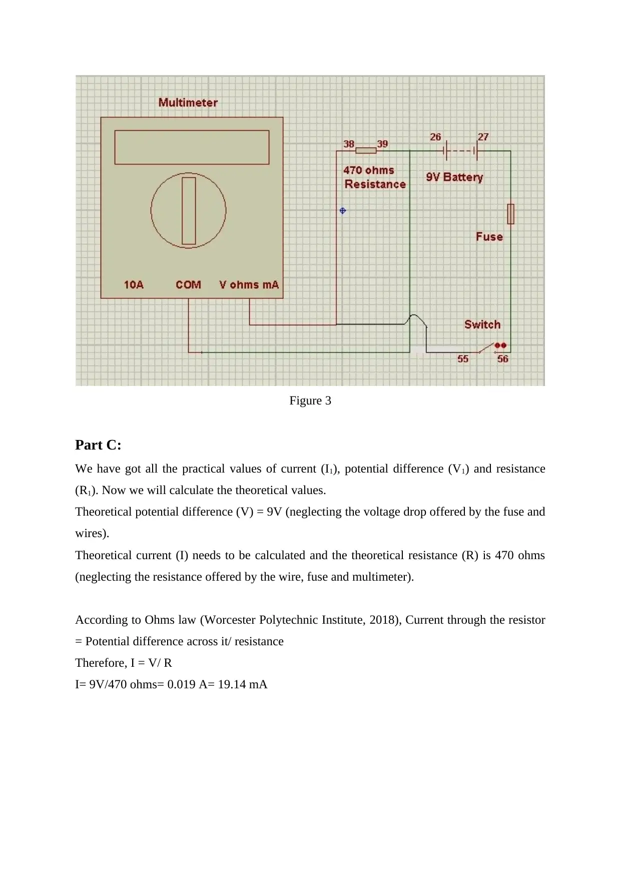
Practical Assignment
AI Summary
This assignment solution details the practical measurement of resistance, current, and voltage in a DC circuit, following the guidelines of the UEE22011 Certificate II in Electrotechnology (Career Start) Module 5. The solution outlines the steps taken to measure resistance (R1), current (I1), and potential difference (V1) using a multimeter within a given circuit configuration. It also includes the calculation of theoretical values for current and potential difference based on Ohm's Law, allowing for a comparison between measured and theoretical results. The assignment emphasizes the practical application of electrical principles and the use of measurement tools, providing a comprehensive understanding of DC circuit analysis. References to relevant sources such as Electrical4u, Encyclopaedia Britannica, and Worcester Polytechnic Institute are included to support the analysis. The solution is designed to assist students in understanding the practical aspects of electrical circuits and applying theoretical knowledge to real-world scenarios.
Document Page
Part B:
Measurement of Resistance (R1):
Set the multimeter to ohms range in which 470 ohms lies and rotate the knob. It is possible
that it has some error. It can be checked connecting the two leads together. If any resistance
(Rouse, 2015) is found then it has to be deducted from the final reading. Now, connect the
lead marked ‘V ohms mA’ of the multimeter to ‘38’ of the electronic playground (one end of
470 ohms resistor) and the lead marked ‘COM’ to ‘39’ of the electronic playground (other
end of 470 ohms resistor) without touching the fingers as shown in figure 1. Note the reading
as R1. Note that if the error reading was found earlier it has to be deducted from R1 to get
resultant R1.
Figure 1
Measurement of Current (I1):
Disconnect all the connections. In order to measure the current (Encyclopaedia Britannica,
2018) through the 470 ohms resistor we need to first set the multimeter to the minimum DC
mA range. Connect the lead marked ‘V ohms mA’ of the multimeter to ‘38’ (one end of 470
ohms resistor) as marked on the electronic playground. ‘39’ point to ‘26’ point which is the
negative end of the 9V battery. ‘27’ point, which is the positive end of the same battery to
one end of the fuse. The other end of the fuse has to be connected to the ‘56’ point which is
tabler-icon-diamond-filled.svg

Paraphrase This Document

Need a fresh take? Get an instant paraphrase of this document with our AI Paraphraser
Document Page
one end of the switch. The other end ‘55’ finally goes back to the ‘COM’ of the multimeter as
shown in figure 2. Rotate the knob in the ampere range till any value is shown on the Liquid
Crystal Display (LCD) of the multimeter. Note the value as I1 when displayed.
Figure 2
Measurement of Potential difference (V1):
Disconnect all the connections. In order to measure the potential difference (Electrical4u,
2018) across the 470 ohms resistor we need to first set the multimeter to the minimum DC
volts range. Connect the lead marked ‘V ohms mA’ of the multimeter to ‘38’ (one end of 470
ohms resistor) as marked on the electronic playground. ‘39’ point to ‘26’ point which is the
negative end of the 9V battery as well as to the ‘COM’ of the multimeter. ‘27’ point, which is
the positive end of the same battery to one end of the fuse. The other end of the fuse has to be
connected to the ‘56’ point which is one end of the switch. The other end ‘55’ finally goes
back to ‘38’ (one end of 470 ohms resistor) as shown in figure 3. Rotate the knob in the
potential difference range till any value is shown on the Liquid Crystal Display (LCD) of the
multimeter. Note the value as V1 when displayed.
Document Page
Figure 3
Part C:
We have got all the practical values of current (I1), potential difference (V1) and resistance
(R1). Now we will calculate the theoretical values.
Theoretical potential difference (V) = 9V (neglecting the voltage drop offered by the fuse and
wires).
Theoretical current (I) needs to be calculated and the theoretical resistance (R) is 470 ohms
(neglecting the resistance offered by the wire, fuse and multimeter).
According to Ohms law (Worcester Polytechnic Institute, 2018), Current through the resistor
= Potential difference across it/ resistance
Therefore, I = V/ R
I= 9V/470 ohms= 0.019 A= 19.14 mA
Document Page
In tabular form,
Resistance ohms
Measured (R1) -
Theoretical (R) 470
Current mA
Measured (I1) -
Theoretical (I) 19.14
Potential difference volts
Measured (V1) -
Theoretical (V) 9
tabler-icon-diamond-filled.svg

Paraphrase This Document

Need a fresh take? Get an instant paraphrase of this document with our AI Paraphraser
Document Page
References
Electrical4u (2018) Voltage or Electric Potential Difference [Online]. Available from:
https://www.electrical4u.com/voltage-or-electric-potential-difference/ [Accessed 16 October
2018].
Encyclopaedia Britannica (2018) Electric current [Online]. Available from:
https://www.britannica.com/science/electric-current [Accessed 16 October 2018].
Rouse, M. (2015). Resistance. [Online]. Available from:
https://whatis.techtarget.com/definition/resistance [Accessed 16 October 2018].
Worcester Polytechnic Institute (2018) Hands-on Activity: Ohm's Law I [Online]. Available
from: https://www.teachengineering.org/activities/view/ohm1_act_joy [Accessed 16 October
2018].
chevron_up_icon
1 out of 5
circle_padding
hide_on_mobile
zoom_out_icon
[object Object]