Analysis of Audio Amplifier Circuit using LM386 IC and Orcad
VerifiedAdded on 2021/08/03
|9
|1695
|501
Practical Assignment
AI Summary
This assignment focuses on the construction, measurement, and evaluation of an audio amplifier circuit using the LM386 integrated circuit. The study utilizes Orcad Capture software for schematic design and PSpice for simulation and analysis. The circuit's frequency response and waveforms are assessed across AC sweep and transient domains. The report details the types of audio amplifiers, the working principle of the LM386, and the simulation settings used. The results include AC sweep analysis showing frequency response, transient analysis demonstrating the impact of resistance and frequency on gain, and gain calculations. The findings highlight the relationship between resistance and gain, concluding that the LM386 is suitable for low-voltage consumer devices and providing insights into circuit behavior and performance.
Measurement & Evaluation of Audio Amplifier
Circuit using LM386
1. Introduction
1.1 Aim:
The aim of the study is to construct an audio amplifier circuit using IC, LM 386.The built
circuit can be used in low voltage consumer devices. Orcad Capture software is used to
build the schematic of the amplifier. PSpice is used to measure and evaluate the
frequency response and waveforms of the circuit in three different domains which are:
a) AC Sweep
b) Transient ( Time Domain)
c) Time Domain ( Transient)
1.2 Applications
An audio amplifier is used to produce the sound output out of all devices. The
audio amplifier are used in various devices which includes (Anon., n.d.):
a) Home audio systems
b) TV sound systems
c) Intercom
d) Portable MP3 players
e) Radio
f) Robots
g) Acoustic Weapons
h) Ultrasonic/Small servo/Line Drivers
i) Power Converters
1.3 Background
1.3.1 LM386 Audio Amplifier:
A device used to amplify (increase) the amplitude of a low power audio signal
is known as amplifier. The output of signal is measured in volts or amperes.
Signals are merely composed of frequencies with in the human hearing range
i.e. 20Hz to 20,000 Hz. The low voltage audio amplifier, LM386 IC gain is 20
dB, that can be increased to any value within the range of 20 and 200 dB by
Paraphrase This Document
Need a fresh take? Get an instant paraphrase of this document with our AI Paraphraser
basically inserting an external series Resistance/capacitance circuit between
gain controlling pin i.e. pin 1 and pin 8 of the IC. The increase in AC power is
from the i/p terminals to the o/p terminals is due to the biasing of the circuit
provided by the DC voltage source. LM386 pin 2 & pin 3 are the inverting and
non-inverting inputs of the amplifier. Pin 2 is always connected to the ground.
The output pin is pin 5. Pin 7 sets the path of decoupling whereas pin 6 and
pin 4 are the used to supply the power to IC LM386. A 9v power supply is
used in construction the audio amplifier circuit (Self, n.d.).
Figure 1 Pin Diagram of LM386
1.3.2 Types of Audio Amplifier Circuits:
Amplifiers are categorized according to their input & output parameters.
Various types of amplifier circuits are described as follows (Vimal Raj V & S,
2017) (Anon., n.d.):
a) Audio frequency amplifier: A type of amplifier used to amplify audio
frequencies up to 100 kHz. Loudspeakers are driven by the power
provided by audio frequency amplifier.
b) Midway frequency amplifier: A tuned amp whose aim is to amplify
the voltage of the signals of TV/Radar, before the audio or video
information carried by the signal is separated or demodulated from the
radio signal. The frequency at which the amplifier operates is intermediate
frequency.
c) Radio frequency amplifiers: A tuned amplifier used to increase the
power of low-frequency radio signal. The tuning of the circuit can be
adjusted depending on the amplifier purpose.
d) Ultrasonic Amplifiers: An amplifier which amplify the ultrasonic waves
from 20 kHz up to about 100 kHz. Ultrasonic cleaning & ultrasound
scanning can be performed using ultrasonic amplifier.
e) Wideband Amplifiers: It amplifies a band of frequencies up to several
tens of MHZ. Measurement of signals spreading over a wide range of
frequencies is performed through this amplifier.
f) Direct Coupled Amplifiers: A type of amplifier used to amplify very low
frequency signals. It is used to amplify DC i.e. zero frequency. It is widely
used in measuring instruments & control systems.
g) Video Amplifiers: A wide band amplifier used to improve the signals of
the video and display it with high resolution.
h) Buffer Amplifiers: It is used for the transformation of electrical
impedance from one circuit to another.
i) Operational Amplifiers: A type of voltage amplifier used to perform
mathematical operations on voltages such as addition subtraction etc.
1.4 OrCAD Software Types & Features
OrCAD a widely known software used for designing and simulation of electronic
circuits. The software also has options of PCB designing and analysis of
electronic circuits. The applications of software are as follows (Anon., 2020):
a) OrCAD Capture (CIS): An application used to draw a schematic of the circuit
using a variety of provided circuit symbols. It can also export the schematic
to other circuit board designers.
b) PSpice: A simulation software used to simulate and analyze the captured
circuit. It is also used for the verification of analog and mixed-signal circuits
and supports the following categories of analyses:
i. Transient Analyses
ii. AC Analyses
iii. DC Analyses
⊘ This is a preview!⊘
Do you want full access?
Subscribe today to unlock all pages.

Trusted by 1+ million students worldwide
c) PCB Designer: An application used to design printed circuit boards (PCB).
The output of these files are sent to the workshop for the manufacturing of
PCB. The application uses the schematic built on OrCAD capture to capture
data about a specific circuit symbol and its similar PCB footprint.
The OrCAD suite has following features (Anon., n.d.):
1. User interface customization
2. Modification of 3D primitives
3. User friendly component replacements & extensive component libraries
4. Command Customization
5. Editable layers of PCB design
6. Interactive/group/scribble/shape routing
7. Integration with other software such as SOLID WORKS etc.
2. LM386 Audio Power Amplifier Circuit
2.1 Working Principle
After the system is powered on, an audio signal is fed into the input pin of LM386
which increases the amplitude of the given signal and gives the output at pin 5 of
the IC. The o/p signal is passed through the capacitor and is fed in to the speaker
(output device) (Saha, et al., 2018).
2.2 Schematic
Paraphrase This Document
Need a fresh take? Get an instant paraphrase of this document with our AI Paraphraser
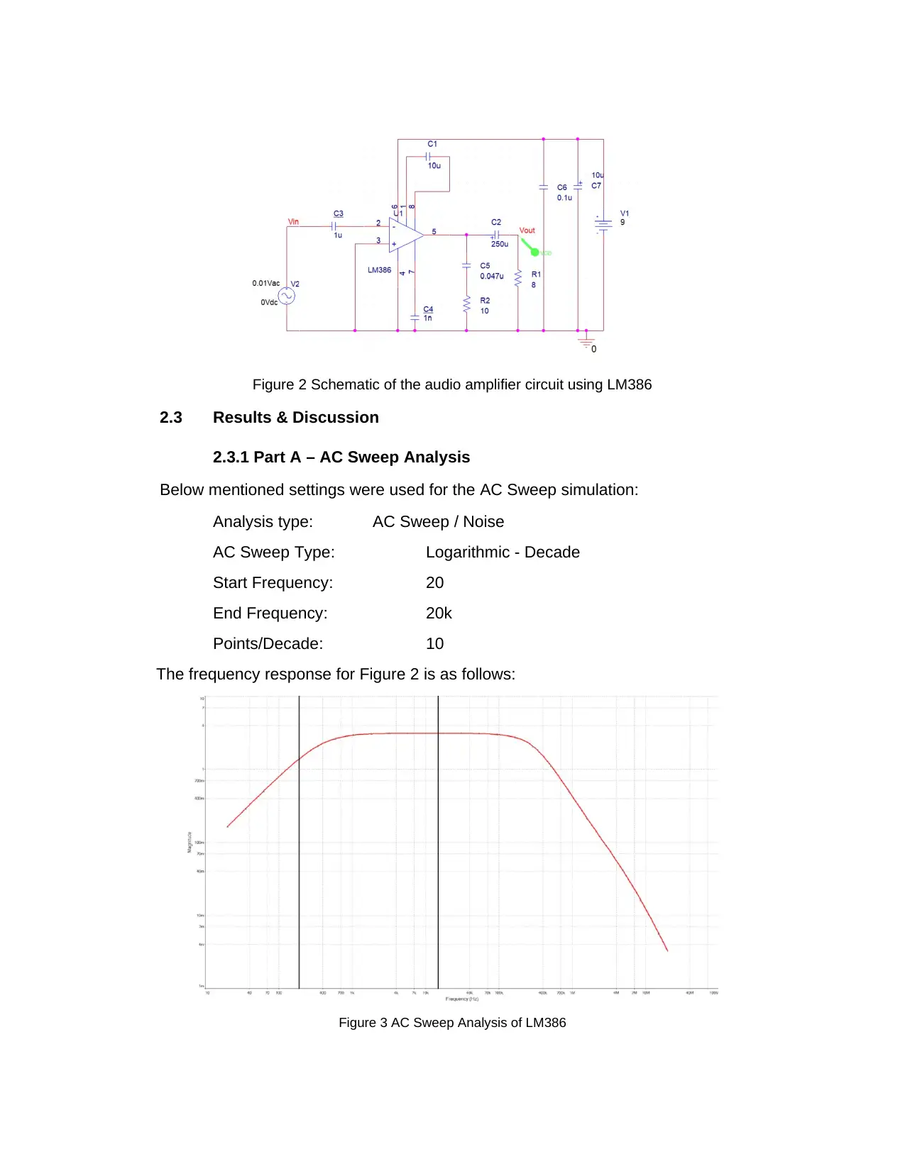
Figure 2 Schematic of the audio amplifier circuit using LM386
2.3 Results & Discussion
2.3.1 Part A – AC Sweep Analysis
Below mentioned settings were used for the AC Sweep simulation:
Analysis type: AC Sweep / Noise
AC Sweep Type: Logarithmic - Decade
Start Frequency: 20
End Frequency: 20k
Points/Decade: 10
The frequency response for Figure 2 is as follows:
Figure 3 AC Sweep Analysis of LM386
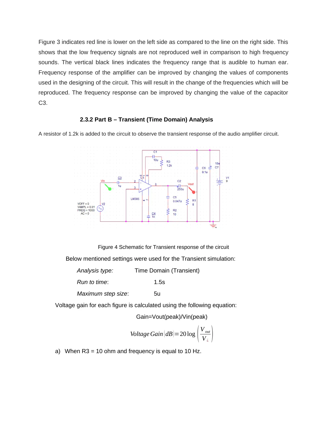
Figure 3 indicates red line is lower on the left side as compared to the line on the right side. This
shows that the low frequency signals are not reproduced well in comparison to high frequency
sounds. The vertical black lines indicates the frequency range that is audible to human ear.
Frequency response of the amplifier can be improved by changing the values of components
used in the designing of the circuit. This will result in the change of the frequencies which will be
reproduced. The frequency response can be improved by changing the value of the capacitor
C3.
2.3.2 Part B – Transient (Time Domain) Analysis
A resistor of 1.2k is added to the circuit to observe the transient response of the audio amplifier circuit.
Figure 4 Schematic for Transient response of the circuit
Below mentioned settings were used for the Transient simulation:
Analysis type: Time Domain (Transient)
Run to time: 1.5s
Maximum step size: 5u
Voltage gain for each figure is calculated using the following equation:
Gain=Vout(peak)/Vin(peak)
Voltage Gain ( dB )=20 log ( V out
V ¿ )
a) When R3 = 10 ohm and frequency is equal to 10 Hz.
⊘ This is a preview!⊘
Do you want full access?
Subscribe today to unlock all pages.

Trusted by 1+ million students worldwide
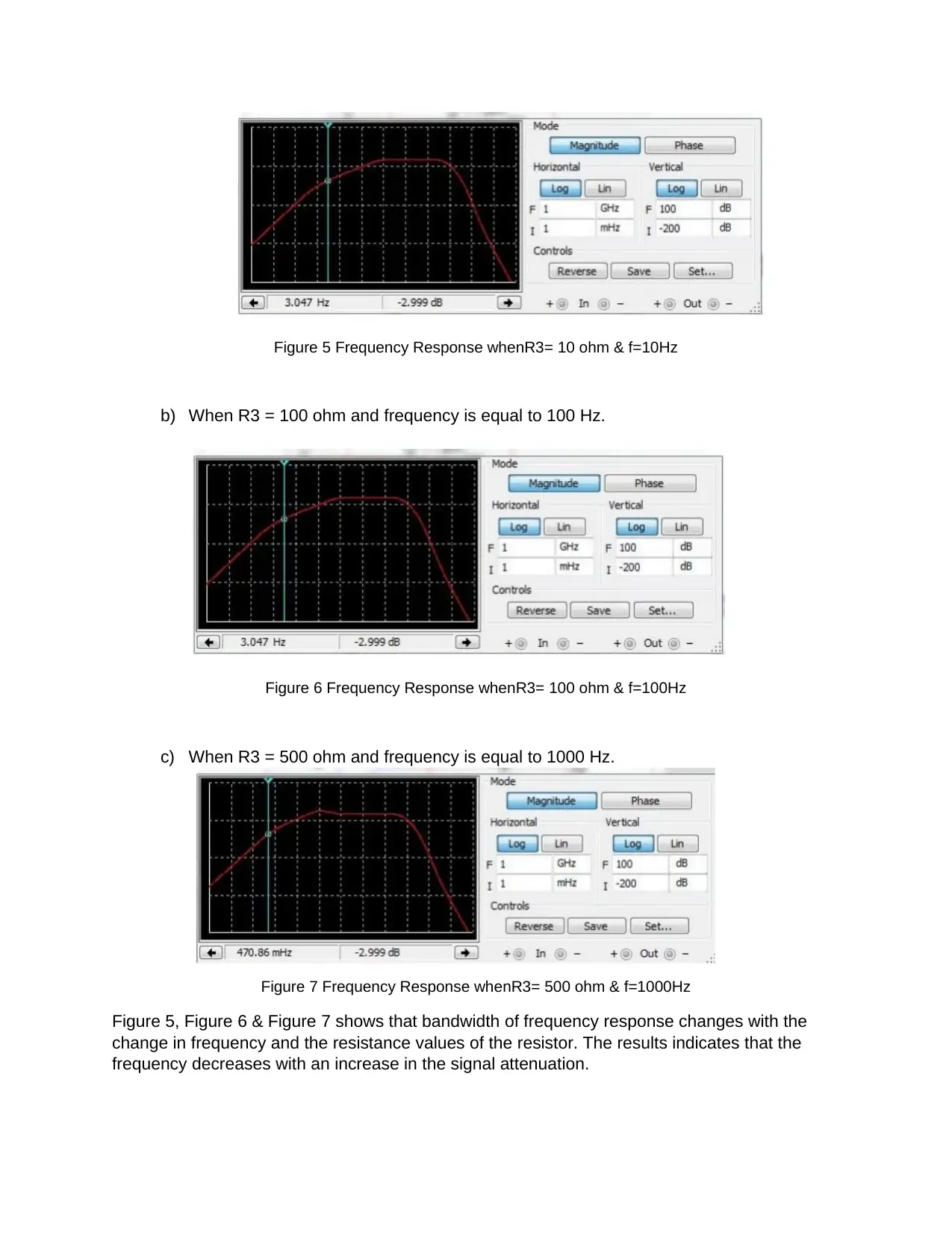
Figure 5 Frequency Response whenR3= 10 ohm & f=10Hz
b) When R3 = 100 ohm and frequency is equal to 100 Hz.
Figure 6 Frequency Response whenR3= 100 ohm & f=100Hz
c) When R3 = 500 ohm and frequency is equal to 1000 Hz.
Figure 7 Frequency Response whenR3= 500 ohm & f=1000Hz
Figure 5, Figure 6 & Figure 7 shows that bandwidth of frequency response changes with the
change in frequency and the resistance values of the resistor. The results indicates that the
frequency decreases with an increase in the signal attenuation.
Paraphrase This Document
Need a fresh take? Get an instant paraphrase of this document with our AI Paraphraser
2.3.3 Part C – Relationship of R3 and Gain
Different values of gain are calculated for different values of input frequencies mentioned
in Table 1. Voltage gain for each figure is calculated using the following equation:
Gain=Vout(peak)/Vin(peak)
Table 1 Gain Calculations
Resistor (R3) Frequency Gain
10 ohm 10 Hz 0.799
100 ohm 100 Hz 0.850
500 ohm 1000 Hz 1.677
Gain and resistance are directly proportional to each other. The values of gain in
Table 1 show that value of gain increases with an increase in the resistance of the
resistors.
Conclusion
An audio power amplifier circuit was built using an integrated circuit LM386. The amplitude and
frequency response of the circuit was observed in different domain like AC sweep analysis,
transient analysis and relationship between the gain and resistance values of resistors was also
observed. IC LM386 are widely in consumer products that works on low voltage. The amplifier
circuit has other advantages as well such as less power consumption, less harmonic distortion,
adjustable gain adjustment and a good range of power supply voltage.
References
Anon., 2020. Orcad. [Online]
Available at: https://www.orcad.com/products/orcad-pcb-designer/features
[Accessed 15 December 2020].
Anon., n.d. Electroschematics. [Online]
Available at: https://www.electroschematics.com/wp-content/uploads/2008/09/lm386.pdf
[Accessed 15 December 2020].
Anon., n.d. Elprocus. [Online]
Available at: https://www.elprocus.com/types-of-amplifiers-with-workings/
[Accessed 15 December 2020].
Anon., n.d. Wikipedia. [Online]
Available at: https://en.wikipedia.org/wiki/OrCAD#References
[Accessed 15 December 2020].
Saha, A., Sarkar, S., Jaseem, M. & Mallik, S., 2018. Audio Power Amplifier, s.l.: s.n.
Self, D., n.d. Audio Power Amplifi er Design. 5th ed. s.l.:s.n.
Vimal Raj V & S, A., 2017. Comparative Study of Audio Amplifiers. IOSR Journal of Electronics
and Communication Engineering, 12(1).
⊘ This is a preview!⊘
Do you want full access?
Subscribe today to unlock all pages.

Trusted by 1+ million students worldwide
1 out of 9
Related Documents
Your All-in-One AI-Powered Toolkit for Academic Success.
+13062052269
info@desklib.com
Available 24*7 on WhatsApp / Email
![[object Object]](/_next/static/media/star-bottom.7253800d.svg)
Unlock your academic potential
Copyright © 2020–2025 A2Z Services. All Rights Reserved. Developed and managed by ZUCOL.


