Electronic Test Equipment
VerifiedAdded on 2020/03/23
|8
|971
|125
AI Summary
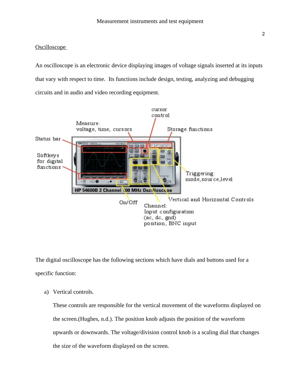
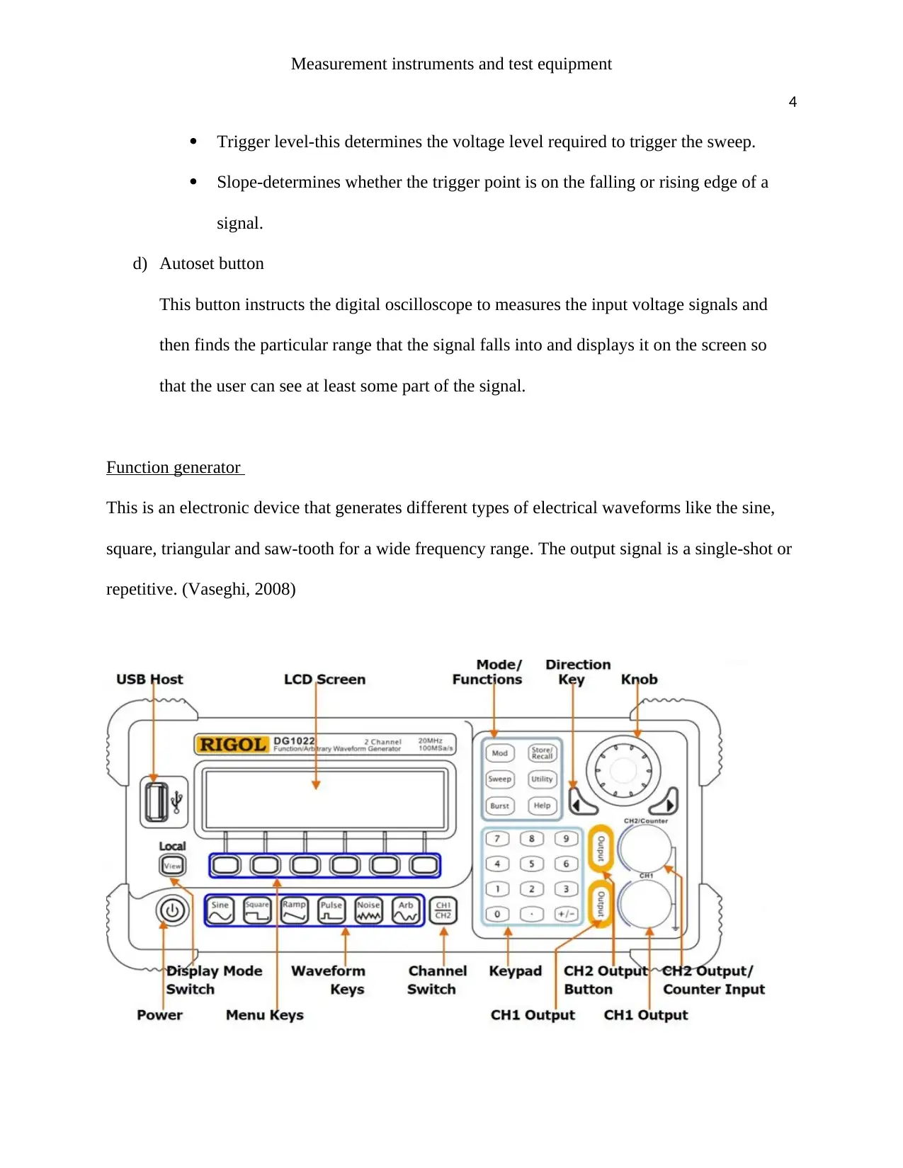
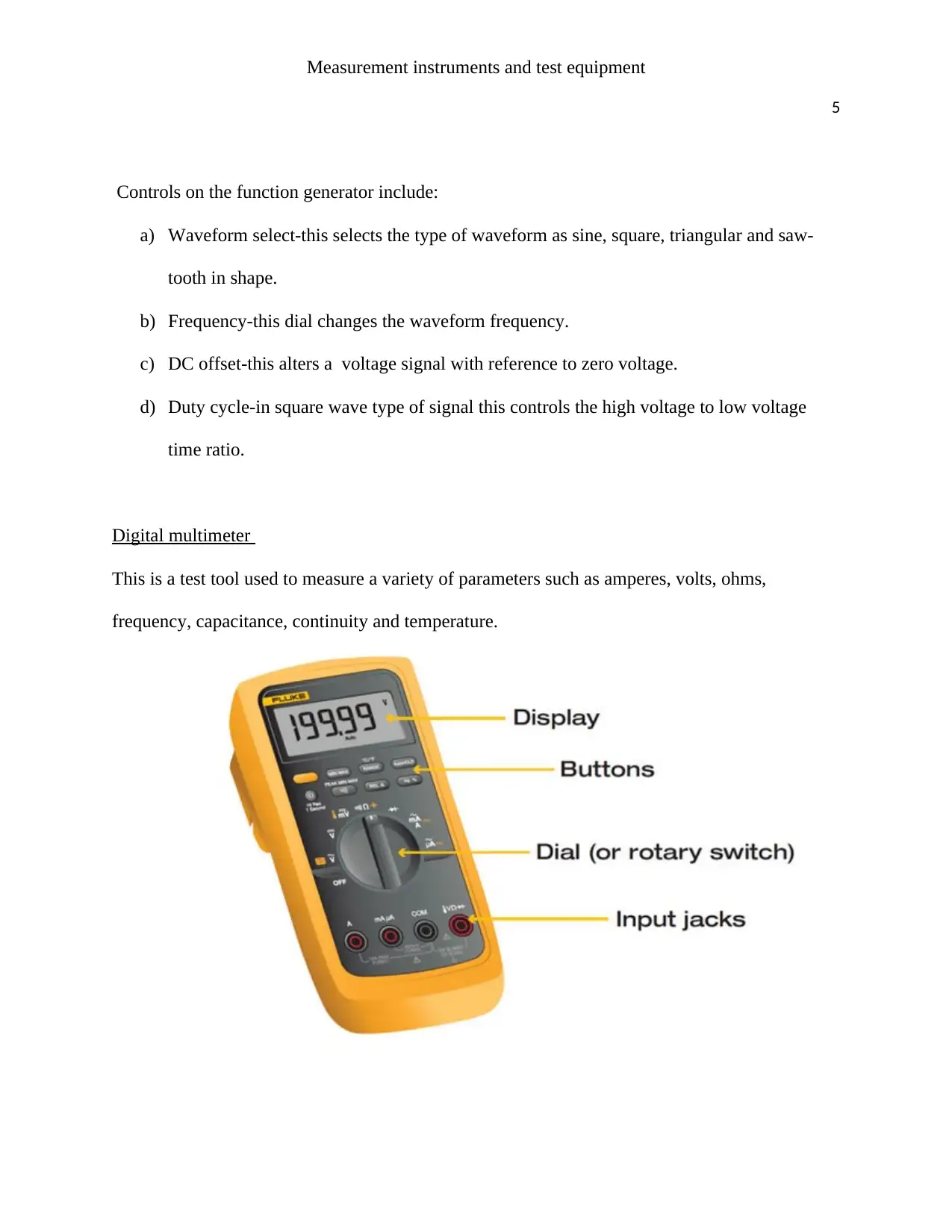
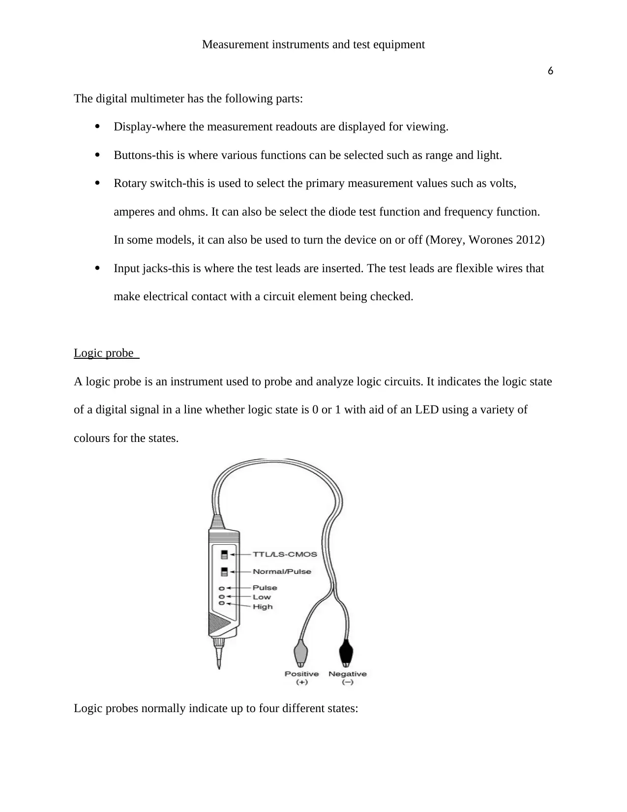
This assignment delves into the world of electronic test equipment. It introduces key instruments such as oscilloscopes, used to display voltage signals over time, function generators for creating different waveforms, digital multimeters for measuring voltage, current, resistance, and other parameters, and logic probes for analyzing digital circuits. The text provides a basic understanding of each instrument's functionality, components, and applications.
Contribute Materials
Your contribution can guide someone’s learning journey. Share your
documents today.
Running head: Measurement instruments and test equipment
1
Measurement instruments and test equipment
Author
Unit
1
Measurement instruments and test equipment
Author
Unit
Secure Best Marks with AI Grader
Need help grading? Try our AI Grader for instant feedback on your assignments.
Measurement instruments and test equipment
2
Oscilloscope
An oscilloscope is an electronic device displaying images of voltage signals inserted at its inputs
that vary with respect to time. Its functions include design, testing, analyzing and debugging
circuits and in audio and video recording equipment.
The digital oscilloscope has the following sections which have dials and buttons used for a
specific function:
a) Vertical controls.
These controls are responsible for the vertical movement of the waveforms displayed on
the screen.(Hughes, n.d.). The position knob adjusts the position of the waveform
upwards or downwards. The voltage/division control knob is a scaling dial that changes
the size of the waveform displayed on the screen.
Measurement instruments and test equipment
3
An oscilloscope also offers bandwidth limiting capabilities. Too much bandwidth is a
problem when the signal is too noisy. This will cause the oscilloscope to trigger on
multiple rising edges leading to a blurry trace as the instrument will have captured
unwanted elements of the signal. This noise is limited by reducing the bandwidth limit.
Input coupling determines which part of the signal is to be displayed on the screen. With
DC coupling, it is possible to observe large transitions in voltage. When coupling is set to
low or high the trace remains low or high respectively. AC coupling blocks the steady
voltage while allowing variations on the displayed voltage. Ground coupling disconnects
the input voltage signal enabling the position of the reference voltage to be set.(Song, Xu
2008)
b) Horizontal controls
This section comprises of the position dial and the time/division dial. The position dial is
responsible for the horizontal movement of the waveform on the screen. The
time/division dial is a time scale which determines how much time the signal is
displayed.
c) Trigger controls
The trigger dial enables the scope to display changing waveforms in a steady manner on
the display that can be viewed by the user. When the signal matches the trigger setting,
the oscilloscope will generate a trigger and capture the signal. Common settings for edge
triggering are:
Source control-the user can manually select a suitable source of triggering like a
line, external input or either of the two channel inputs.
Measurement instruments and test equipment
4
Trigger level-this determines the voltage level required to trigger the sweep.
Slope-determines whether the trigger point is on the falling or rising edge of a
signal.
d) Autoset button
This button instructs the digital oscilloscope to measures the input voltage signals and
then finds the particular range that the signal falls into and displays it on the screen so
that the user can see at least some part of the signal.
Function generator
This is an electronic device that generates different types of electrical waveforms like the sine,
square, triangular and saw-tooth for a wide frequency range. The output signal is a single-shot or
repetitive. (Vaseghi, 2008)
Secure Best Marks with AI Grader
Need help grading? Try our AI Grader for instant feedback on your assignments.
Measurement instruments and test equipment
5
Controls on the function generator include:
a) Waveform select-this selects the type of waveform as sine, square, triangular and saw-
tooth in shape.
b) Frequency-this dial changes the waveform frequency.
c) DC offset-this alters a voltage signal with reference to zero voltage.
d) Duty cycle-in square wave type of signal this controls the high voltage to low voltage
time ratio.
Digital multimeter
This is a test tool used to measure a variety of parameters such as amperes, volts, ohms,
frequency, capacitance, continuity and temperature.
Measurement instruments and test equipment
6
The digital multimeter has the following parts:
Display-where the measurement readouts are displayed for viewing.
Buttons-this is where various functions can be selected such as range and light.
Rotary switch-this is used to select the primary measurement values such as volts,
amperes and ohms. It can also be select the diode test function and frequency function.
In some models, it can also be used to turn the device on or off (Morey, Worones 2012)
Input jacks-this is where the test leads are inserted. The test leads are flexible wires that
make electrical contact with a circuit element being checked.
Logic probe
A logic probe is an instrument used to probe and analyze logic circuits. It indicates the logic state
of a digital signal in a line whether logic state is 0 or 1 with aid of an LED using a variety of
colours for the states.
Logic probes normally indicate up to four different states:
Measurement instruments and test equipment
7
Logic 1 – if the circuit is at logic 1, the probe lights red.
Logic 0 – if the circuit is at a logic 0, it lights green.
Pulses – when the line active a third colour indicator will illuminate an amber colour.
Line tri-state – this occurs when the output turned off and no real state is defined. In most
cases logic probe indicates this sate by having all the indicators off.
Other logic indicators may have an audible indication of the logic state.
Paraphrase This Document
Need a fresh take? Get an instant paraphrase of this document with our AI Paraphraser
Measurement instruments and test equipment
8
References
XU, B.G. and SONG, A.G., 2007. Embedded Digital Storage Oscilloscope Based on UCOS and
UCGUI [J]. Measurement & Control Technology, 7, p.003.
Worones, J.E. and Morey, T.G., Fluke Corporation, 2012. Digital multimeter having improved
rotary switch assembly. U.S. Patent 8,093,516.
Vaseghi, S.V., 2008. Advanced digital signal processing and noise reduction. John Wiley &
Sons.
Hughes, E. (n.d.). Hughes electrical and electronic technology.
1 out of 8
Your All-in-One AI-Powered Toolkit for Academic Success.
+13062052269
info@desklib.com
Available 24*7 on WhatsApp / Email
Unlock your academic potential
© 2024 | Zucol Services PVT LTD | All rights reserved.