Ask a question from expert
Measurement of Flow Characteristics of Meters and Control Valve
15 Pages2811 Words325 Views
Added on 2019-10-16
Measurement of Flow Characteristics of Meters and Control Valve
Added on 2019-10-16
BookmarkShareRelated Documents
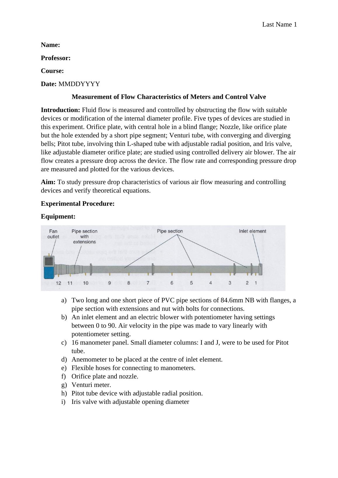
Last Name 1Name: Professor: Course: Date: MMDDYYYYMeasurement of Flow Characteristics of Meters and Control ValveIntroduction: Fluid flow is measured and controlled by obstructing the flow with suitable devices or modification of the internal diameter profile. Five types of devices are studied in this experiment. Orifice plate, with central hole in a blind flange; Nozzle, like orifice plate but the hole extended by a short pipe segment; Venturi tube, with converging and diverging bells; Pitot tube, involving thin L-shaped tube with adjustable radial position, and Iris valve, like adjustable diameter orifice plate; are studied using controlled delivery air blower. The airflow creates a pressure drop across the device. The flow rate and corresponding pressure dropare measured and plotted for the various devices.Aim: To study pressure drop characteristics of various air flow measuring and controlling devices and verify theoretical equations.Experimental Procedure: Equipment:a)Two long and one short piece of PVC pipe sections of 84.6mm NB with flanges, apipe section with extensions and nut with bolts for connections.b)An inlet element and an electric blower with potentiometer having settings between 0 to 90. Air velocity in the pipe was made to vary linearly with potentiometer setting.c)16 manometer panel. Small diameter columns: I and J, were to be used for Pitot tube.d)Anemometer to be placed at the centre of inlet element.e)Flexible hoses for connecting to manometers. f)Orifice plate and nozzle.g)Venturi meter.h)Pitot tube device with adjustable radial position.i)Iris valve with adjustable opening diameter

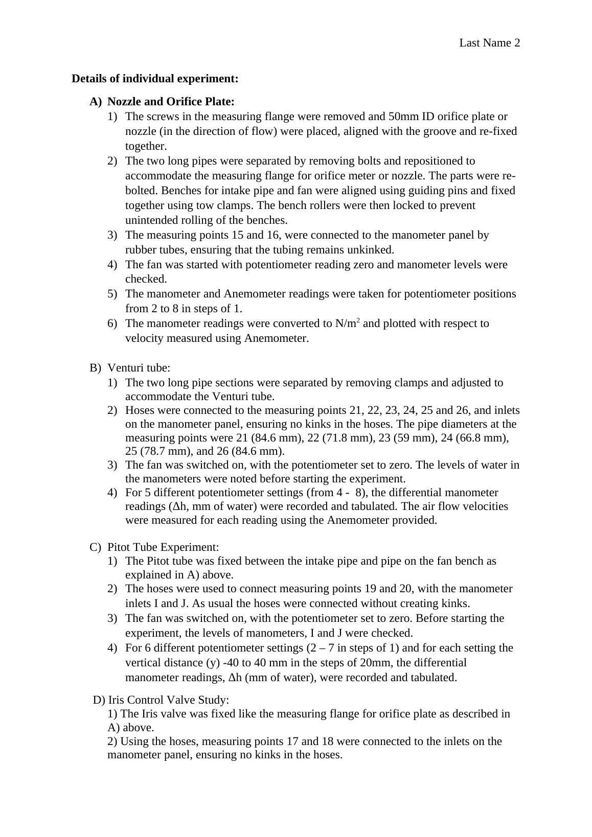
Last Name 2Details of individual experiment:A)Nozzle and Orifice Plate: 1)The screws in the measuring flange were removed and 50mm ID orifice plate or nozzle (in the direction of flow) were placed, aligned with the groove and re-fixedtogether.2)The two long pipes were separated by removing bolts and repositioned to accommodate the measuring flange for orifice meter or nozzle. The parts were re-bolted. Benches for intake pipe and fan were aligned using guiding pins and fixed together using tow clamps. The bench rollers were then locked to prevent unintended rolling of the benches.3)The measuring points 15 and 16, were connected to the manometer panel by rubber tubes, ensuring that the tubing remains unkinked.4)The fan was started with potentiometer reading zero and manometer levels were checked.5)The manometer and Anemometer readings were taken for potentiometer positions from 2 to 8 in steps of 1.6)The manometer readings were converted to N/m2 and plotted with respect to velocity measured using Anemometer. B)Venturi tube:1)The two long pipe sections were separated by removing clamps and adjusted to accommodate the Venturi tube.2)Hoses were connected to the measuring points 21, 22, 23, 24, 25 and 26, and inletson the manometer panel, ensuring no kinks in the hoses. The pipe diameters at the measuring points were 21 (84.6 mm), 22 (71.8 mm), 23 (59 mm), 24 (66.8 mm), 25 (78.7 mm), and 26 (84.6 mm).3)The fan was switched on, with the potentiometer set to zero. The levels of water inthe manometers were noted before starting the experiment. 4)For 5 different potentiometer settings (from 4 - 8), the differential manometer readings (Δh, mm of water) were recorded and tabulated. The air flow velocities were measured for each reading using the Anemometer provided. C)Pitot Tube Experiment:1)The Pitot tube was fixed between the intake pipe and pipe on the fan bench as explained in A) above.2)The hoses were used to connect measuring points 19 and 20, with the manometer inlets I and J. As usual the hoses were connected without creating kinks.3)The fan was switched on, with the potentiometer set to zero. Before starting the experiment, the levels of manometers, I and J were checked. 4)For 6 different potentiometer settings (2 – 7 in steps of 1) and for each setting the vertical distance (y) -40 to 40 mm in the steps of 20mm, the differential manometer readings, Δh (mm of water), were recorded and tabulated. D) Iris Control Valve Study:1) The Iris valve was fixed like the measuring flange for orifice plate as described in A) above.2) Using the hoses, measuring points 17 and 18 were connected to the inlets on the manometer panel, ensuring no kinks in the hoses.

Last Name 33) The fan was switched on, with the potentiometer set to zero. The level of water in the manometers was checked before starting the experiment. 4) The blower potentiometer settings from 2 to 6 in steps of 1 were used. For each setting, readings were taken for 6 valve positions from 1 to 6. The readings were recorded and tabulated.

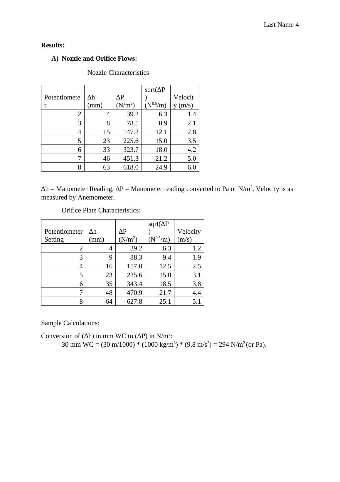
Last Name 4Results:A)Nozzle and Orifice Flows:Nozzle CharacteristicsPotentiometer∆h (mm)∆P (N/m2)sqrt(∆P) (N0.5/m)Velocity (m/s)2439.26.31.43878.58.92.1415147.212.12.8523225.615.03.5633323.718.04.2746451.321.25.0863618.024.96.0∆h = Manometer Reading, ∆P = Manometer reading converted to Pa or N/m2, Velocity is as measured by Anemometer.Orifice Plate Characteristics:Potentiometer Setting∆h (mm)∆P (N/m2)sqrt(∆P)(N0.5/m)Velocity(m/s)2439.26.31.23988.39.41.9416157.012.52.5523225.615.03.1635343.418.53.8748470.921.74.4864627.825.15.1Sample Calculations:Conversion of (∆h) in mm WC to (∆P) in N/m2:30 mm WC = (30 m/1000) * (1000 kg/m3) * (9.8 m/s2) = 294 N/m2 (or Pa).

End of preview
Want to access all the pages? Upload your documents or become a member.
Related Documents
Study on Pressure Drop Characteristicslg...
|15
|2857
|185
Experimental Procedurelg...
|7
|1944
|522
Fluid Flow Characteristics of Tubes and Plates in a Gunt Flow Systemlg...
|14
|2226
|144
Measurement of Flow Characteristics of Meters and Control Valvelg...
|10
|2009
|375
Report On Pressure Drop Of Airflowlg...
|11
|1883
|215
Experiment : Friction in Pipeslg...
|20
|1764
|43