Investigation of Flow Characteristics in Air Flow Measurement Devices
VerifiedAdded on 2019/10/16
|10
|2009
|375
Practical Assignment
AI Summary
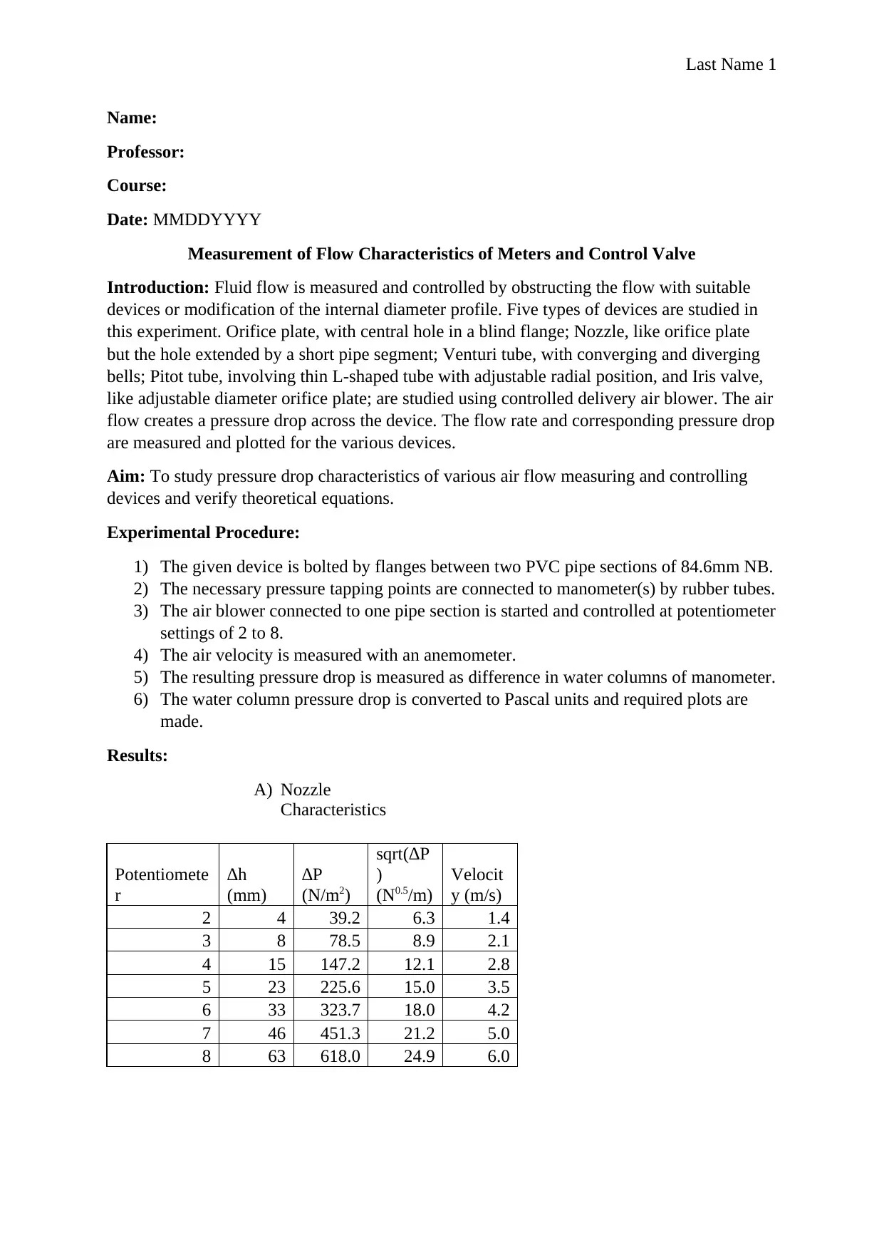
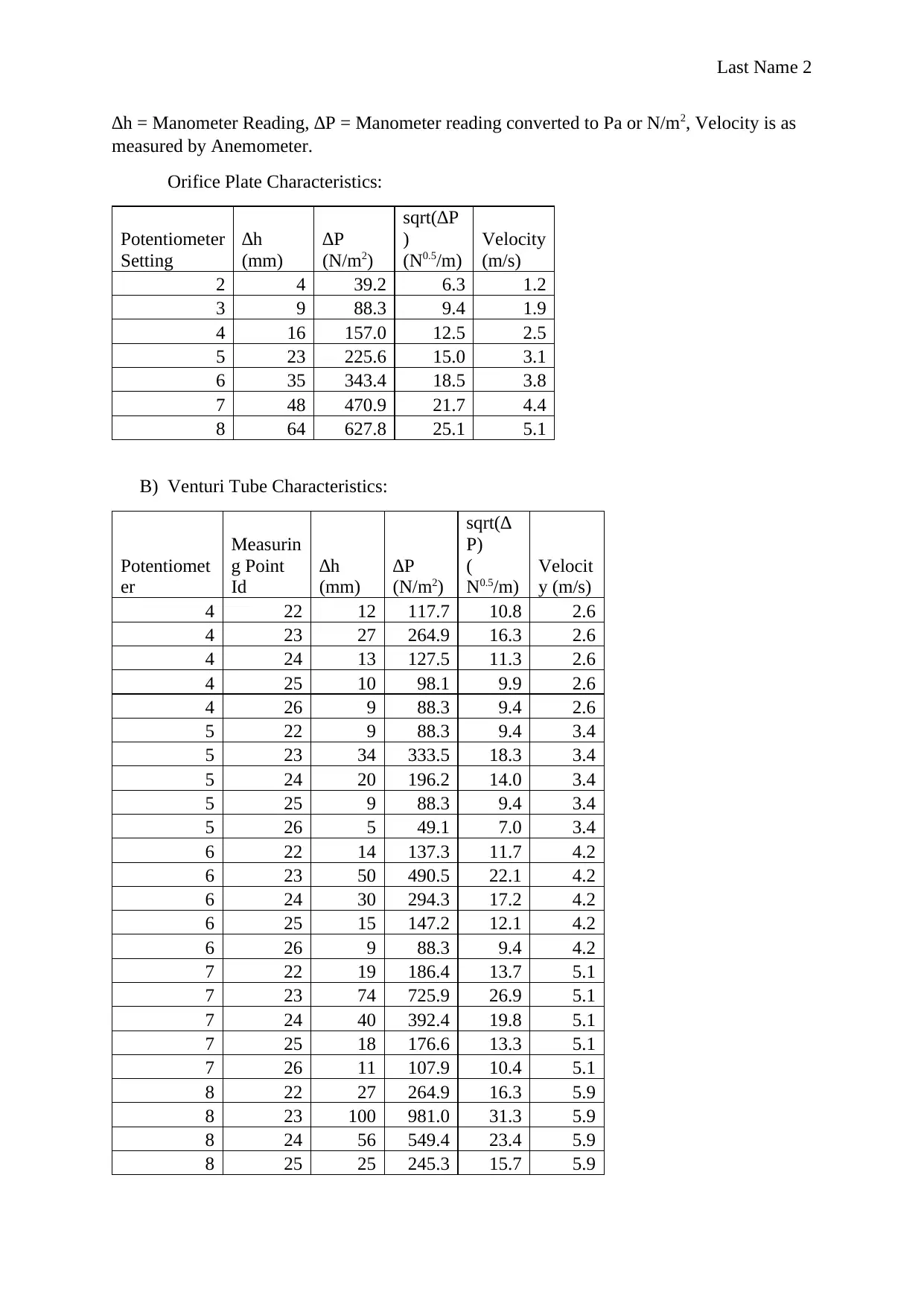
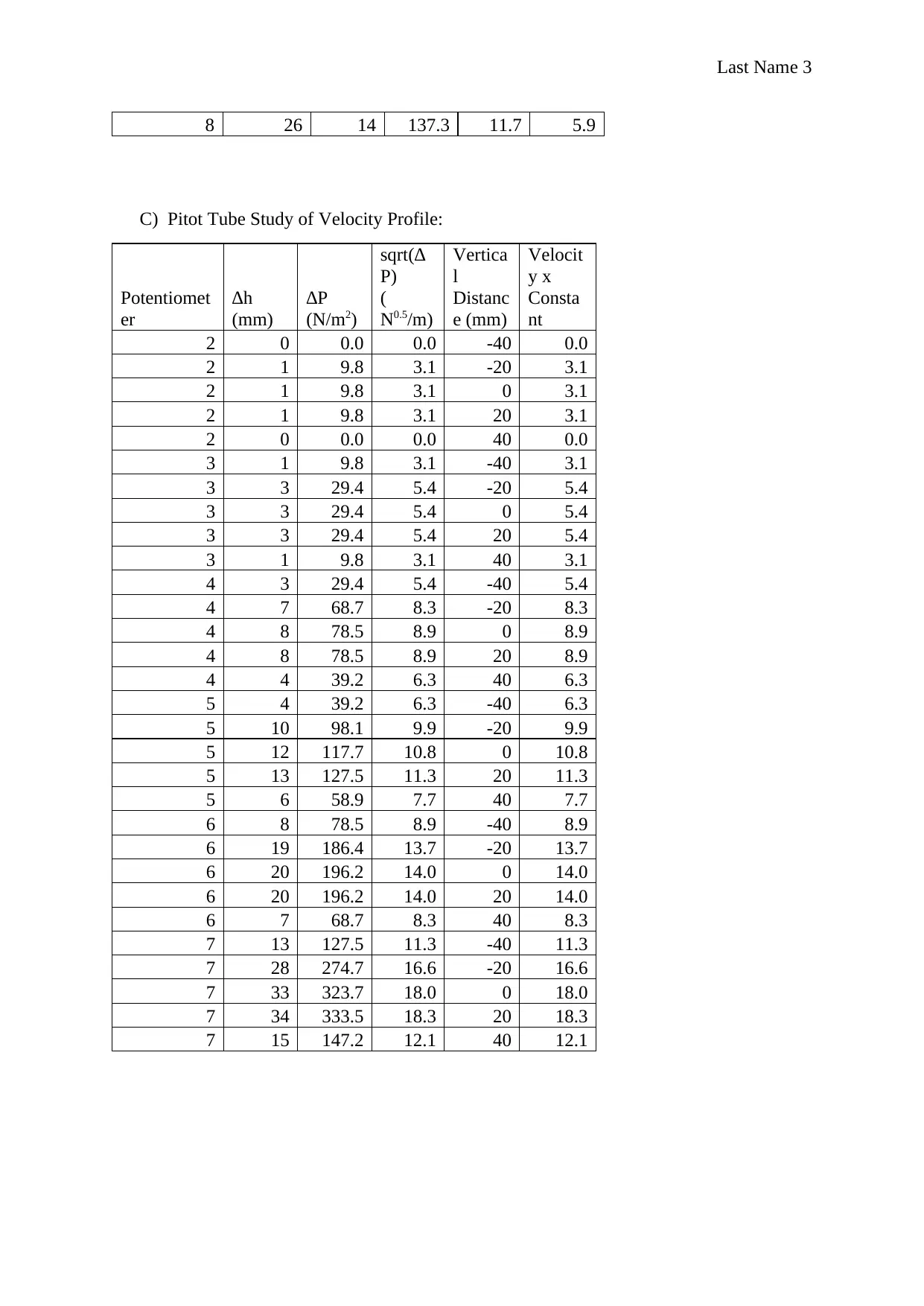
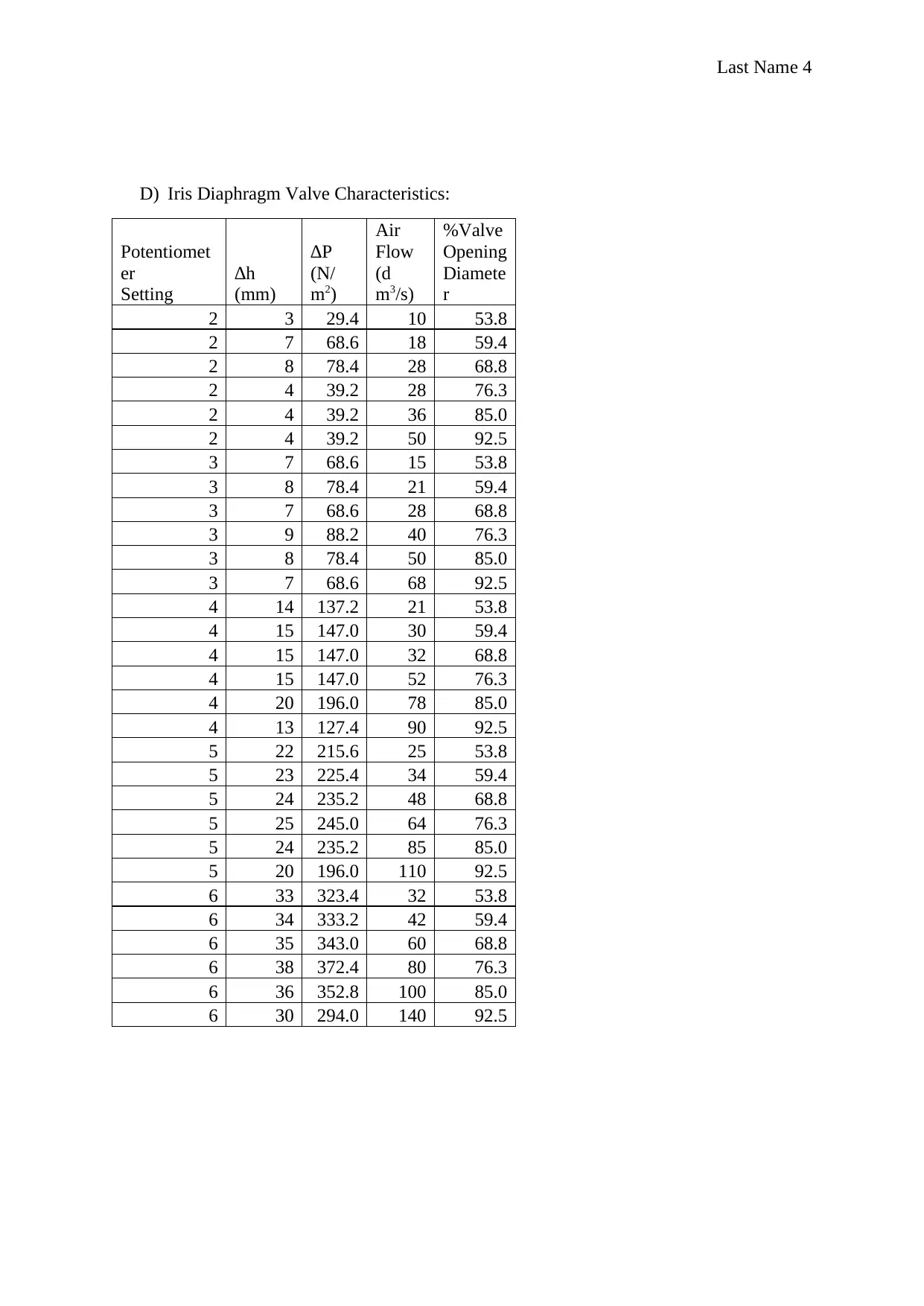
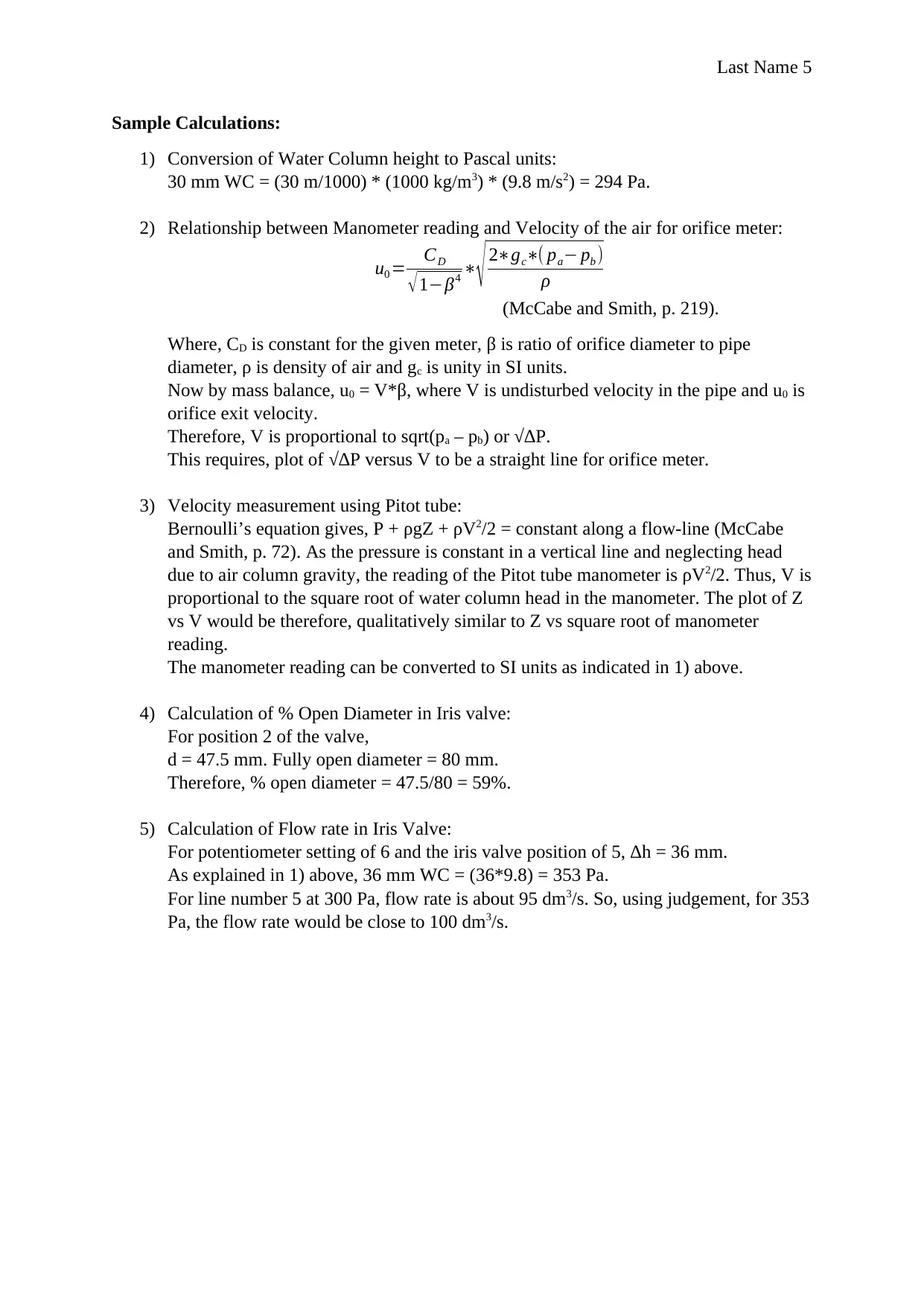
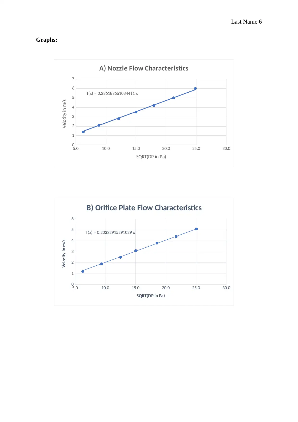
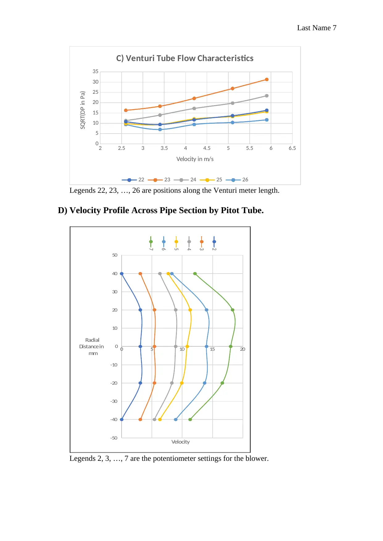
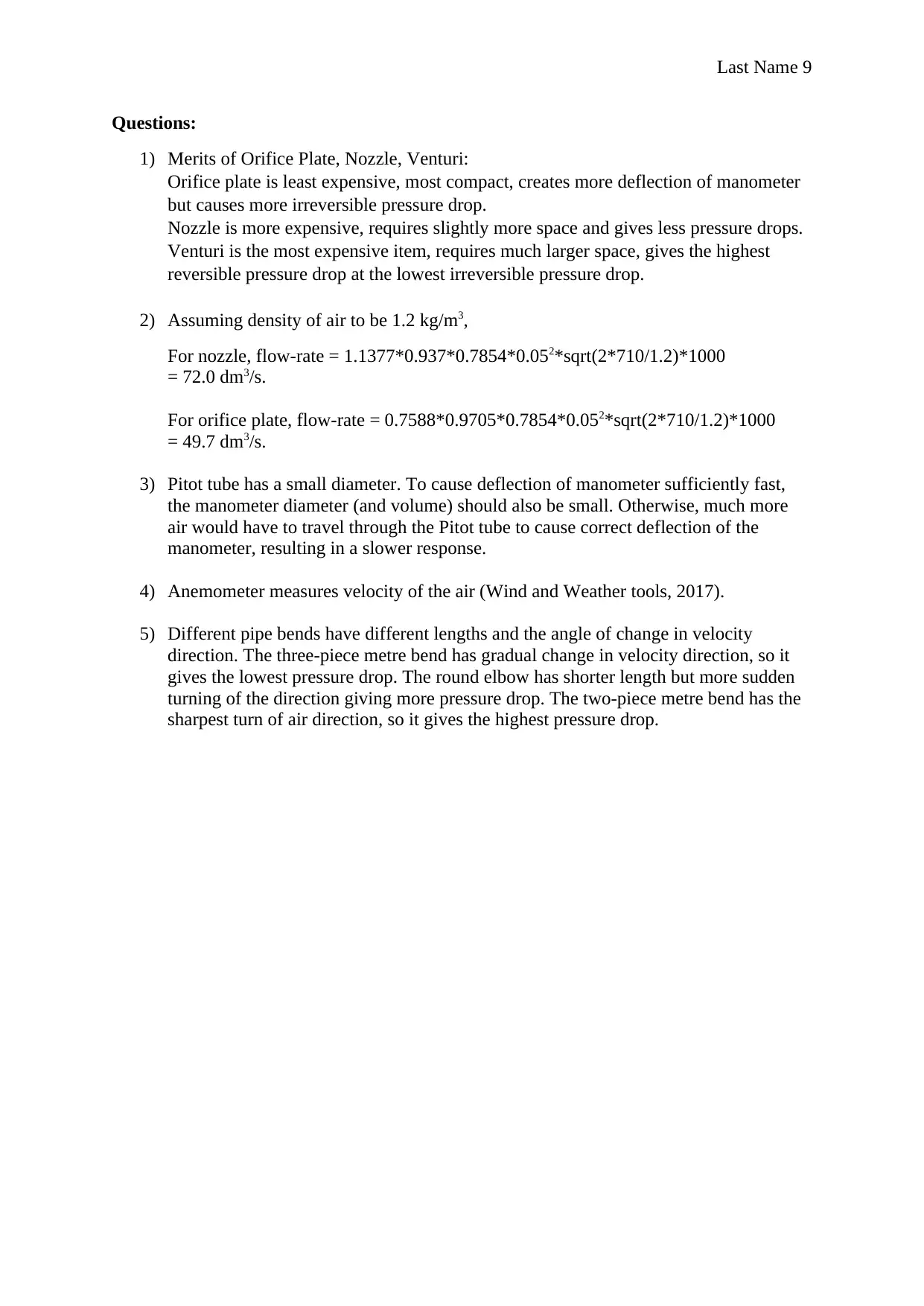
This assignment investigates the flow characteristics of various air flow measuring and controlling devices using a controlled delivery air blower. The experiment studies orifice plates, nozzles, Venturi tubes, Pitot tubes, and Iris valves, measuring the air flow rate and corresponding pressure drop across each device. The procedure involves bolting the devices between PVC pipe sections, connecting pressure tapping points to manometers, and measuring air velocity with an anemometer. Results are presented for each device, including tables of potentiometer settings, manometer readings, calculated pressure drops, and velocities. Sample calculations are provided for converting water column height to Pascal units and determining flow rates. The discussion section analyzes the characteristics of each device, and the conclusion confirms the theoretical equations. The assignment also includes questions on the merits of each device, flow rate calculations, and the impact of Pitot tube diameter and pipe bends on pressure drop. The assignment aims to verify theoretical equations and analyze the performance of these devices in air flow measurement.
1 out of 10
Related Documents


Your All-in-One AI-Powered Toolkit for Academic Success.
+13062052269
info@desklib.com
Available 24*7 on WhatsApp / Email
![[object Object]](/_next/static/media/star-bottom.7253800d.svg)
Copyright © 2020–2026 A2Z Services. All Rights Reserved. Developed and managed by ZUCOL.