Mechanical Design and Development of Pressure Vessels: Analysis Report
VerifiedAdded on 2023/04/21
|29
|4365
|177
Report
AI Summary
This report investigates the mechanical design and development of pressure vessels, focusing on materials like aluminum, steel alloys, and composite materials to enhance performance and reduce weight. It explores burst pressure, mechanical behavior, impact, and compression after impact of filament wound vessels, considering warm and development coefficients. The study delves into impact testing methods, including plate-on-plate tests, and discusses the importance of pressure vessel design for storing compressed natural gas (CNG). The report covers different types of pressure vessels, manufacturing processes for composite materials, and finite element analysis using Abaqus 6.5 FEM package. It examines the properties of materials such as carbon/epoxy towpregs and high-density polyethylene (HDPE), along with the application of contact laws, indentation laws, and velocity measurement techniques to predict the mechanical behavior of pressure vessels. The study emphasizes the significance of pressure vessels in various applications and the need for advanced materials and analysis techniques to ensure safety and efficiency.

MECHANICAL DESIGN AND DEVELOPMENT
By Name
Course
Instructor
Institution
Location
Date
By Name
Course
Instructor
Institution
Location
Date
Paraphrase This Document
Need a fresh take? Get an instant paraphrase of this document with our AI Paraphraser
Abstract
Pressure Vessels are normally used in different applications that are indispensable including
automobile, aerospace, vehicles that are used in the underwater, chemical engineering among
other applications. The pressure vessels that are used in the industries are normally made of
ancient metals like aluminum and steel alloys. This is because the weight of the pressure vessel
will affect to great extend the performance and range of operation. In order to have a better
performance, weight can be effectively reduced in the structure of the shell. The composite
materials are therefore used to increase the strength of the material. The study aims to research
on the burst pressure and mechanical behavior of the filament wound. Also, the impact and also
compression after the impact also taken into the consideration. Likewise, it was resolved the
warm and development coefficients for assess their impact on the burst weight of the composite
funnels.
Introduction
Impact Test is utilized to examine dynamic disfigurement and failure methods of materials. Low-
velocity affect systems can be characterized as plate-on-plate, pole on-plate, plate-on rod, or on
the other hand pole on-pole tests. Two kinds of plate-on-plate affect tests have been produced:
wave generation tests and thin-layer high-strain-rate tests. The plate-on-plate tests are
additionally characterized as non- recovery or recuperation tests. The focal point of this article is
on plate-on-plate trial strategies (Raimondo, Iannucci, Robinson and Curtis 2012). Toward the
conclusion of this article, pole on-plate and plate-on-pole tests are quickly inspected. Perception
of plane waves in materials gives a ground-breaking strategy for comprehension and measuring
their dynamic reaction what’s more, failure modes. Plate impact tests are utilized to produce such
plane waves. These examinations give controlled outrageous pressure state stacking conditions,
including one-dimensional pressure pulse propagation. The recuperation designs in plate-on-
plate affect tests are performed with the target of looking at the microstructural changes in the
example after it is exposed to stacking under a uniaxial strain condition. The trials are intended
to accomplish a controlled plane-wave stacking of the examples (Feng and Aymerich 2014).
Practically speaking, this is constrained by the limited size of the plates utilized, which create
spiral discharge waves. This has the potential for noteworthy commitment to the harm forms by
presenting causes other than the uniaxial stressing of the material.
As the world is experiencing the scarcity of gas and other petroleum fuels, there is need to
ensure that proper preservation is put in place. Most of the power plants, automotive assemblies
use these petroleum products that have been regarded as the potential sources of the pollution
(Vieille, Casado and Bouvet 2013). At present we are in a disturbing zone where we are going
towards the unsettling influence of environmental manageability. Since gaseous petrol is one of
⊘ This is a preview!⊘
Do you want full access?
Subscribe today to unlock all pages.
Trusted by 1+ million students worldwide
the practical, eco-accommodating energizes and additionally dependable for wellbeing for such
activity, which can decrease the deadly causes. The best part to store the packed gaseous petrol
stockpiling is planning of high-weight barrels. The weight vessel is a sort of capacity gadget,
supplies or a shut holder intended for capacity of gases or fluids at a weight which is not quite
the same as the surrounding weight.
It is important to keep the packed petroleum gas at room temperature, and under the filling high
weight in the weight vessel or tank. High-weight stockpiling tank must withstand and split at the
surface or without spillage and additionally greatest weight like a 20MP i.e. Weakness stack
cycle and burst weight. It happens amid refilling of capacity weight vessel. It is the most
imperative high-weight vessel. It ought to keep up high-weight snugness with flame safety.
Capacity weight for compacted flammable gas utilized in different applications; for example,
vehicle and aviation are generally created with help of isotropic material, for example,
Aluminum, steel we are utilizing composite material like carbon fiber, Kevlar fiber and so forth.
Types of Pressure Vessels
The pressure holding capacity of the CNG will normally range from 15N/mm2 to a maximum of
300m2.The application of the pressure can be done either externally or internally on the vessel
itself. In the current set up, there are various types of the pressure vessels that are spherical and
cylindrical whose manufacturing processes have been challenging. Considering that the nature of
the spherical pressure vessels are more compels as compared to the cylindrical, cylindrical
pressure vessels are preferred. The spherical cylinders are however two terms stronger than the
cylindrical ones. The storage pressure vessels have therefore been classified into four categories.
Type 1
Paraphrase This Document
Need a fresh take? Get an instant paraphrase of this document with our AI Paraphraser
This kind of the pressure vessels are completely made of the steel or aluminum metals. The
vessels are very much cost effective and heavy. Their surfaces have coverings of coating and that
properly suit their applications in terms of the temperature regulations.
Type 2
In this type of pressure vessels, the liner of metal is reinforced by the composite wrap around the
surfaces of the structure. Partial all the composite and the liner are equally applied in the making
of the product. They are preferred due to the low weight.
Type 3
In this category, there is full wrapping of the entire tank. The liner used handle little amount of
stress. Although they are preferred to be lighter as compared to the type 2, they are more
expensive.
Type 4
In this kind of the vessel are kept within the plastic tight liner that is reinforced by the composite
material. The whole strength of the tank relies on the reinforcement material that has been used.
(Rafiee and Torabi, 2018).
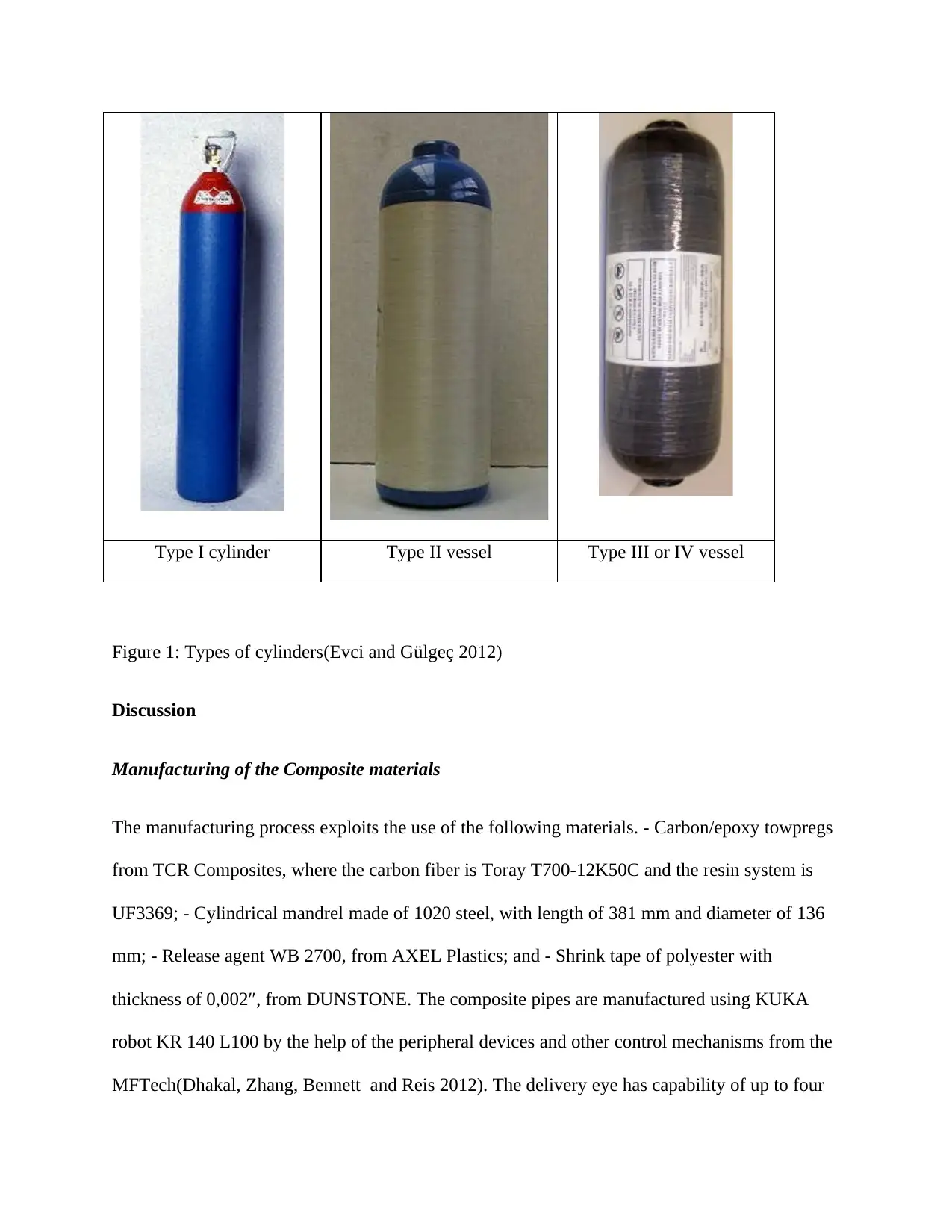
Type I cylinder Type II vessel Type III or IV vessel
Figure 1: Types of cylinders(Evci and Gülgeç 2012)
Discussion
Manufacturing of the Composite materials
The manufacturing process exploits the use of the following materials. - Carbon/epoxy towpregs
from TCR Composites, where the carbon fiber is Toray T700-12K50C and the resin system is
UF3369; - Cylindrical mandrel made of 1020 steel, with length of 381 mm and diameter of 136
mm; - Release agent WB 2700, from AXEL Plastics; and - Shrink tape of polyester with
thickness of 0,002″, from DUNSTONE. The composite pipes are manufactured using KUKA
robot KR 140 L100 by the help of the peripheral devices and other control mechanisms from the
MFTech(Dhakal, Zhang, Bennett and Reis 2012). The delivery eye has capability of up to four
⊘ This is a preview!⊘
Do you want full access?
Subscribe today to unlock all pages.
Trusted by 1+ million students worldwide
pieces of towpregs simultaneously. The design of the subsequent manufacturing of the laminates
gets aided by the use of the CADWind2007.This is a CAD as well as CAM software that used
for the filament winding. This kind of the software has the ability to convert the input data that
has all the parameter into the model of the simulation. The model can therefore be used for
design and manufacturing optimization. The simulated product is post-processed into the KRL
code which is translated into the robot.
Manufacturing of a cylindrical composite pressure vessel made of good grade high-density
polyethylene (HDPE) winded with fiberglass filament.
Raw material and pressure vessel Description
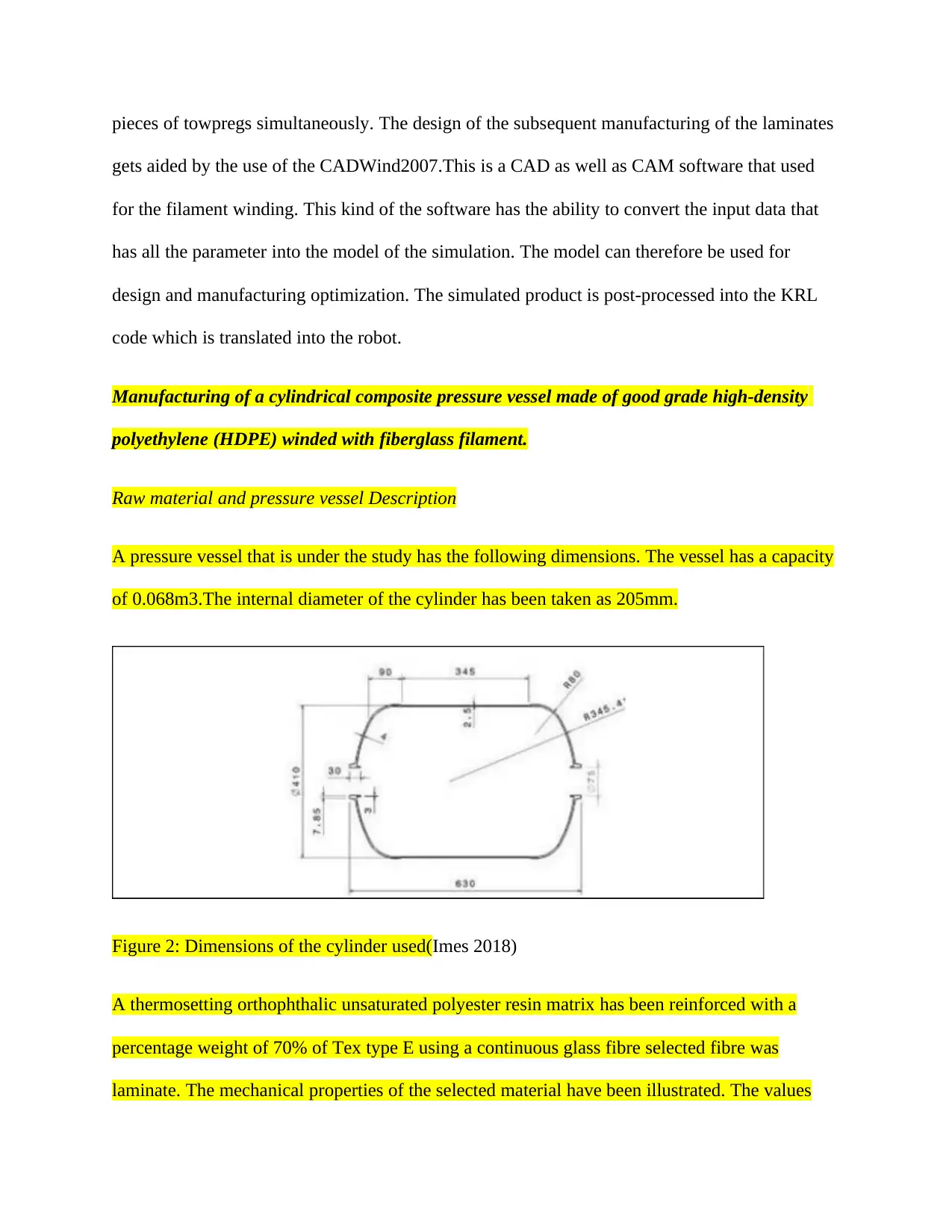
A pressure vessel that is under the study has the following dimensions. The vessel has a capacity
of 0.068m3.The internal diameter of the cylinder has been taken as 205mm.
Figure 2: Dimensions of the cylinder used(Imes 2018)
A thermosetting orthophthalic unsaturated polyester resin matrix has been reinforced with a
percentage weight of 70% of Tex type E using a continuous glass fibre selected fibre was
laminate. The mechanical properties of the selected material have been illustrated. The values
gets aided by the use of the CADWind2007.This is a CAD as well as CAM software that used
for the filament winding. This kind of the software has the ability to convert the input data that
has all the parameter into the model of the simulation. The model can therefore be used for
design and manufacturing optimization. The simulated product is post-processed into the KRL
code which is translated into the robot.
Manufacturing of a cylindrical composite pressure vessel made of good grade high-density
polyethylene (HDPE) winded with fiberglass filament.
Raw material and pressure vessel Description
A pressure vessel that is under the study has the following dimensions. The vessel has a capacity
of 0.068m3.The internal diameter of the cylinder has been taken as 205mm.
Figure 2: Dimensions of the cylinder used(Imes 2018)
A thermosetting orthophthalic unsaturated polyester resin matrix has been reinforced with a
percentage weight of 70% of Tex type E using a continuous glass fibre selected fibre was
laminate. The mechanical properties of the selected material have been illustrated. The values
Paraphrase This Document
Need a fresh take? Get an instant paraphrase of this document with our AI Paraphraser
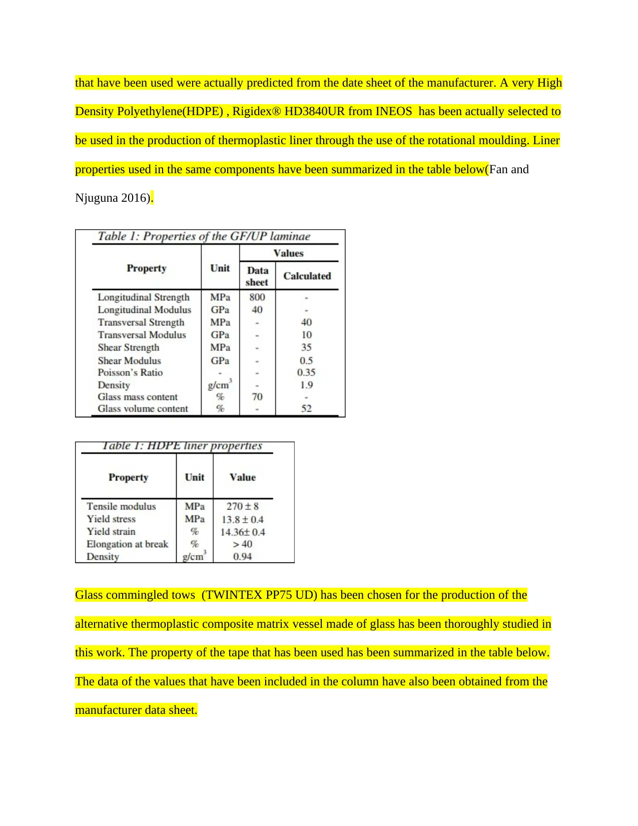
that have been used were actually predicted from the date sheet of the manufacturer. A very High
Density Polyethylene(HDPE) , Rigidex® HD3840UR from INEOS has been actually selected to
be used in the production of thermoplastic liner through the use of the rotational moulding. Liner
properties used in the same components have been summarized in the table below(Fan and
Njuguna 2016).
Glass commingled tows (TWINTEX PP75 UD) has been chosen for the production of the
alternative thermoplastic composite matrix vessel made of glass has been thoroughly studied in
this work. The property of the tape that has been used has been summarized in the table below.
The data of the values that have been included in the column have also been obtained from the
manufacturer data sheet.
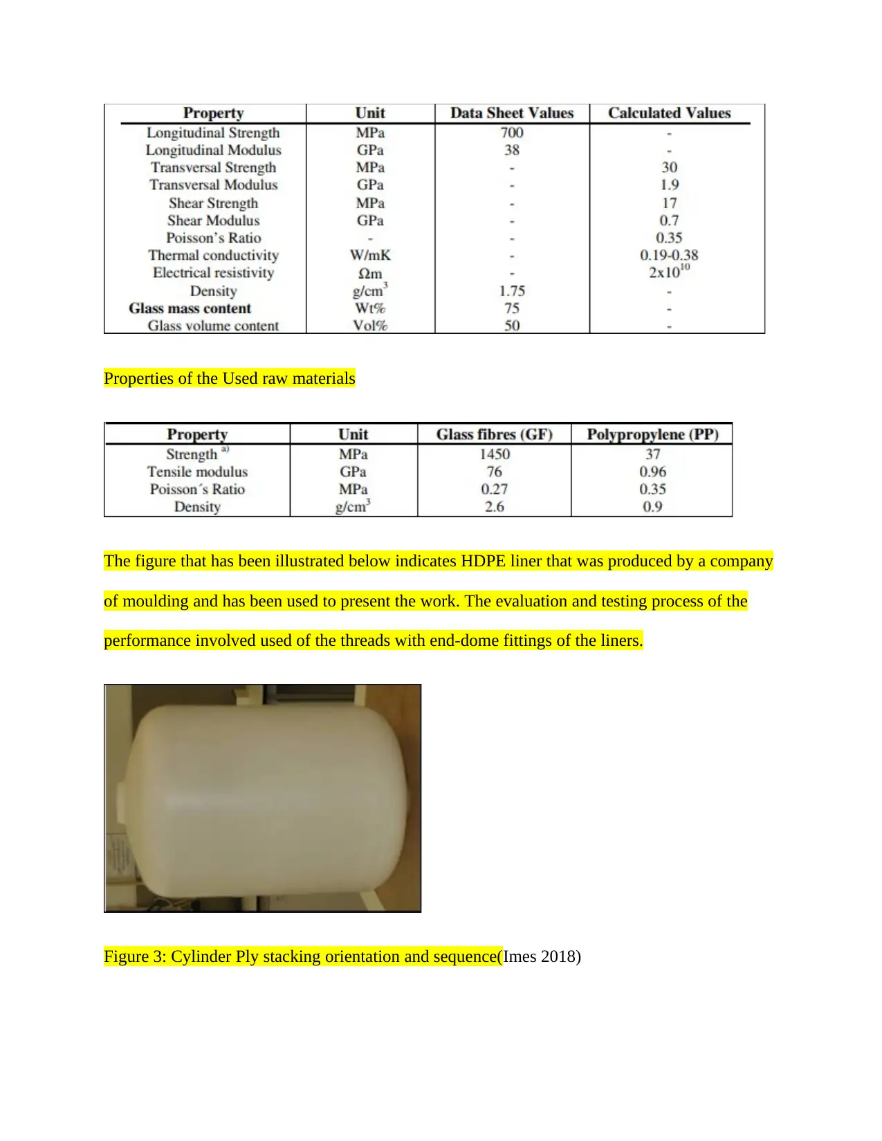
Properties of the Used raw materials
The figure that has been illustrated below indicates HDPE liner that was produced by a company
of moulding and has been used to present the work. The evaluation and testing process of the
performance involved used of the threads with end-dome fittings of the liners.
Figure 3: Cylinder Ply stacking orientation and sequence(Imes 2018)
⊘ This is a preview!⊘
Do you want full access?
Subscribe today to unlock all pages.
Trusted by 1+ million students worldwide
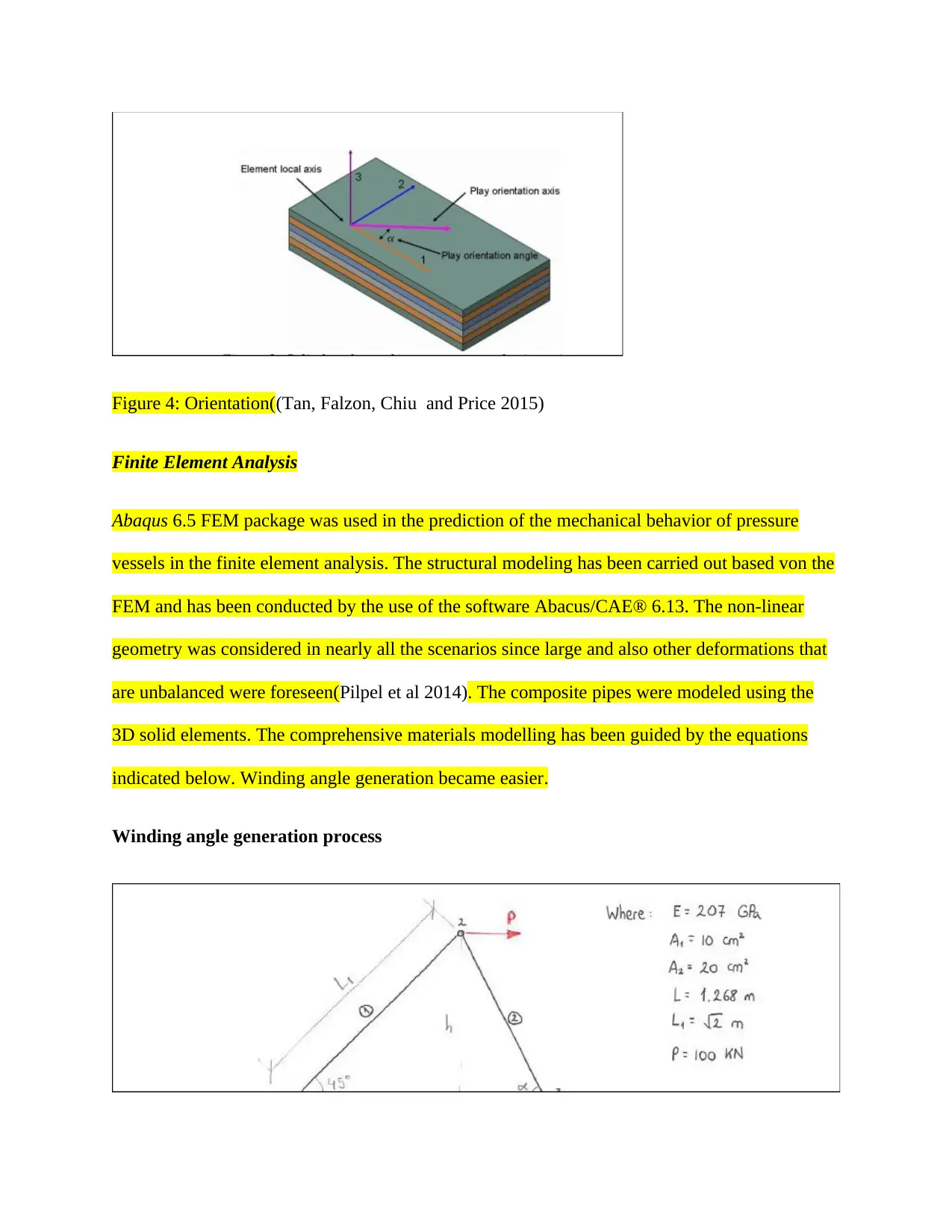
Figure 4: Orientation((Tan, Falzon, Chiu and Price 2015)
Finite Element Analysis
Abaqus 6.5 FEM package was used in the prediction of the mechanical behavior of pressure
vessels in the finite element analysis. The structural modeling has been carried out based von the
FEM and has been conducted by the use of the software Abacus/CAE® 6.13. The non-linear
geometry was considered in nearly all the scenarios since large and also other deformations that
are unbalanced were foreseen(Pilpel et al 2014). The composite pipes were modeled using the
3D solid elements. The comprehensive materials modelling has been guided by the equations
indicated below. Winding angle generation became easier.
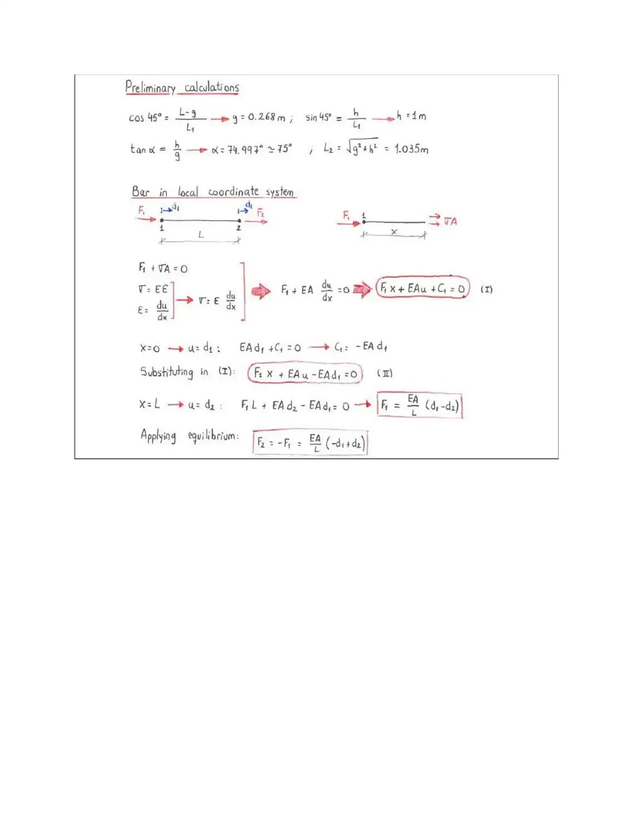
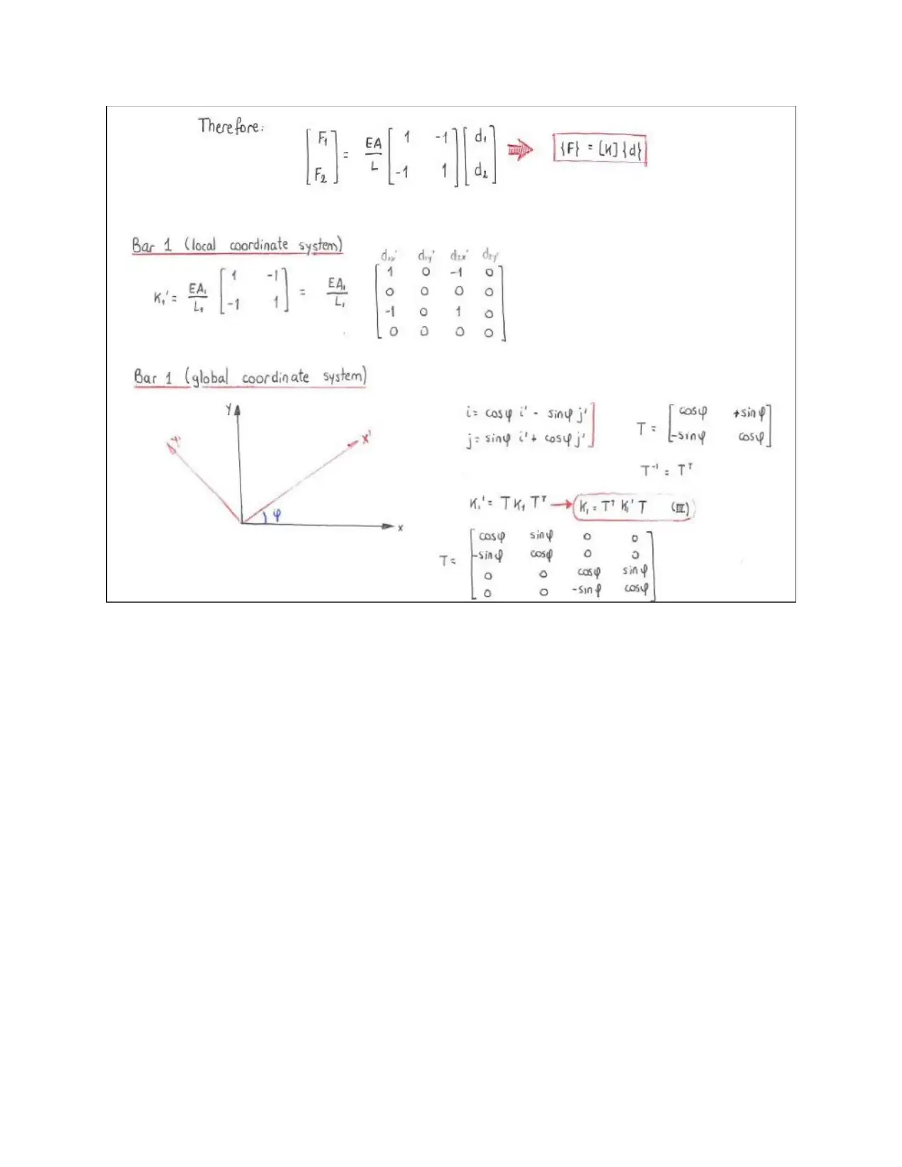
Winding angle generation process
Finite Element Analysis
Abaqus 6.5 FEM package was used in the prediction of the mechanical behavior of pressure
vessels in the finite element analysis. The structural modeling has been carried out based von the
FEM and has been conducted by the use of the software Abacus/CAE® 6.13. The non-linear
geometry was considered in nearly all the scenarios since large and also other deformations that
are unbalanced were foreseen(Pilpel et al 2014). The composite pipes were modeled using the
3D solid elements. The comprehensive materials modelling has been guided by the equations
indicated below. Winding angle generation became easier.
Winding angle generation process
Paraphrase This Document
Need a fresh take? Get an instant paraphrase of this document with our AI Paraphraser
⊘ This is a preview!⊘
Do you want full access?
Subscribe today to unlock all pages.
Trusted by 1+ million students worldwide
1 out of 29
Your All-in-One AI-Powered Toolkit for Academic Success.
+13062052269
info@desklib.com
Available 24*7 on WhatsApp / Email
![[object Object]](/_next/static/media/star-bottom.7253800d.svg)
Unlock your academic potential
Copyright © 2020–2026 A2Z Services. All Rights Reserved. Developed and managed by ZUCOL.