Project: Development of a PWM-Based DC Motor Speed Controller
VerifiedAdded on 2020/02/24
|9
|1822
|381
Project
AI Summary
This project report details the development of a Pulse Width Modulation (PWM)-based DC motor speed controller. The project focuses on controlling the speed of a DC motor using an AT89S52 microcontroller, an L293D IC for motor driving, and infrared sensors for speed measurement. The report covers the project background, objectives, the student's area of work, responsibilities, and the engineering knowledge applied, including the use of PWM, power supply design, and rectifier circuits. The student encountered and solved the issue of voltage incompatibility between the microcontroller and the DC motor by employing a motor driver IC. Furthermore, the project includes plans to enhance the design by integrating an LCD for displaying the motor's speed. The project's review highlights the successful design of a reliable and adaptable speed controller, capable of maintaining a constant speed under varying load conditions. The student contributed significantly to the project through practical knowledge of DC motors and circuit design.

Career Episode 1
Competency
Demonstration Report
Competency
Demonstration Report
Paraphrase This Document
Need a fresh take? Get an instant paraphrase of this document with our AI Paraphraser
CE 1.1 Project Information
Name of the project : Application of PWM for controlling the
speed of DC motor
Location of the project : [PLEASE FILL]
Project Duration : [PLEASE FILL]
Organization : [PLEASE FILL]
Role and Designation during the time : Team Member
CE 1.2 Project Background
CE 1.2.1 Characteristics of the project
In the field of Mechanical Engineering and industrial applications, the DC motor has
founds its use in a significant high rate due to its easy controllability, precise output, and load
characteristics. Controllers developed for the controlling the speed of the Dc motor is essential
for the automation system and the robotic motion of various appliances. I have observed that in
various heavy mechanical devices and automation system, speed control and determining the
constant speed of the DC motor. In this project, I have focused on developing an appropriate
application for controlling the speed of the DC motor for providing precise speed of the DC
motor. Therefore, I have proposed a control system based on Pulse Width Modulation with the
application of various electronic components including sensors, and integrated circuits. I have
used AT89S52 microcontroller for generating the pulse width modulation.
Page 1 of 9
CE 1.2.2 Objectives developed for the project
In this project, I have utilised the technique of PWM (Pulse Width Modulation) for
controlling the accurate speed of the DC motor. The significant aim of the project is to
implement the speed control with the application of microcontroller, L293D Ic, and infrared
sensors for appropriately determining the speed of the DC motor. For the implementation of the
proposed system, I have focused in determining the appropriate process and technique for
implementation for the DC motor speed control. Therefore, for the completion of the project, I
have developed the following objectives:
To develop the hardware implementation for the speed controller of the DC motor;
To implement the appropriate design for counting the speed of the motor with the
application of the sensors;
To employ the technique of PWM for controlling the speed of the DC motor;
To evaluate the working principle for speed controller of the DC motor;
To test and verify the performance and operation of the DC speed controller
developed in this project;
Page 2 of 9
⊘ This is a preview!⊘
Do you want full access?
Subscribe today to unlock all pages.

Trusted by 1+ million students worldwide
CE 1.2.3 My area of work
After determining the hardware components and evaluating the appropriate operation of
the speed controller, I have designed the bread board connection of the hardware elements for
developing the prototype model. I have interconnected all the components on the bread board
and conducted the DC motor run while measuring the speed of the DC motor. I have calculate
the speed of the DC motor with no load and observed the change on the shaft motor. Apart from
that I have conducted the test and analysis of the operations and functionality of the Dc motor
and the speed controller.
CE 1.2.4. Team Members Associated in this Project
Figure 1.1: Team Member Associated in this Project
Page 3 of 9
Paraphrase This Document
Need a fresh take? Get an instant paraphrase of this document with our AI Paraphraser
CE 1.2.5 My responsibilities throughout the project
I had multi facet responsibility in this project for the development and implementation of
the speed controller for the DC motor. In this project, I have appropriately selected hardware
components for operations. I have used L293D IC for providing the trigger to the DC motor. In
addition to that, I have selected the infrared sensors for counting the speed of the DC motor and
show it to the user. Furthermore, for detecting the overloading of the current for the DC motor, I
have used IC 555. After the selection of the hardware element, I have developed the appropriate
block diagram showing the connection between the hardware elements on the bread boards.
Apart from that, I took the extra responsibility in preparing the project report for the
development of the speed controller.
CE 1.3 Distinctive Activity
CE 1.3.1 Comprehending the theory of the project
For the controlling the speed of the DC motor, I have used PWM technique. Furthermore,
I have utilised microcontroller Atmel AT89S52 for generating the appropriate PWM wave for
controlling the speed. I have utilized DC power sources, with variable voltage for controlling the
DC motor speed. I have observed that DC motor takes certain amount of time for obtaining the
maximum speed and takes certain amount of time for getting to zero speed after the switch is off.
Determining the quick succession time between the switching off and on of the DC motor, the
DC motor rotates at a considerably much lower speed. In this project, I have utilized the
technique of PWM for switching on and off the motor with the application of the pulse wave.
Page 4 of 9
CE 1.3.2 Engineering knowledge and skills applied in the project
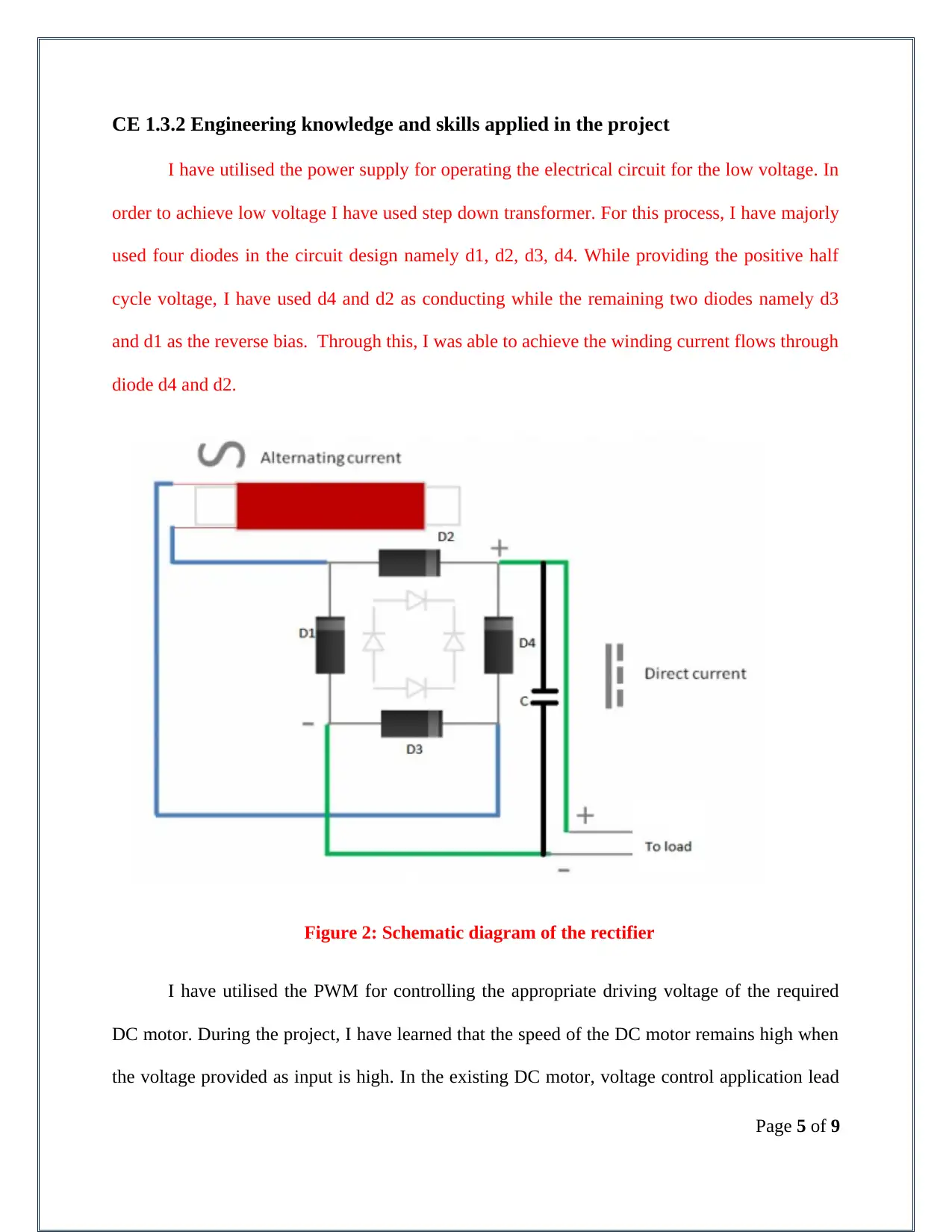
I have utilised the power supply for operating the electrical circuit for the low voltage. In
order to achieve low voltage I have used step down transformer. For this process, I have majorly
used four diodes in the circuit design namely d1, d2, d3, d4. While providing the positive half
cycle voltage, I have used d4 and d2 as conducting while the remaining two diodes namely d3
and d1 as the reverse bias. Through this, I was able to achieve the winding current flows through
diode d4 and d2.
Figure 2: Schematic diagram of the rectifier
I have utilised the PWM for controlling the appropriate driving voltage of the required
DC motor. During the project, I have learned that the speed of the DC motor remains high when
the voltage provided as input is high. In the existing DC motor, voltage control application lead
Page 5 of 9
⊘ This is a preview!⊘
Do you want full access?
Subscribe today to unlock all pages.

Trusted by 1+ million students worldwide
to significant amount of power loss that results in the reducing the speed of the DC motor. I have
further used the DC motor as low pass system while employing the technique of PWM.
Furthermore, I have used step down transformer ranging between 12 V Dc to 230V AC as the
major power sources for the speed controller. Furthermore I have used full wave bridge rectifier
for converting the AC to required DC for the various components used in the circuit. During the
proper implementation of the speed controller, I have used two diodes in reverse bias for the half
cycle of positive voltage. Through this, I was able to obtain flow of current in the same direction.
CE 1.3.3 Accomplishment and task performed
I have used the IC 555 in monostable mode for the development speed controller of the
DC motor. I have utilised the IC 555 for triggering the DC motor when the output is low. I have
further connected the IC in series configuration with the battery. In addition to that, I have
developed the appropriate connection and configuration between the hardware components used
for the DC speed controller.
CE 1.3.4 Identified issues and their solutions
Issue: I have developed the hardware components and connectivity between them. I have
used Atmel AT89S52 microcontroller as the operational module for the system. I have observed
that the Atmel AT89S52 requires significantly small amount of power for operating. On the
other hand, the DC motor requires high voltage for operating. I have faced significant issue,
when I have used the high voltage of the DC motor for powering the microcontroller. The high
voltage has burnt down the microcontroller circuit.
Solution: Therefore, for the eliminating the problem, I have worked and studied various
journals and articles. From the review, I have learnt that in autonomous robotics, motor driving
Page 6 of 9
Paraphrase This Document
Need a fresh take? Get an instant paraphrase of this document with our AI Paraphraser
IC is significantly used. Therefore, in this project I have employed the Motor Driver Ic for
supplying the voltage and current t the microcontroller. I have further used two H bridges for
implementing the circuit and providing input to the microcontroller unit. Through this, I was
successful in providing high power to the Dc motor and low power to the microcontroller for
operation.
CE 1.3.5 Plan to produce creative and innovative work
Through the development and operation of the DC speed controller, I was successful in
controlling and maintaining the constant speed of the DC motor. In order to provide creativeness
and innovation with the project, I have focused on displaying the current speed of the Dc motor
to the user. For this purpose, I have integrated LCD and interfaced in with the microcontroller for
showing the speed of the DC motor. In order to connect the system with the LCD, I have used 2-
220 KΩ resistors, 3- 104 pF Capacitors and 16*2 LCD display. In addition to that, after the
successful implementation and integration of the speed controller, I have used CRO from the
laboratory for testing the speed and performance of the developed prototype model.
CE 1.3.6 Collaborative work
I have focused on providing team work within the project. Before developing the
practical implementation, I have communicated with the team members discussing about the
work plan and procedure that needs to be followed throughout the project. I have ensured proper
information was shared with the team members on a regular basis.
Page 7 of 9
CE 1.4 Project Review
CE 1.4.1 Project Overview
Overview: Through this project, I was able to successfully provide the detailed design of
the speed controller of the DC motor. The developed system was able to provide adaptability,
precision, and reliability in determining the speed and keep the constant speed of the motor based
on the input provided by the user.
Test Results: The sample design for evaluating the performance and operation of the DC
motor showed that the proposed logic and system was able to accurately control the speed of the
motor with high precision and accuracy. Therefore, the DC motor operated with constant speed
inputted by me at any condition of the load factor.
CE 1.4.2 My contribution to work
I have worked as a team members for the implementation of the DC speed controller for
the Dc motor. Through the application of my practical knowledge and detailed information about
the Dc motor, and circuit design process, I was able to obtain considerable success in the project.
Page 8 of 9
⊘ This is a preview!⊘
Do you want full access?
Subscribe today to unlock all pages.

Trusted by 1+ million students worldwide
1 out of 9
Related Documents
Your All-in-One AI-Powered Toolkit for Academic Success.
+13062052269
info@desklib.com
Available 24*7 on WhatsApp / Email
![[object Object]](/_next/static/media/star-bottom.7253800d.svg)
Unlock your academic potential
Copyright © 2020–2025 A2Z Services. All Rights Reserved. Developed and managed by ZUCOL.


