Computer-Aided Design (CAD) in Mechanical Engineering
VerifiedAdded on 2023/04/21
|12
|2518
|371
AI Summary
This article explores the benefits and capabilities of computer-aided design (CAD) in mechanical engineering. It discusses how CAD software can improve accuracy, efficiency, and flexibility in the design process. The article also provides an overview of key features of CAD, such as drawing to scale, convenient layout of drawings, flexibility in organizing drawing information, establishment of drafting standards, and efficient drawing tools. Additionally, it discusses the use of CAD in the design and drawing of jigs, as well as the evaluation of software options for design assistance. Overall, CAD is shown to be a crucial tool for engineers and designers in various industries.
Contribute Materials
Your contribution can guide someone’s learning journey. Share your
documents today.

MECHANICAL ENGINEERING
By Name
Course
Instructor
Institution
Location
Date
By Name
Course
Instructor
Institution
Location
Date
Secure Best Marks with AI Grader
Need help grading? Try our AI Grader for instant feedback on your assignments.
Task 1
Introduction
Computer-aided design commonly known as CAD refers to the technology that involves use of
a computer to aid in the drafting and designing artistic creation or a practical product. In most of
cases, drafting involves the production of engineering drawing or technical work. It is, therefore,
both symbol based and visual communication means. CAD is a very useful tool for artists,
architects, engineers, and draftsmen(Rose, Degen and Melhuish 2014). The current software of
CAD packages ranges from two dimensional or 2D vector based system of drawing to solid and
surface modelers of 3D. The modern version of CAD software allows the drawing to be rotated
in three dimensions(Margonar et al. 2012).
This basically implies that the designer can view the object from any angle that is desired. It is
even possible to do the view from inside while targeting outside. In the space of computer-aided
technology, CAD has become a very crucial technique. This is because of some of the benefits
associated with it like reduced cost of the product development and a highly shortened cycle of
the design. When using CAD the designer can layout and properly develop work on the screen.
The developed work can be printed and saved for future use when edited thus saving time that
would be used for drawing the same product(Nadjmi et al. 2013).
Capabilities Overview
Mostly CAD is employed in the design of machinery and tools which assist in the manufacture
of the components. Also, it is used in the design and drafting of all types of engineering
buildings ranging from the largest industrial and commercial structures to the smallest residential
types. The use is mainly in the physical drawing of 2D components and detailed models of 3D.
The entire processes of the engineering activities employ the use of CAD in the conceptual
design and product layout, dynamic and strength analysis of the assemblies and finally the
definition of the methods of manufacturing of the components.
Key Features
Drawing to scale
CAD has the capability to produce drawings that are very accurate. These drawings are normally
created in 3D or in 2D and taken through the rotation as well. There is normally a possibility of
linking other programmes of the computer to the software of the design(Margonar et al. 2012). In
the case of the drafting that is manual, the determination of the scale is done prior to the exercise
of drawing. The scale basically serves to compare the size of the drawing and that of the actual
object.
Convenient Layout of the drawing
In the case of manual drafting, it is the selection of the sheet that is done first. Normally this
includes title block and pre-printed border. This is then followed by the determination of the
plans of the views, sections, elevations, and details of the drawing. The drawing can then be
started. When CAD is being used, the desired design is first drawn which is called the model in
an environment of drawing known as model space(Pathan 2012). This is then followed with the
creation of the model layout in an environment called paper space. The layout represents a sheet
of the drawing. The layout has general notes, dimensions, title block and finally a border. It also
contains one or several views of the model. The viewpoints of the layout normally act as areas
which are similar to the frames of the windows or pictures(Safdari et al. 2012).

Flexibility in the organization of the information of the drawing
In the case of the CAD, the layers that are present are equivalent to the overlays that are
transparent. Just as for the case of the overlays, the activities such as editing, picture display and
combined or separate printing of layers is possible. These layers can be named so as to allow for
easy tracking of the content and also locking of layers so that alteration cannot be achieved. In
order to comply with the standards of the industries, settings such as line-type, color and line
weight to the layers can be assigned. Layers also allow for the organization of the drawing
objects to allow for plotting.
Establishment of standards of drafting
When drawings are to be done manually, proper accuracy is required in drawing line weights,
line-types, dimensioning among other activities. The application of the standards begins from the
starting point and will be used consistently in the entire process. However, when CAD is to be
used, the conformity with the standards of the company or industry can be achieved through the
creation of the styles that can be applied consistently. It can help in the creation of the
dimensions style, texts, and line types(Mahendran et al. 2016). The establishment of format and
font characteristics including width, height, and even slant can be created by the use of a text
style. These styles, layouts, border information, title block, and layers can be saved by the user.
Use of the templates for drawing helps at the start of a new drawing whose qualities match the
standards of the industry(Taynitskiy, Gubar and Zhitkova 2015).
Efficient drawings
In the case of manual drawing, drawing tools like scales, pencils, erasers among others are used.
Editing of the tasks and repetitive drawing and erasing must be done manually. However, in the
Secure Best Marks with AI Grader
Need help grading? Try our AI Grader for instant feedback on your assignments.
case of the CAD drawing, there is a variety of drawing tools that the user can choose to assist in
the creation of lines, circles among others. It is possible to perform activities like offset, move,
copy, and mirror among others easily (John 2013).
Accurate drawing
When the manual drawing is carried out, there is normally a need to perform careful drawing in
order to ensure correct alignment and size. Manual verification must be carried out on these
specific objects that have been drawn to scale and given proper dimensions as well. When CAD
is used a variety of methods can be applied to fix proper dimensions.
Drawing Modification
Almost all engineering drawings are subject to modification regardless of paperwork or CAD
spaces. When the paperwork is considered for a drawing, the user must use the eraser and then
redraw so as to allow for manual modification or revision on the drawing. The use of CAD,
however, will eliminate manual editing that is also tedious through the provision of several tools
for editing. In the cases where the object is to be copied either in parts or as a whole, the user
does not need to redraw like for the case of the manual drawing(Huang 2012). The erasing can
be done just by the click of a mouse. The objects can be taken through mirroring to obtain a
similar one.
Task Two
Design and Drawing of a jig
CAD software was used in the design and modification of a jig.
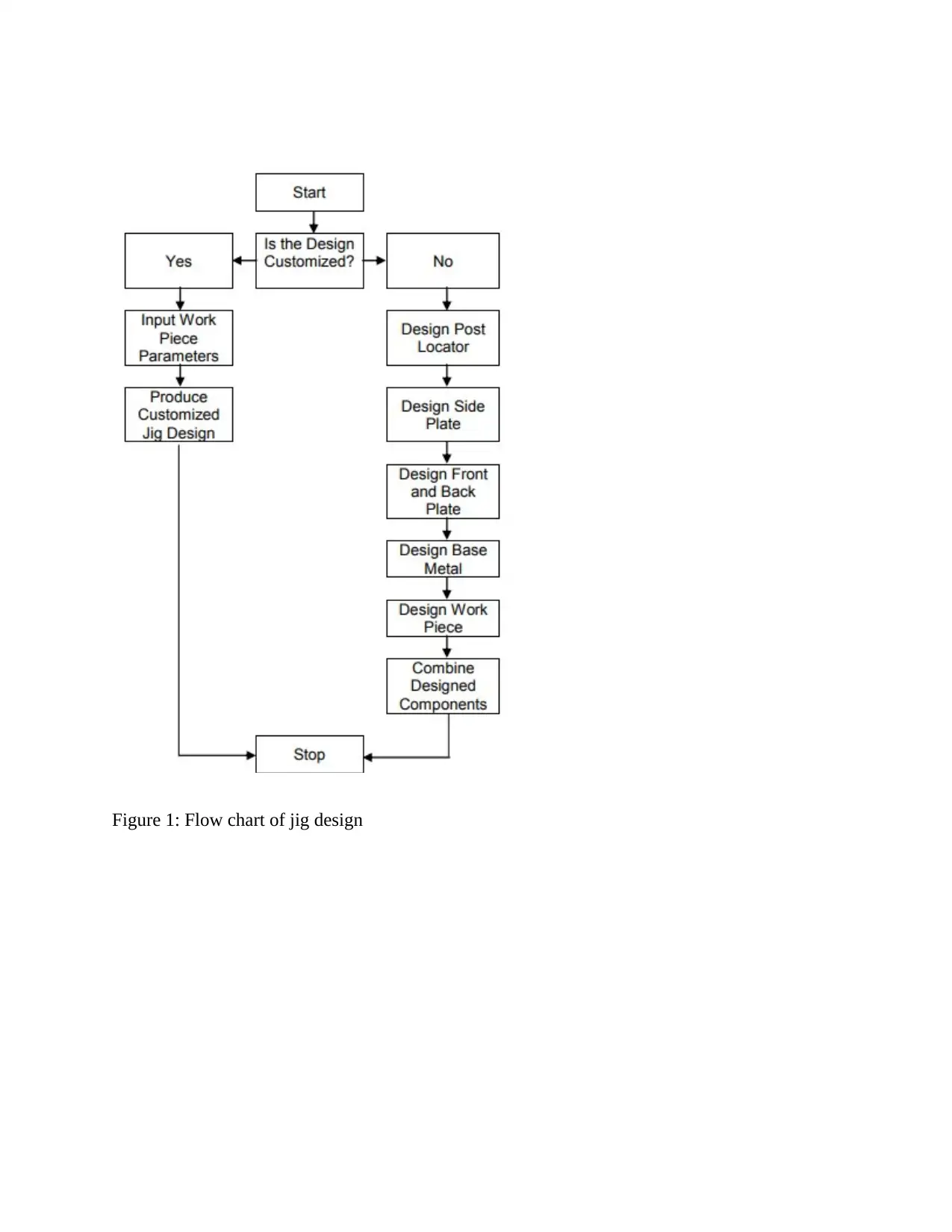
Figure 1: Flow chart of jig design
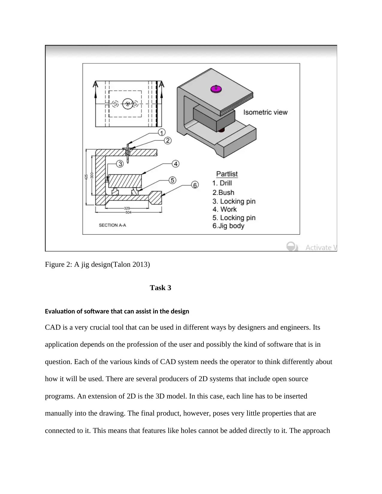
Figure 2: A jig design(Talon 2013)
Task 3
Evaluation of software that can assist in the design
CAD is a very crucial tool that can be used in different ways by designers and engineers. Its
application depends on the profession of the user and possibly the kind of software that is in
question. Each of the various kinds of CAD system needs the operator to think differently about
how it will be used. There are several producers of 2D systems that include open source
programs. An extension of 2D is the 3D model. In this case, each line has to be inserted
manually into the drawing. The final product, however, poses very little properties that are
connected to it. This means that features like holes cannot be added directly to it. The approach
Paraphrase This Document
Need a fresh take? Get an instant paraphrase of this document with our AI Paraphraser
by the operator will, however, be in a similar version of 2D(Jadhav et al. 2012). The 3D model of
CAD allows for the use of the wireframe model to make final views of engineering. The 3D
parametric solid modeling in CAD software like Autodesk Inventor and SolidWorks normally
require the use of design intent. The created objects can be taken through adjustments(Talon
2013).
The modification of the parts will be difficult, simple or impossible depending on the nature of
the originally created part or component. The parametric solid will, therefore, calls for the
consideration of the consequences. Specific programs that incorporate 3D modeling like
AutoCAD are normally generated in a way that is analogous to real-world manipulations.
Cylinders, spheres and other basic forms of three dimensions will have solid volume subtracted
or added from them(Horikoshi et al. 2012). This is the same as if one would be cutting or
assembling from the objects of the real world. The generation of two-dimensional views with
proper elevation cannot be ignored completely. This kind of software does not include tools
which enable motion of the specific parts in either direction.
This consequently limits other activities like setting limits to motions and also identification of
interference between those same parts. AutoCAD inventor will allow for the editing of non-
parametric and parametric geometry(Hakacova et al. 2012). This can be done without the need to
undo a history of the design intent through the functionality of modeling. This capability allows
for inference in the correct relationship between the geometry that is chosen like concentricity
and tangency. Although this will free the engineer from the comprehension of the intent history
of the design, the process of editing will remain to be time-consuming and even involving in
terms of labor. The introduction of Inventors of CAD has simplified and improved interfaces of
the user(Sin et al. 2012).

Conclusion
The use of the computer in engineering design has contributed very significantly to the great
work in the field of science(Zende, Kulkarni and Hutagi 2013.). Accurate drawings that save
time and are presentable as well can be traced back to the use of technical software like
AutoCAD inventor whose technical features are very exploitative and comprehensive.
References
Hakacova, N., Trägårdh-Johansson, E., Wagner, G.S., Maynard, C. and Pahlm, O., 2012.
Computer-based rhythm diagnosis and its possible influence on nonexpert electrocardiogram
readers. Journal of electrocardiology, 45(1), pp.18-22.
Horikoshi, H., Kikuchi, A., Onoguchi, M., Sjöstrand, K., and Edenbrandt, L., 2012. A computer-
aided diagnosis system for bone scintigrams from Japanese patients: the importance of the
training database. Annals of nuclear medicine, 26(8), pp.622-626.
Huang, H.M.E., 2012,. An exploration of computer-based curricula for teaching children volume
measurement concepts. In 36th Conference of the International Group for the Psychology of
Mathematics Education (pp. 315-322).
Jadhav, S., Nikam, K., Gandhi, A., Shinde, N. and Salunkhe, K., 2012. Applications of computer
science in Pharmacy: An overview. National Journal of Physiology, Pharmacy, and
Pharmacology, 2(1), p.1.
John, L.J., 2013. A review of computer-assisted learning in medical undergraduates. Journal of
pharmacology & pharmacotherapeutics, 4(2), p.86.
Mahendran, R., Jeyabaskar, S., Sitharaman, G., Michael, R.D. and Paul, A.V., 2016. Computer-
aided vaccine designing approach against fish pathogens Edwardsiella tarda and Flavobacterium
columnare using bioinformatics software. Drug design, development, and therapy, 10, p.1703.
Margonar, R., Queiroz, T.P., Luvizuto, E.R., Betoni-Júnior, W. and Zocal, E.A., 2012.
Mandibular rehabilitation using immediate implant loading after computer-guided
surgery. Journal of Craniofacial Surgery, 23(2), pp.e129-e132.
Secure Best Marks with AI Grader
Need help grading? Try our AI Grader for instant feedback on your assignments.
Nadjmi, N., Tehranchi, A., Azami, N., Saedi, B. and Mollemans, W., 2013. Comparison of soft-
tissue profiles in Le Fort I osteotomy patients with Dolphin and Maxilim software. American
Journal of Orthodontics and Dentofacial Orthopedics, 144(5), pp.654-662.
Pathan, M.M., 2012. Computer Assisted Language Testing [CALT]: Advantages, Implications,
and Limitations. Research Vistas, 1(4), pp.30-45.
Rose, G., Degen, M., and Melhuish, C., 2014. Networks, interfaces, and computer-generated
images: learning from digital visualizations of urban redevelopment projects. Environment and
Planning D: Society and Space, 32(3), pp.386-403.
Safdari, R., Dargahi, H., Shahmoradi, L. and Nejad, A.F., 2012. Comparing four software based
on ISO 9241 part 10. Journal of medical systems, 36(5), pp.2787-2793.
Sin, L.T., Rahman, W.A.W.A., Rahmat, A.R., Tee, T.T., Bee, S.T. and Chong-Yu, L., 2012.
Computer-aided injection molding process analysis of polyvinyl alcohol-starch green
biodegradable polymer compound. Journal of Manufacturing Processes, 14(1), pp.8-19.
Taynitskiy, V., Gubar, E. and Zhitkova, E., 2015, Structure of optimal control in the model of
propagation of two malicious software. In " Stability and Control Processes" in Memory of VI
Zubov (SCP), 2015 International Conference(pp. 261-264). IEEE.
Talon, M., 2013. A comparative study on computer-aided liquefaction analysis methods. Int.
Journal for Housing Science, 37(2), pp.121-135.
Zende, A.A., Kulkarni, A.V. and Hutagi, A., 2013. Comparative study of analysis and design of
pre-engineered-buildings and conventional frames. IOSR Journal of Mechanical and Civil
Engineering (2013), pp.2278-1684.

1 out of 12
Related Documents
Your All-in-One AI-Powered Toolkit for Academic Success.
+13062052269
info@desklib.com
Available 24*7 on WhatsApp / Email
![[object Object]](/_next/static/media/star-bottom.7253800d.svg)
Unlock your academic potential
© 2024 | Zucol Services PVT LTD | All rights reserved.


