5MA014: Analysis of Joining Methods in Mechanical Engineering
VerifiedAdded on 2023/04/17
By Name
Course
Instructor
Institution
Location
Date
Paraphrase This Document
Introduction
Adhesive bonding is a technique that is used in fastening of the two surfaces together and results in the production of a smooth bond.
This kind of technique normally involves the use of materials like glues, various agents of the plastics, epoxies and other components
that are responsible for bonding through the process of evaporation. There has been a production of weak bonds by glues in the past.
However, the present application of plastic-based agents including “super-glues” that is capable of undergoing a self-curing process
has allowed the existence of the adhesion with strength(Kreindl et al. 2014).
Question One
.The mechanical fastening employs the use of different material components including:
Steel
of the fasteners by their grades. The most common specification includes SAE grades 2, 5, and 8.
Aluminum
Among the most commonly used fasteners, alloys of Aluminium are the least in terms of costs. The typical alloys that are used for the
fastening include 2024-T4 which constitutes rivets, cold-formed bolts and machine screw nuts(Gadakh, Shinde and Khemnar 2013)
Brass
It is preferred for mechanical fastening since it can be worked easily into the required shapes and it possesses adequate strength. Tithe
improvement of the tensile strength is through cold working.
Copper
The fasteners made from copper are preferred because it is resistant to corrosion. Copper is also malleable and has the highest
conductivity of all the metals that are nonprecious.
The process of thermal joining employs processes of welding, brazing, and soldering. This method is only effective on the
homogeneous surface whose melting points are the same. The process of soldering normally employs the use of tin-lead alloy as the
⊘ This is a preview!⊘
Do you want full access?
Subscribe today to unlock all pages.
Trusted by 1+ million students worldwide
silver.
Question Two
Impacts of the mechanism of fastening on the surface of the materials
The application of the mechanical fasteners is common for the case of the bolted joints and riveted joints. This two type of fastening
system is very common for the case of structures of the aircraft where they are known to offer a convenient and rapid method of
assembling large structures from the smaller components. There are a proper understanding and prediction of the load bearing
mechanism of the metallic joints. There are significant penalties when these kinds of fasteners are used in the composite structures. As
per the example is shown below, there is a transfer of load from a composite wing skin to the Aluminium metallic bracket by the use
of a 9-bolt junction. Each of the holes will be subjected to tension when this particular component is in service. This will lead to the
promotion of the damage progression after initiation.
Paraphrase This Document
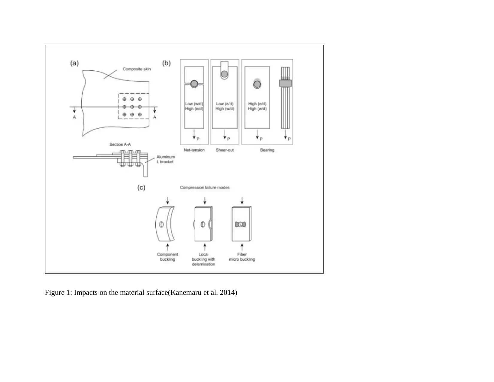
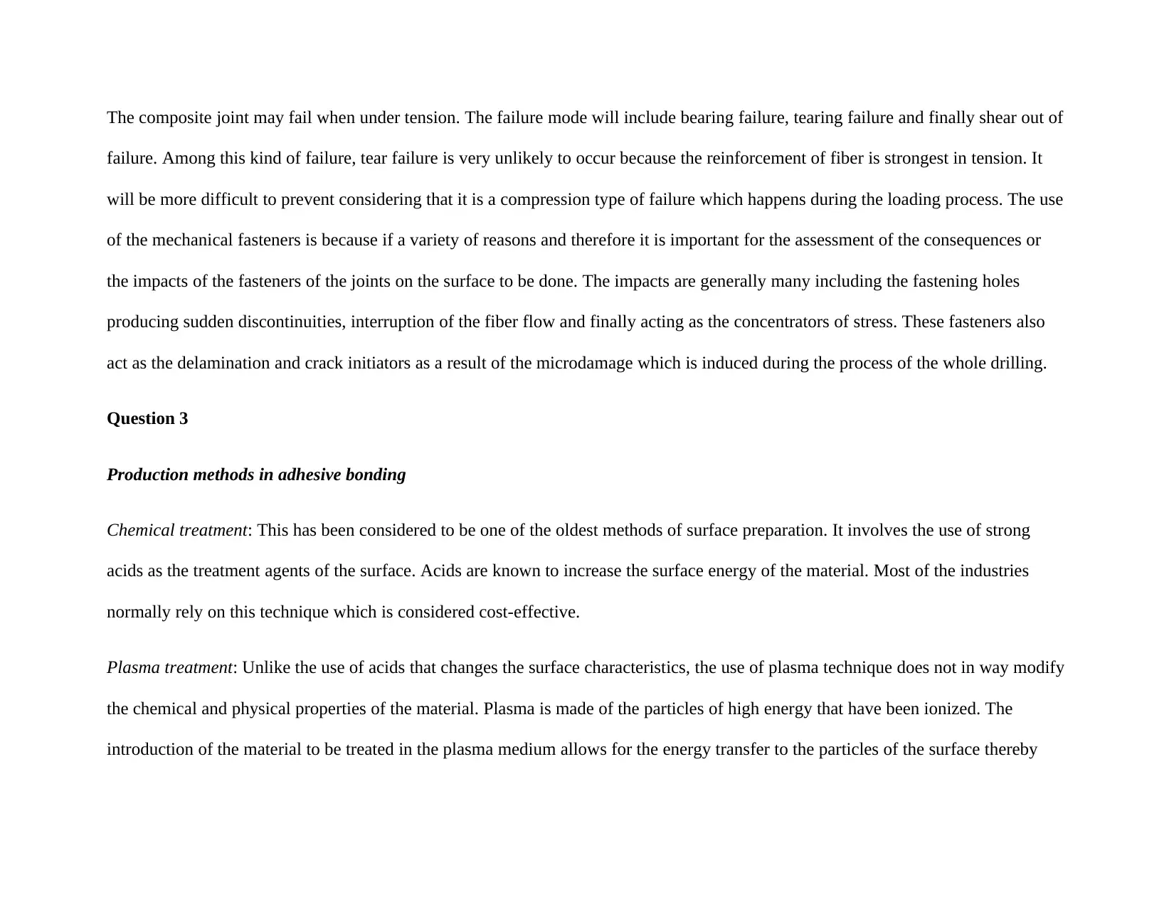
failure. Among this kind of failure, tear failure is very unlikely to occur because the reinforcement of fiber is strongest in tension. It
will be more difficult to prevent considering that it is a compression type of failure which happens during the loading process. The use
of the mechanical fasteners is because if a variety of reasons and therefore it is important for the assessment of the consequences or
the impacts of the fasteners of the joints on the surface to be done. The impacts are generally many including the fastening holes
producing sudden discontinuities, interruption of the fiber flow and finally acting as the concentrators of stress. These fasteners also
act as the delamination and crack initiators as a result of the microdamage which is induced during the process of the whole drilling.
Question 3
Production methods in adhesive bonding
Chemical treatment: This has been considered to be one of the oldest methods of surface preparation. It involves the use of strong
acids as the treatment agents of the surface. Acids are known to increase the surface energy of the material. Most of the industries
normally rely on this technique which is considered cost-effective.
Plasma treatment: Unlike the use of acids that changes the surface characteristics, the use of plasma technique does not in way modify
the chemical and physical properties of the material. Plasma is made of the particles of high energy that have been ionized. The
introduction of the material to be treated in the plasma medium allows for the energy transfer to the particles of the surface thereby
⊘ This is a preview!⊘
Do you want full access?
Subscribe today to unlock all pages.
Trusted by 1+ million students worldwide
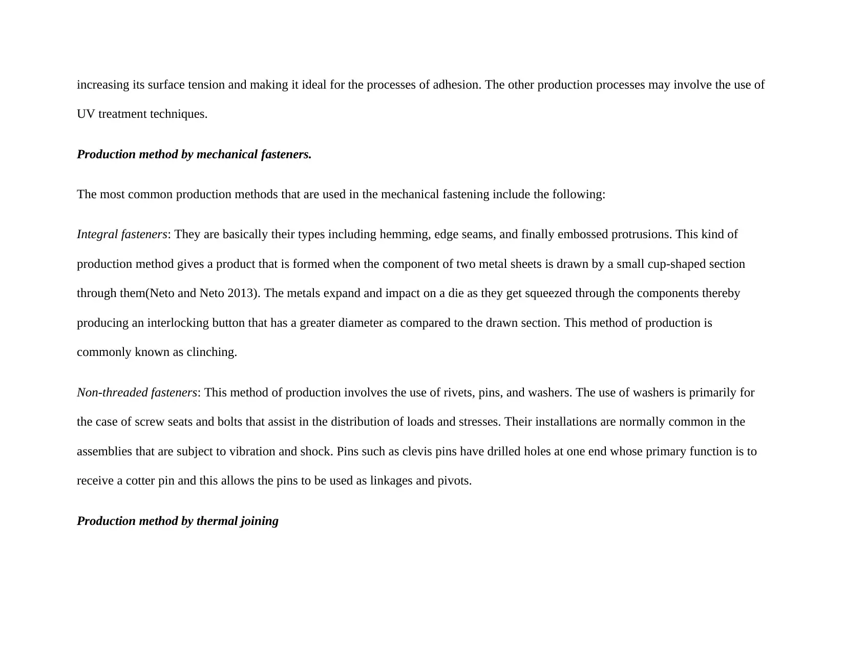
UV treatment techniques.
Production method by mechanical fasteners.
The most common production methods that are used in the mechanical fastening include the following:
Integral fasteners: They are basically their types including hemming, edge seams, and finally embossed protrusions. This kind of
production method gives a product that is formed when the component of two metal sheets is drawn by a small cup-shaped section
through them(Neto and Neto 2013). The metals expand and impact on a die as they get squeezed through the components thereby
producing an interlocking button that has a greater diameter as compared to the drawn section. This method of production is
commonly known as clinching.
Non-threaded fasteners: This method of production involves the use of rivets, pins, and washers. The use of washers is primarily for
the case of screw seats and bolts that assist in the distribution of loads and stresses. Their installations are normally common in the
assemblies that are subject to vibration and shock. Pins such as clevis pins have drilled holes at one end whose primary function is to
receive a cotter pin and this allows the pins to be used as linkages and pivots.
Production method by thermal joining
Paraphrase This Document
and flowing the filler metal into the joint. In most of the case, the filler has a lower melting point than the adjoining components of the
metal.
Question 4
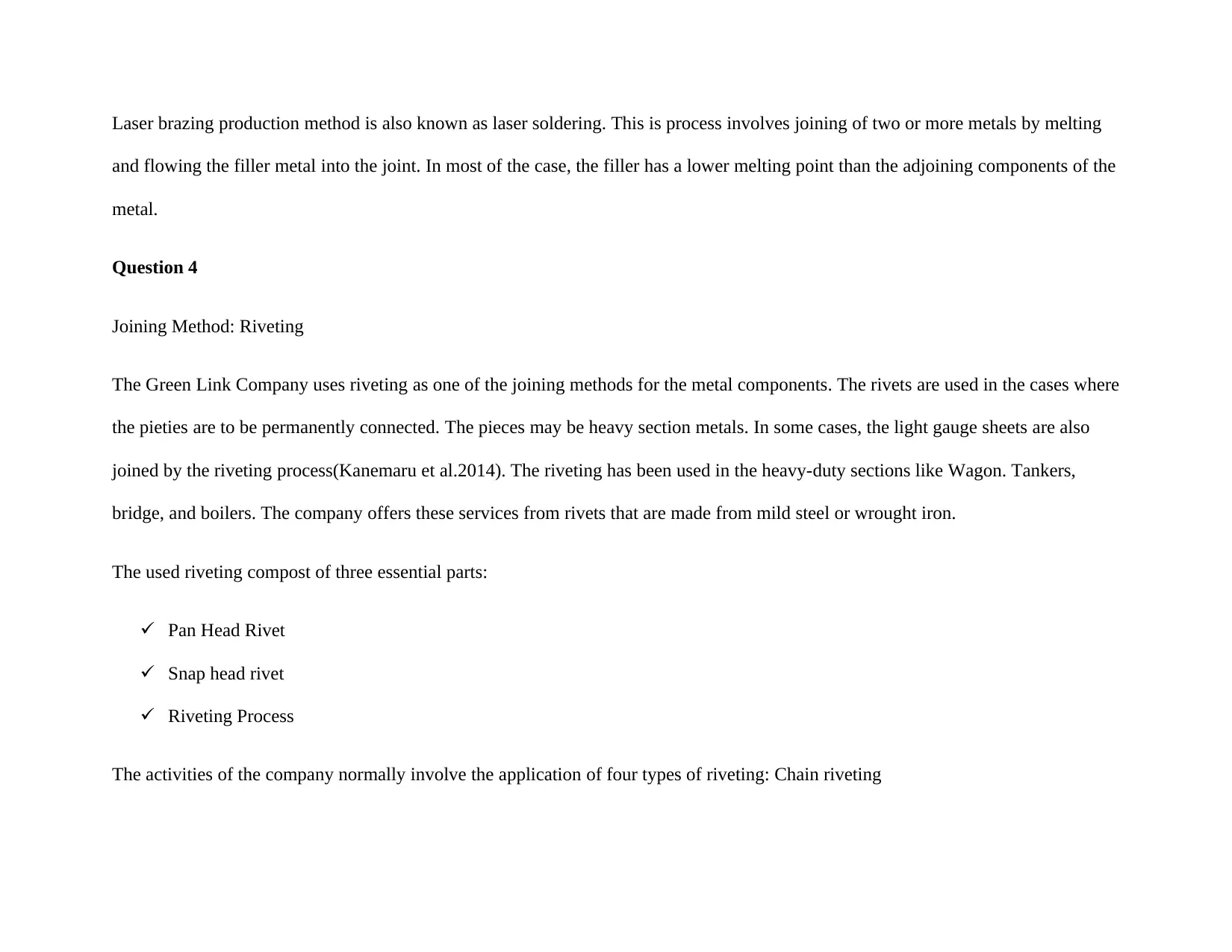
Joining Method: Riveting
The Green Link Company uses riveting as one of the joining methods for the metal components. The rivets are used in the cases where
the pieties are to be permanently connected. The pieces may be heavy section metals. In some cases, the light gauge sheets are also
joined by the riveting process(Kanemaru et al.2014). The riveting has been used in the heavy-duty sections like Wagon. Tankers,
bridge, and boilers. The company offers these services from rivets that are made from mild steel or wrought iron.
The used riveting compost of three essential parts:
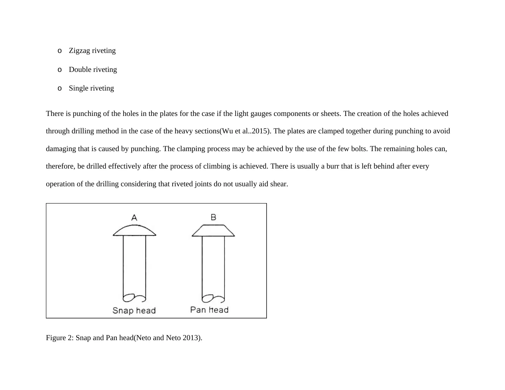
Pan Head Rivet
Snap head rivet
Riveting Process
The activities of the company normally involve the application of four types of riveting: Chain riveting
o Double riveting
o Single riveting
There is punching of the holes in the plates for the case if the light gauges components or sheets. The creation of the holes achieved
through drilling method in the case of the heavy sections(Wu et al..2015). The plates are clamped together during punching to avoid
damaging that is caused by punching. The clamping process may be achieved by the use of the few bolts. The remaining holes can,
therefore, be drilled effectively after the process of climbing is achieved. There is usually a burr that is left behind after every
operation of the drilling considering that riveted joints do not usually aid shear.
Figure 2: Snap and Pan head(Neto and Neto 2013).
⊘ This is a preview!⊘
Do you want full access?
Subscribe today to unlock all pages.
Trusted by 1+ million students worldwide
Part Two (Lab report)
Spot Welding:
Methodology
Requirements
3 pairs of metals including 6061-T6 aluminum, 1018 cold rolled carbon steel and 304 annealed stainless steel.
Specimen sizes: 1” x 4” x 0.032” each.
Paraphrase This Document
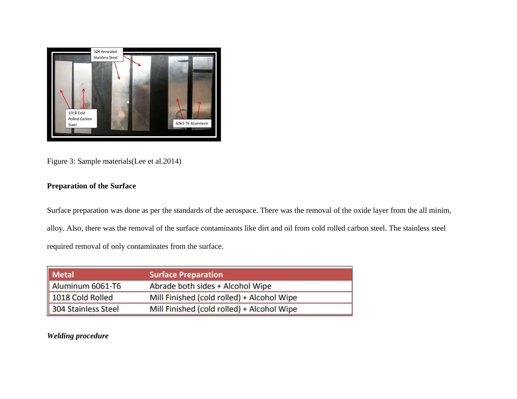
Preparation of the Surface
Surface preparation was done as per the standards of the aerospace. There was the removal of the oxide layer from the all minim,
alloy. Also, there was the removal of the surface contaminants like dirt and oil from cold rolled carbon steel. The stainless steel
required removal of only contaminates from the surface.
Welding procedure
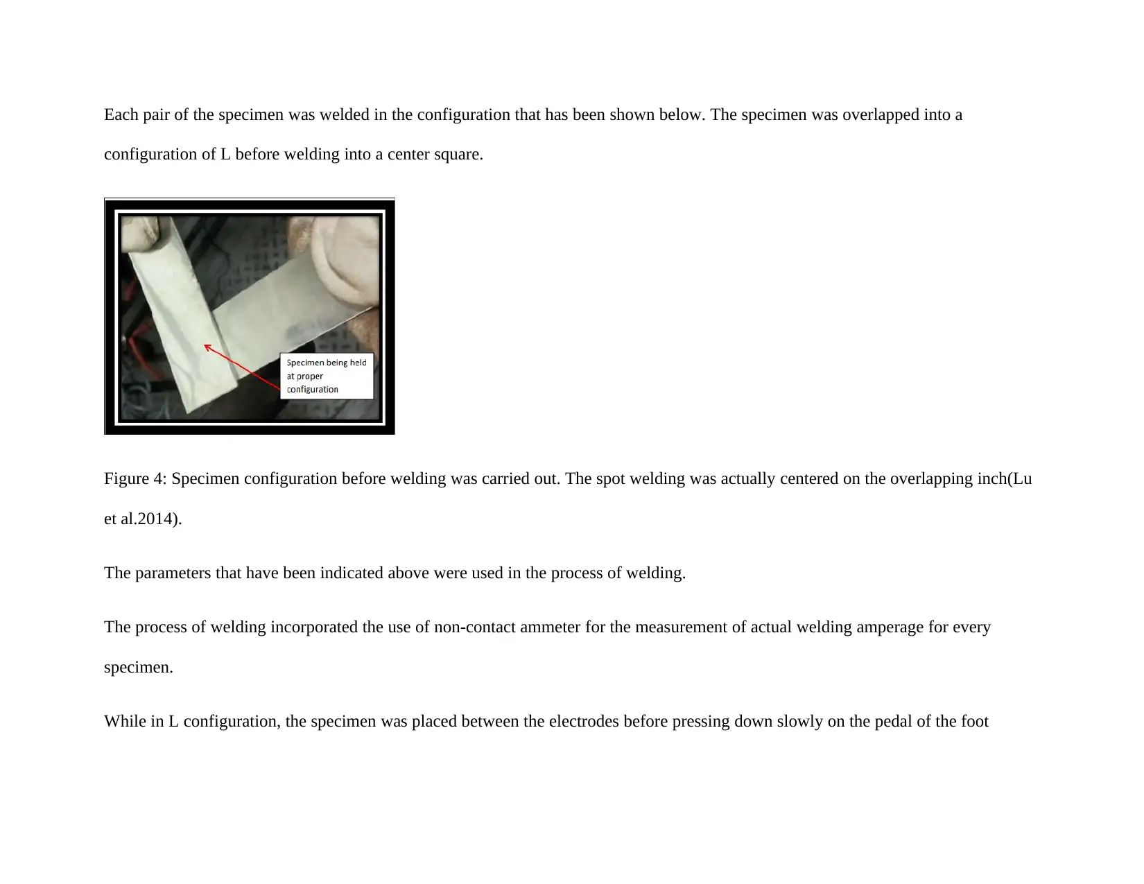
configuration of L before welding into a center square.
Figure 4: Specimen configuration before welding was carried out. The spot welding was actually centered on the overlapping inch(Lu
et al.2014).
The parameters that have been indicated above were used in the process of welding.
The process of welding incorporated the use of non-contact ammeter for the measurement of actual welding amperage for every
specimen.
While in L configuration, the specimen was placed between the electrodes before pressing down slowly on the pedal of the foot
⊘ This is a preview!⊘
Do you want full access?
Subscribe today to unlock all pages.
Trusted by 1+ million students worldwide
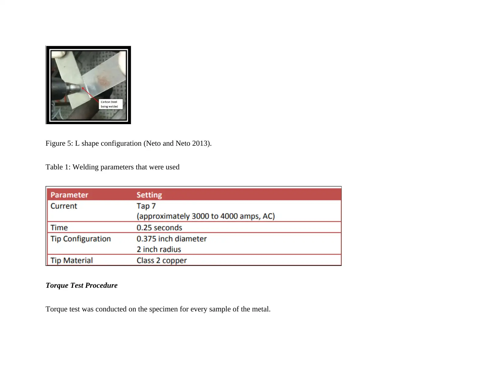
Table 1: Welding parameters that were used
Torque Test Procedure
Torque test was conducted on the specimen for every sample of the metal.
Paraphrase This Document
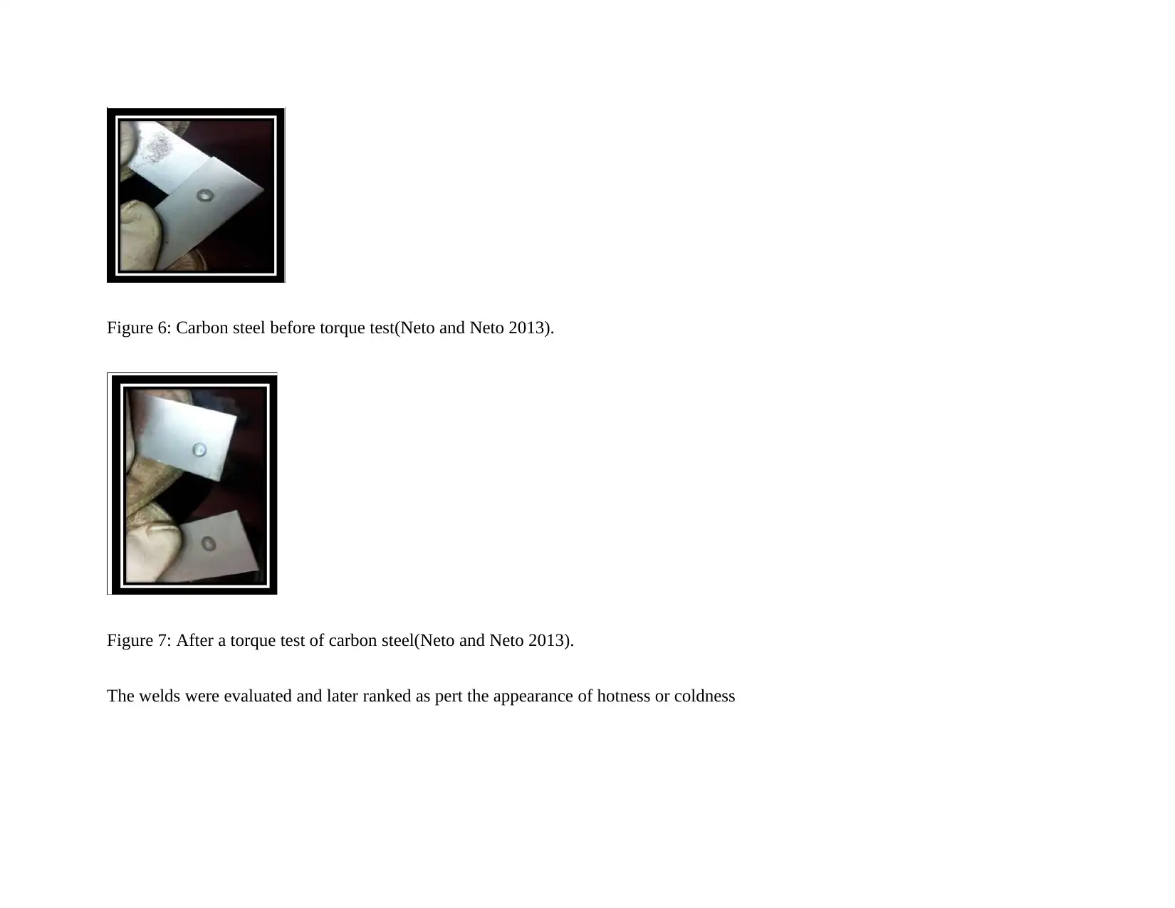
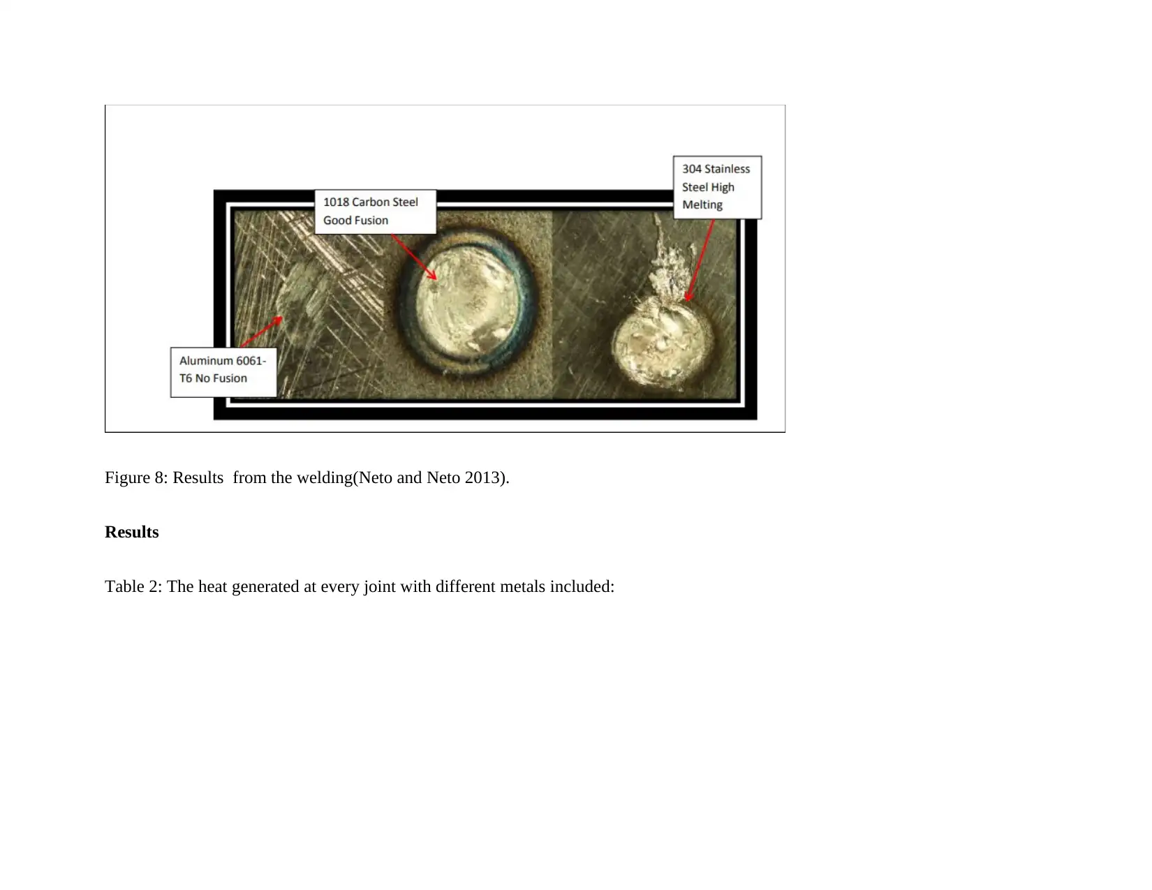
Figure 7: After a torque test of carbon steel(Neto and Neto 2013).
The welds were evaluated and later ranked as pert the appearance of hotness or coldness
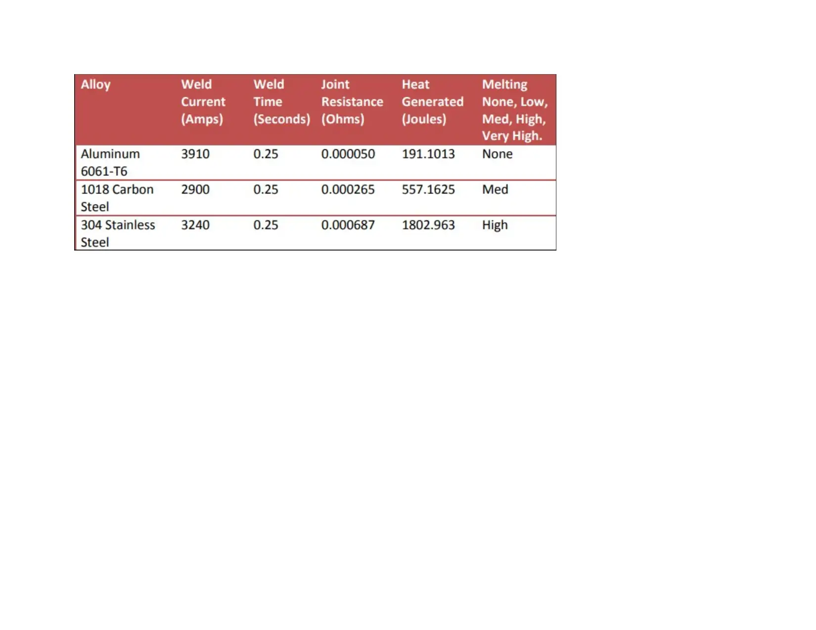
Results
Table 2: The heat generated at every joint with different metals included:
⊘ This is a preview!⊘
Do you want full access?
Subscribe today to unlock all pages.
Trusted by 1+ million students worldwide
Paraphrase This Document
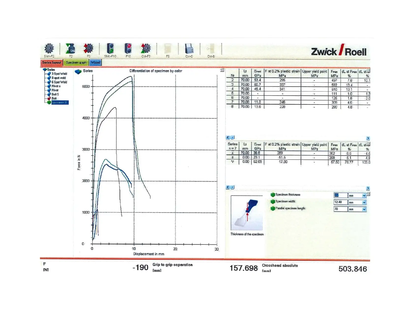
Discussion
Heat Generation
There was a generation of heat in the resistance welds through large quantities of amps that were being poured between two
electrodes. The generated heat was measured in joules.
Importance of surface preparation
It was discovered that the surface preparation of any metal to be welded with resistance welding was very important. This was found
to be perfect with the Aluminium whose surface is always covered with a layer of oxide. In the case of carbon steel, there was a need
to remove oil and dirt. The electrical conductivity was found to be low without removal of dirt and oil or without the surface
preparation. This is because as the electrical current is passed through the layers of oxides and other impurities, it impedes the
resistance that is responsible for the formation of the weld(Panneerselvam and Lenin 2014).
Hot-riveted joint and Bolted joint
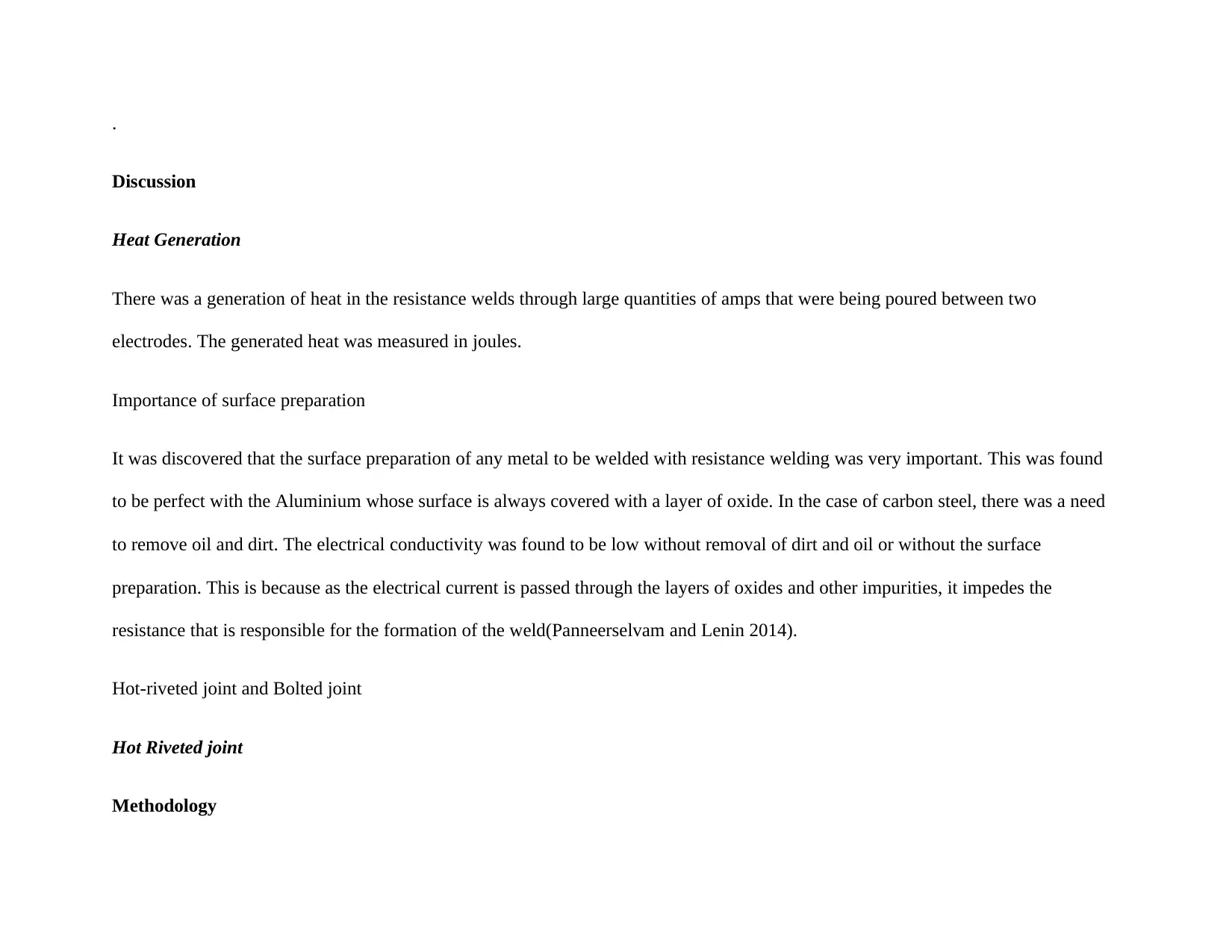
Hot Riveted joint
Methodology
⊘ This is a preview!⊘
Do you want full access?
Subscribe today to unlock all pages.
Trusted by 1+ million students worldwide
A second head was formed tightly against the face of the plates
The temperature was increased to ensure that camping process was readily achieved during the cooling process. This also led to the
creation of the clearance gap.
Figure 9: Hit rivet(Neto and Neto 2013).
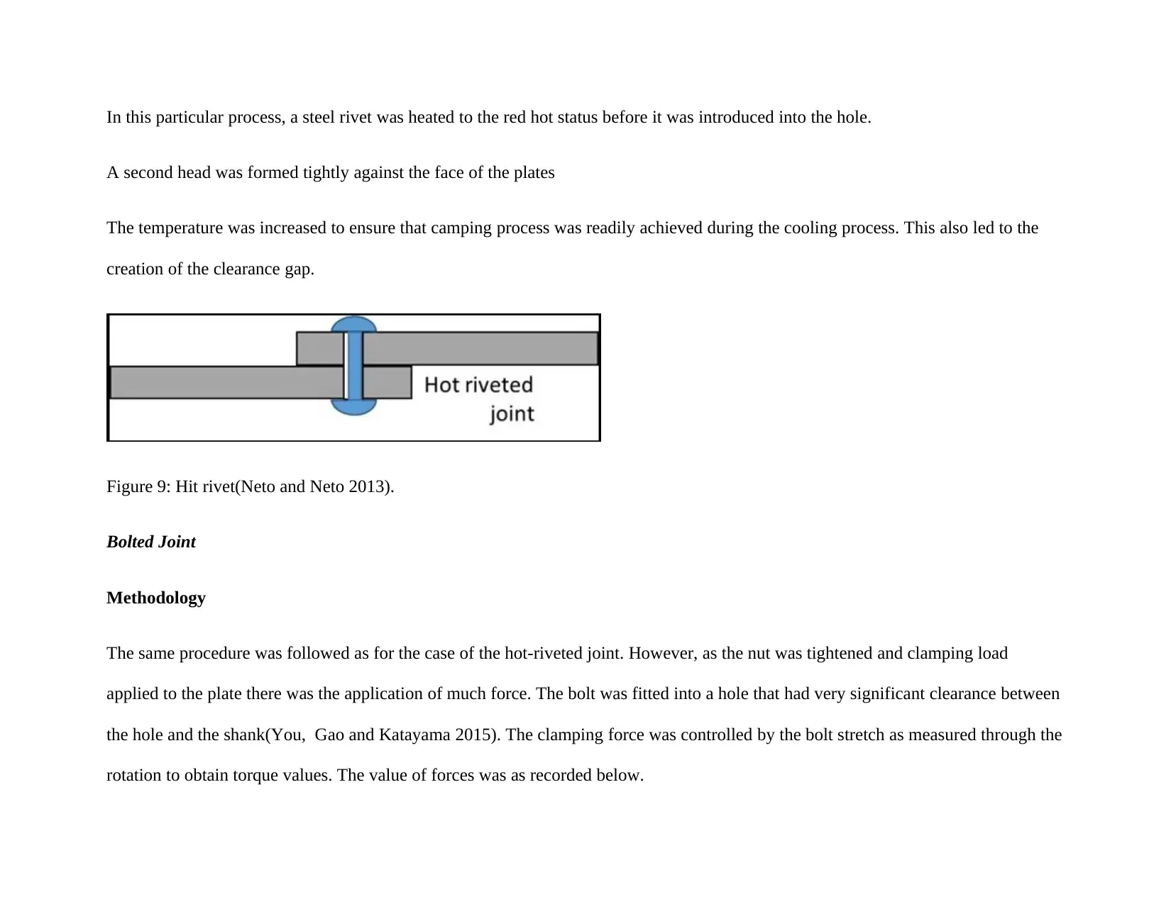
Bolted Joint
Methodology
The same procedure was followed as for the case of the hot-riveted joint. However, as the nut was tightened and clamping load
applied to the plate there was the application of much force. The bolt was fitted into a hole that had very significant clearance between
the hole and the shank(You, Gao and Katayama 2015). The clamping force was controlled by the bolt stretch as measured through the
rotation to obtain torque values. The value of forces was as recorded below.
Paraphrase This Document
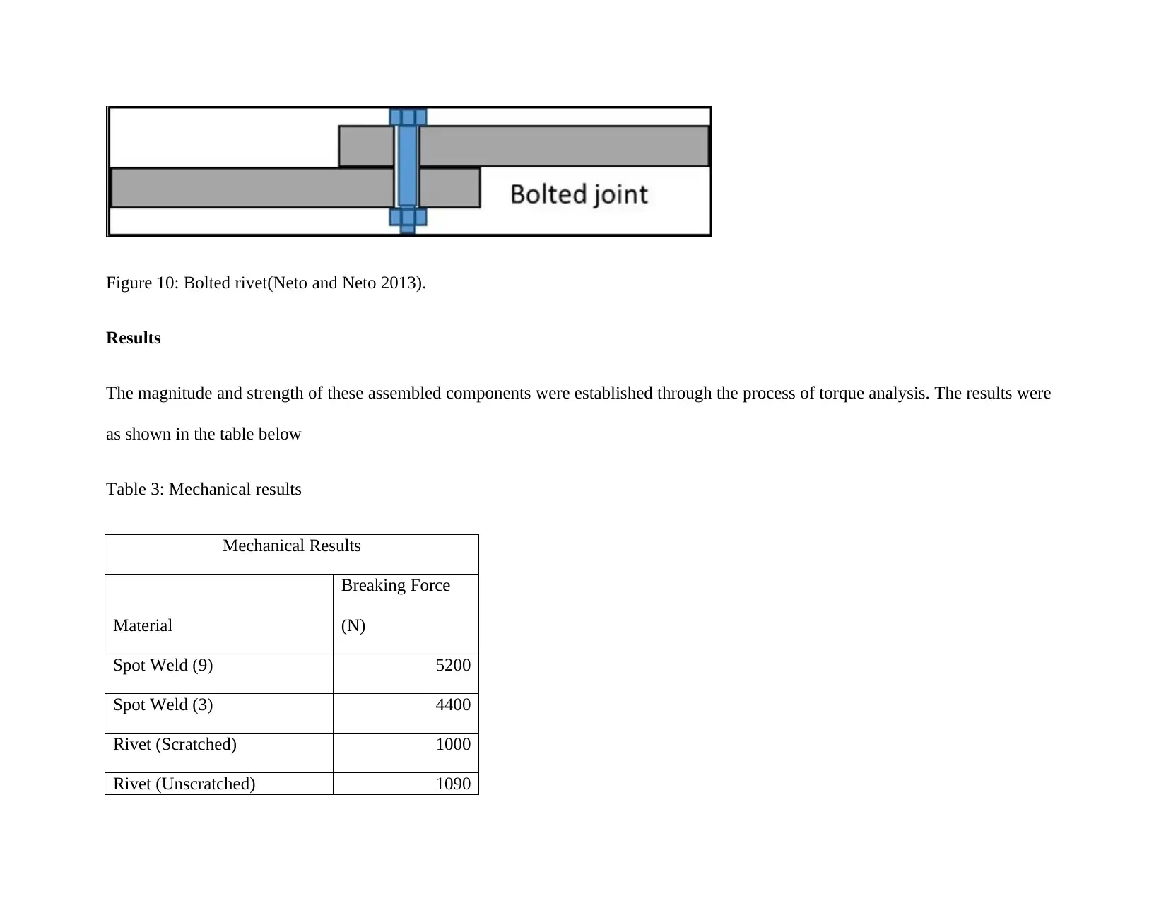
Results
The magnitude and strength of these assembled components were established through the process of torque analysis. The results were
as shown in the table below
Table 3: Mechanical results
Mechanical Results
Material
Breaking Force
(N)
Spot Weld (9) 5200
Spot Weld (3) 4400
Rivet (Scratched) 1000
Rivet (Unscratched) 1090

Bolt (Unscratched) 2550
⊘ This is a preview!⊘
Do you want full access?
Subscribe today to unlock all pages.
Trusted by 1+ million students worldwide

Paraphrase This Document
Adhesives
Methodology
Cure rates of an adhesive are normally treated as a critical process in the determination of the process of manufacture. The physical
behavior of curing adhesive during the processing can also have an impact on the general route of manufacture. This implies that there
has been a considerable amount of work that is undertaken in the development of the techniques in the monitoring and measuring the
state of cure of the commonly known adhesives(Gibson et al.2014). The project has investigated laboratory methods in the monitoring
and quantifying cure of adhesives The comparison of the forces for scratched and unscratched were made.
Materials
Scratch and Unscratched Gorilla glue
Scratched and Unscratched Grab Adhesive.
Araldite both scratched and unscratched
Scratch and Unscratched Super glues
Scratch and Unscratched Tape
bonding and strengthening of the members of the car bonnet alongside welds.
This adhesive technique has found its use to increase the load carrying capacity of the structural members thereby reducing deflection.
The application of structural strengthening includes the following:
Minimizing the effect of deflections
Increasing load carrying capacity
Restoring strengths to the repaired structures that might have suffered damage.
Measurement techniques
The above adhesives were subjected to proper evaluation by the use of the three important techniques:
I. Mechanical testing which involved tensile testing of the cured specimen of adhesives, measurement of shear storage modulus
through rheological testing and finally lap shear joint testing.
II. Differential calorimetry scanning which was used in the measurement of the heat evolved during the process of the chemical
curing
III. Finally, non –destructive testing included the application of the ultrasound and high frequency of dielectric testing.
Resultant Forces from the testing
⊘ This is a preview!⊘
Do you want full access?
Subscribe today to unlock all pages.
Trusted by 1+ million students worldwide
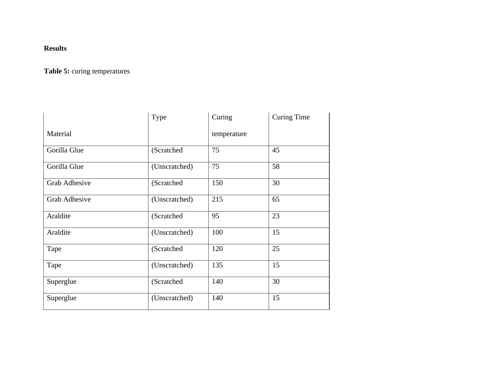
Table 5: curing temperatures
Material
Type Curing
temperature
Curing Time
Gorilla Glue (Scratched 75 45
Gorilla Glue (Unscratched) 75 58
Grab Adhesive (Scratched 150 30
Grab Adhesive (Unscratched) 215 65
Araldite (Scratched 95 23
Araldite (Unscratched) 100 15
Tape (Scratched 120 25
Tape (Unscratched) 135 15
Superglue (Scratched 140 30
Superglue (Unscratched) 140 15
Paraphrase This Document
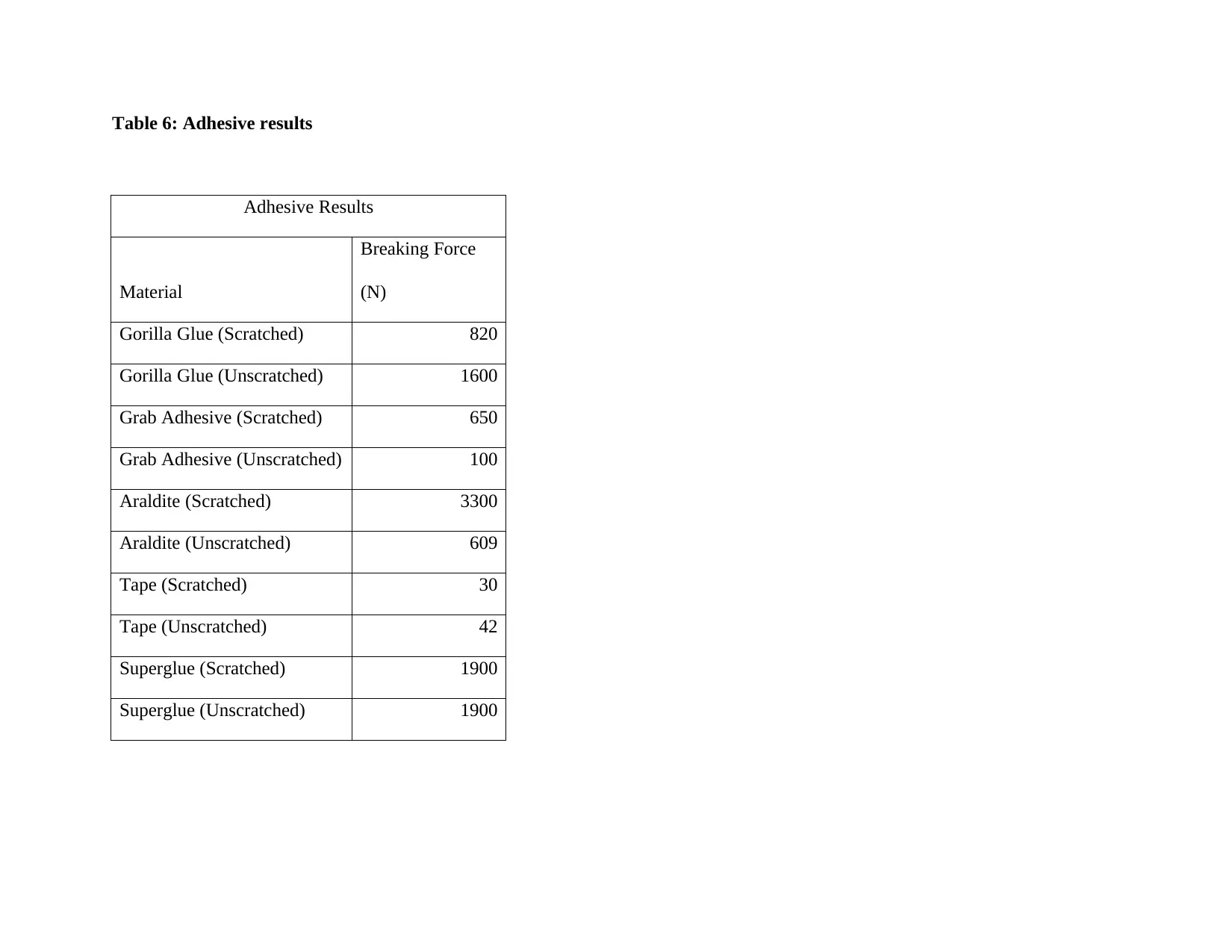
Adhesive Results
Material
Breaking Force
(N)
Gorilla Glue (Scratched) 820
Gorilla Glue (Unscratched) 1600
Grab Adhesive (Scratched) 650
Grab Adhesive (Unscratched) 100
Araldite (Scratched) 3300
Araldite (Unscratched) 609
Tape (Scratched) 30
Tape (Unscratched) 42
Superglue (Scratched) 1900
Superglue (Unscratched) 1900
⊘ This is a preview!⊘
Do you want full access?
Subscribe today to unlock all pages.
Trusted by 1+ million students worldwide
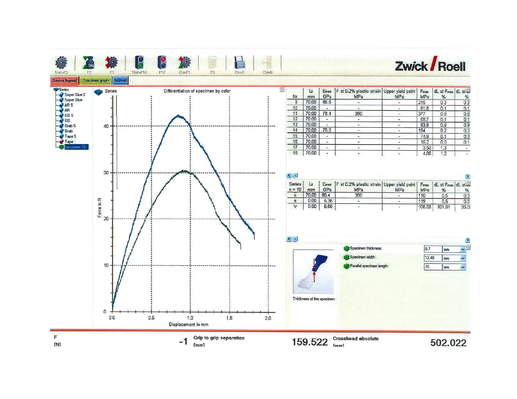
Discussions
The typical data that was obtained from the adhesives that were under investigation have been summarized in the table above. The
data were at a range of temperature. There was a comparison of the mechanical test with the mechanical characteristics of the samples
that were treated irrespective of the adhesive material used. This involved the calculations of the shear modulus which actually
provided the tabulated results in terms of the forces as summarized in the table above. During the investigation process, it was
discovered that a large proportion of the strain occurs at the points of intact or at the joints. Further analysis indicated that for stiff
materials the torque used in the geometry tightening was directly proportional as from the rheological testing results.
Conclusion
The application of engineering materials has been very diverse in late. Studies and research work are continuously revealing the best
ways of improving their properties. The modification process includes welding, use of adhesives, riveting among others to accomplish
the specific requirements or demands of an engineering task. During the laboratory work, the effectiveness of the engineering process
like spot welding and riveting were evaluated. The processes involved the use of the standards tools and processes so as to produce
reliable resources. The quality of the joints was evaluated by different engineering test including ultrasound technique. This was done
after the proper research had been conducted in regard to the application of different joints.
Paraphrase This Document
Gadakh, V.S., Shinde, V.B., and Khemnar, N.S., 2013. Optimization of welding process parameters using MOORA method. The
International Journal of Advanced Manufacturing Technology, 69(9-12), pp.2031-2039.
Gibson, B.T., Lammlein, D.H., Prater, T.J., Longhurst, W.R., Cox, C.D., Ball, M.C., Dharmaraj, K.J., Cook, G.E. and Strauss, A.M.,
2014. Friction stir welding: Process, automation, and control. Journal of Manufacturing Processes, 16(1), pp.56-73.
Kanemaru, S., Sasaki, T., Sato, T., Mishima, H., Tashiro, S. and Tanaka, M., 2014. Study for TIG–MIG hybrid welding
process. Welding in the World, 58(1), pp.11-18.
Kreindl, J. and Glanseck, S., Fronius International GmbH, 2014. Device and method for simulating a welding process. U.S. Patent
8,777,629.
Lee, S.J., Kim, Y.H., Kim, J.K., Baik, H., Park, J.H., Lee, J., Nam, J., Park, J.H., Lee, T.W., Yi, G.R. and Cho, J.H., 2014. A roll-to-
roll welding process for planarized silver nanowire electrodes. Nanoscale, 6(20), pp.11828-11834.
Lu, Y., Chen, S., Shi, Y., Li, X., Chen, J., Kvidahl, L. and Zhang, Y.M., 2014. Double-electrode arc welding process: principle,
variants, control, and developments. Journal of Manufacturing Processes, 16(1), pp.93-108.
Advanced Manufacturing Technology, 65(1-4), pp.115-126.
Panneerselvam, K. and Lenin, K., 2014. Joining of Nylon 6 plate by friction stir welding process using a threaded pin profile.
Materials & Design, 53, pp.302-307.
Wu, C.S., Wang, L., Ren, W.J. and Zhang, X.Y., 2014. Plasma arc welding: Process, sensing, control, and modeling. Journal of
manufacturing processes, 16(1), pp.74-85.
You, D., Gao, X. and Katayama, S., 2015. WPD-PCA-based laser welding process monitoring and defects diagnosis by using FNN
and SVM. IEEE Transactions on Industrial Electronics, 62(1), pp.628-636.
⊘ This is a preview!⊘
Do you want full access?
Subscribe today to unlock all pages.
Trusted by 1+ million students worldwide
Related Documents


Your All-in-One AI-Powered Toolkit for Academic Success.
+13062052269
info@desklib.com
Available 24*7 on WhatsApp / Email
![[object Object]](/_next/static/media/star-bottom.7253800d.svg)
© 2024 | Zucol Services PVT LTD | All rights reserved.