ME3407 Heat Transfer Coursework: Assignment Solution 2019/2020
VerifiedAdded on 2022/09/12
|17
|734
|47
Homework Assignment
AI Summary
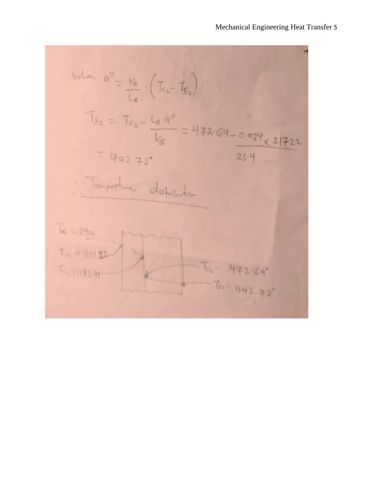
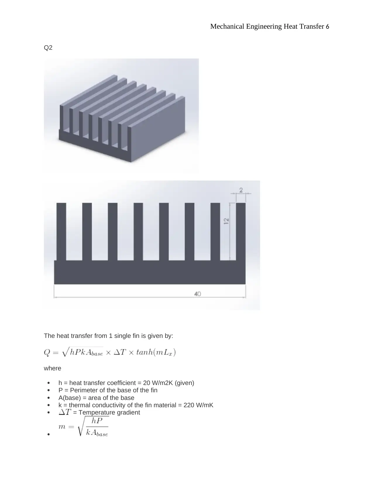
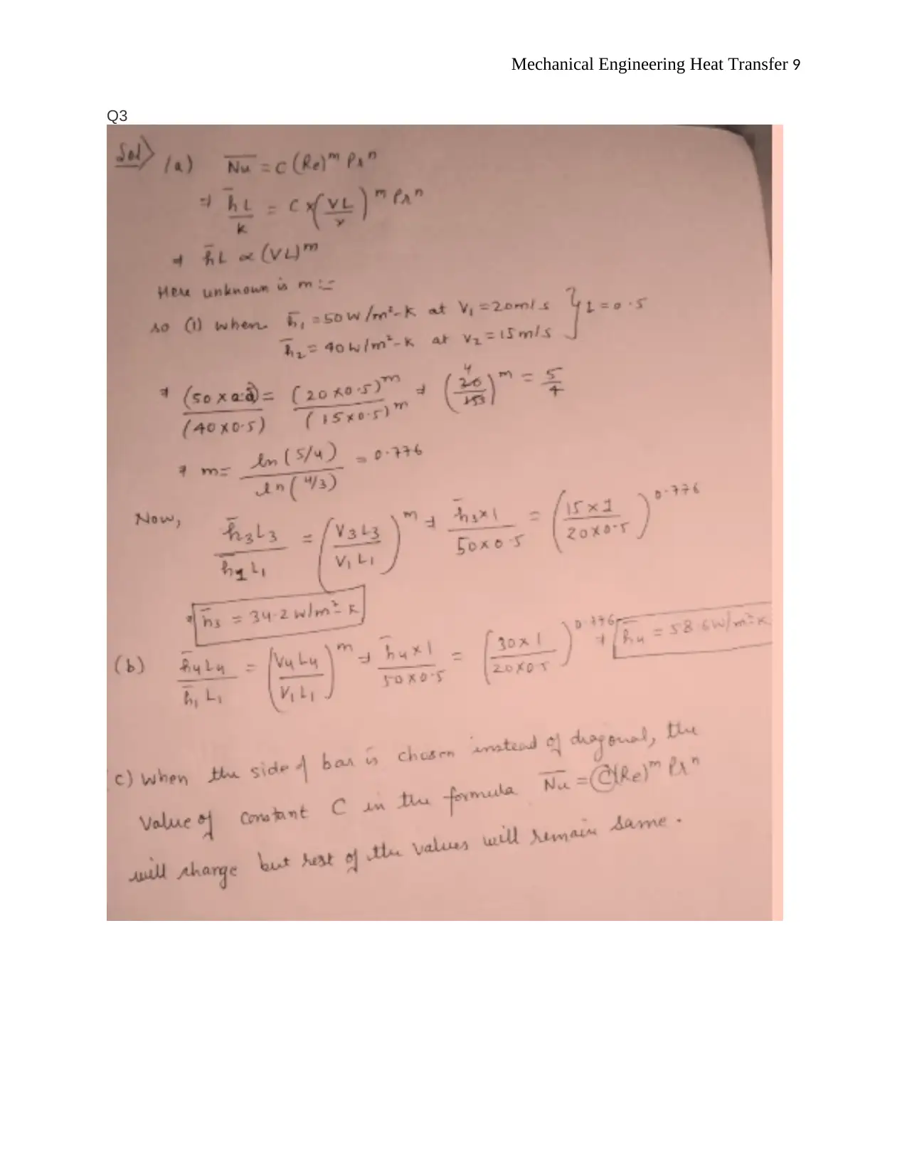
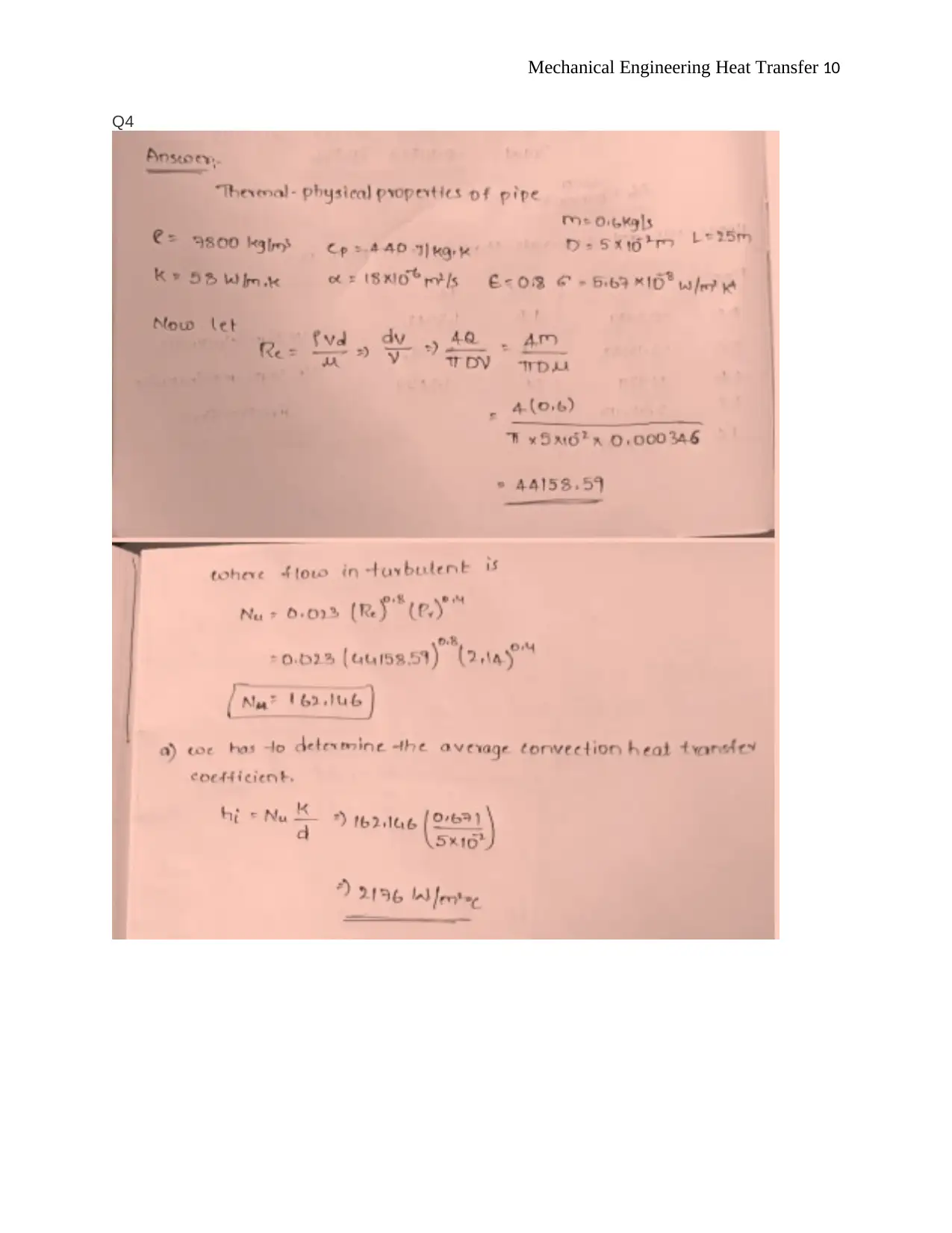
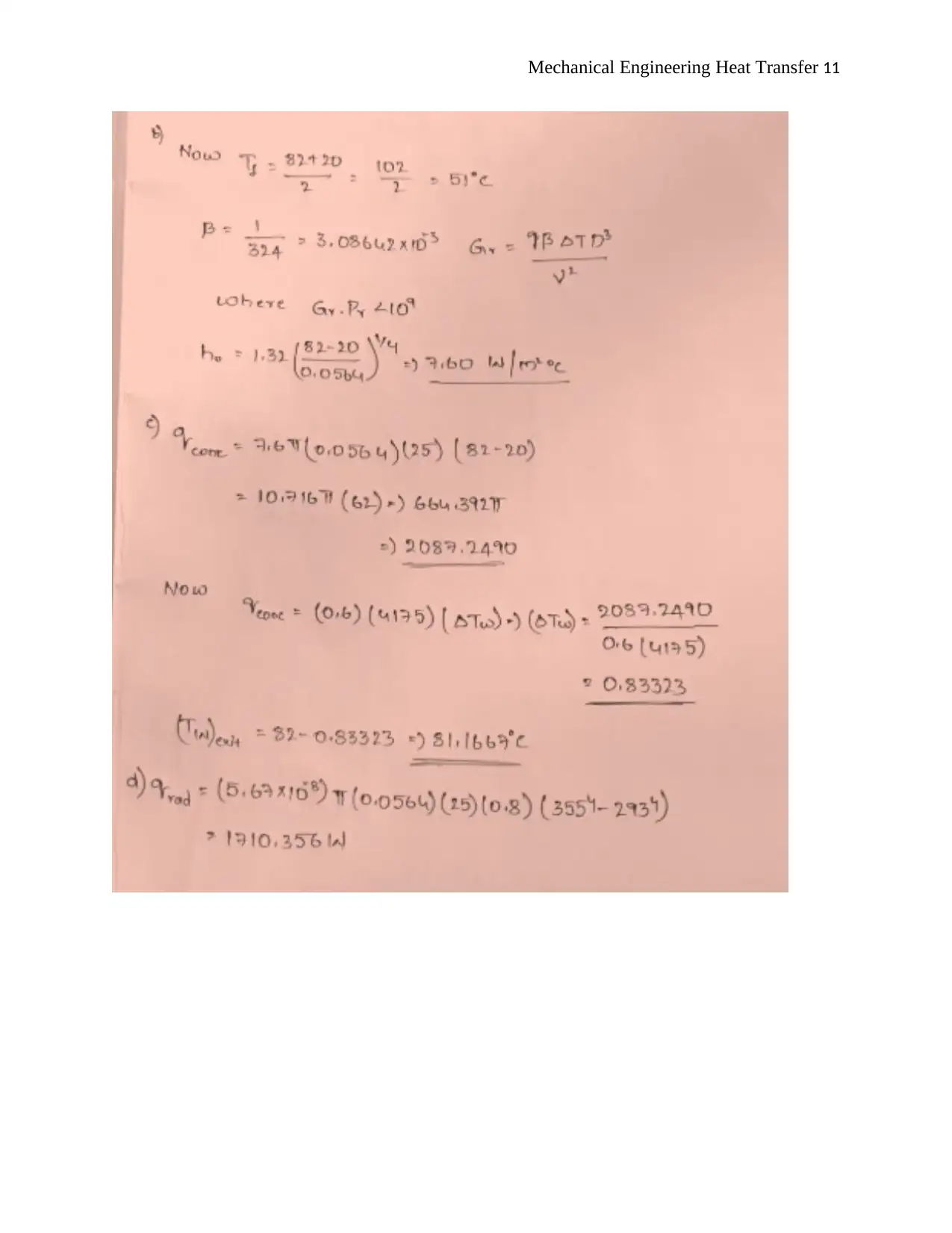
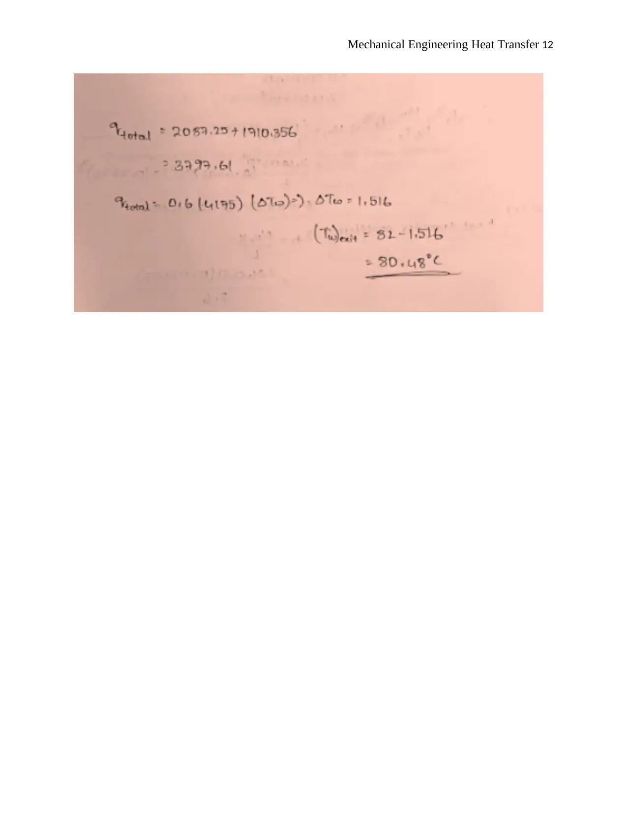
This document presents a detailed solution to a mechanical engineering heat transfer assignment. The assignment covers the analysis of heat transfer in a composite wall, including calculations for thermal resistances, heat loss, and temperature distribution. It also involves the analysis of heat transfer from a CPU with attached rectangular fins, calculating heat transfer rates from fins and bare surfaces, and determining overall surface efficiency. The solution includes step-by-step calculations, formulas, and considerations for convection and conduction heat transfer. Furthermore, the assignment explores the application of these principles to practical engineering problems, providing a comprehensive understanding of heat transfer concepts and their application in real-world scenarios. The assignment is well-structured and provides a thorough understanding of the subject matter.
1 out of 17


Your All-in-One AI-Powered Toolkit for Academic Success.
+13062052269
info@desklib.com
Available 24*7 on WhatsApp / Email
![[object Object]](/_next/static/media/star-bottom.7253800d.svg)
Copyright © 2020–2026 A2Z Services. All Rights Reserved. Developed and managed by ZUCOL.