AERO5815C Assignment: Analysis of Mechanical Flight Control System
VerifiedAdded on 2023/06/07
|5
|1203
|195
Report
AI Summary
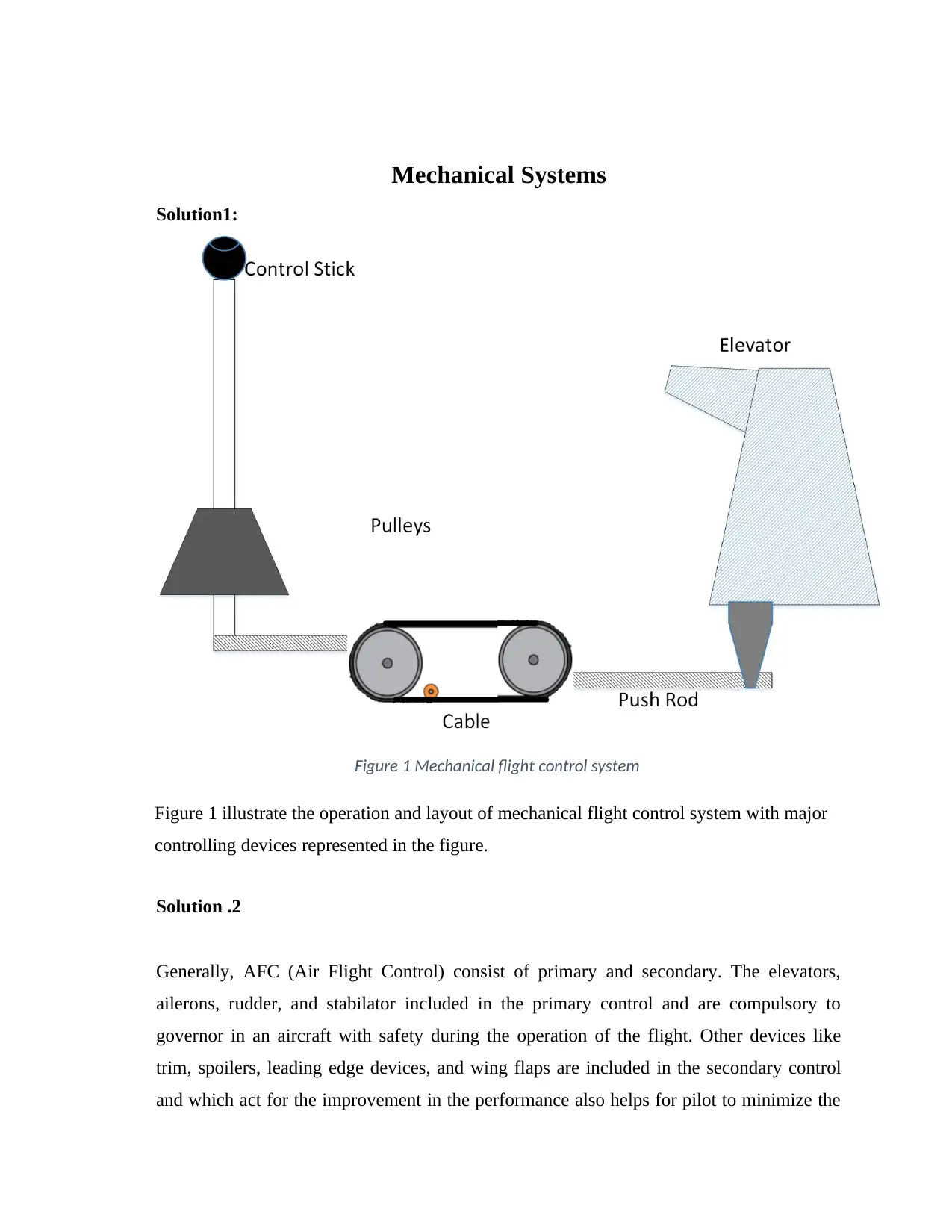
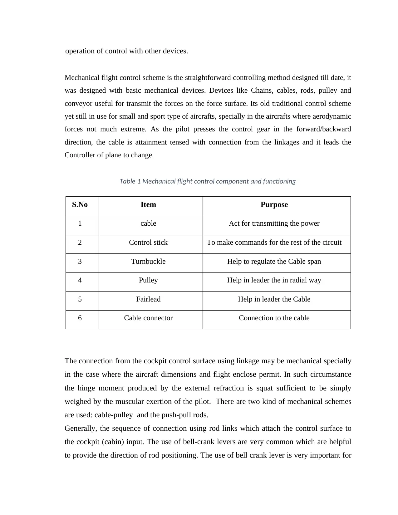
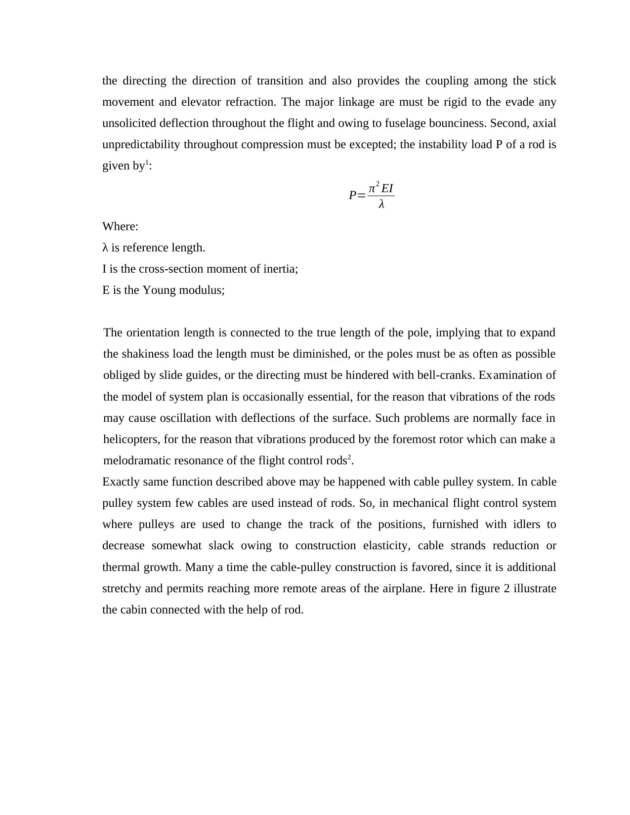
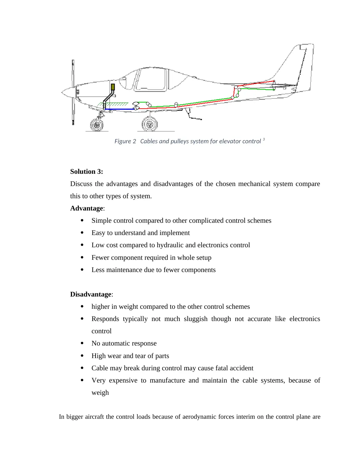
This report provides a detailed analysis of mechanical flight control systems, focusing on their operation, components, advantages, and disadvantages. It begins by illustrating the layout of a typical mechanical flight control system, highlighting key controlling devices. The report then delves into the primary and secondary controls within an Air Flight Control (AFC) system, emphasizing the importance of elevators, ailerons, and rudders for safe aircraft operation. It discusses the straightforward nature of mechanical flight control schemes, which rely on chains, cables, rods, and pulleys to transmit forces. The document further examines the maintenance requirements of these systems, including lubrication and rigging, and references relevant literature to support its findings. The report concludes by comparing mechanical systems to other types of flight control systems, weighing their benefits against drawbacks like weight and responsiveness.

Mechanical Systems
Solution1:
Figure 1 Mechanical flight control system
Figure 1 illustrate the operation and layout of mechanical flight control system with major
controlling devices represented in the figure.
Solution .2
Generally, AFC (Air Flight Control) consist of primary and secondary. The elevators,
ailerons, rudder, and stabilator included in the primary control and are compulsory to
governor in an aircraft with safety during the operation of the flight. Other devices like
trim, spoilers, leading edge devices, and wing flaps are included in the secondary control
and which act for the improvement in the performance also helps for pilot to minimize the
Paraphrase This Document
Need a fresh take? Get an instant paraphrase of this document with our AI Paraphraser

operation of control with other devices.
Mechanical flight control scheme is the straightforward controlling method designed till date, it
was designed with basic mechanical devices. Devices like Chains, cables, rods, pulley and
conveyor useful for transmit the forces on the force surface. Its old traditional control scheme
yet still in use for small and sport type of aircrafts, specially in the aircrafts where aerodynamic
forces not much extreme. As the pilot presses the control gear in the forward/backward
direction, the cable is attainment tensed with connection from the linkages and it leads the
Controller of plane to change.
Table 1 Mechanical flight control component and functioning
S.No Item Purpose
1 cable Act for transmitting the power
2 Control stick To make commands for the rest of the circuit
3 Turnbuckle Help to regulate the Cable span
4 Pulley Help in leader the in radial way
5 Fairlead Help in leader the Cable
6 Cable connector Connection to the cable
The connection from the cockpit control surface using linkage may be mechanical specially
in the case where the aircraft dimensions and flight enclose permit. In such circumstance
the hinge moment produced by the external refraction is squat sufficient to be simply
weighed by the muscular exertion of the pilot. There are two kind of mechanical schemes
are used: cable-pulley and the push-pull rods.
Generally, the sequence of connection using rod links which attach the control surface to
the cockpit (cabin) input. The use of bell-crank levers are very common which are helpful
to provide the direction of rod positioning. The use of bell crank lever is very important for

the directing the direction of transition and also provides the coupling among the stick
movement and elevator refraction. The major linkage are must be rigid to the evade any
unsolicited deflection throughout the flight and owing to fuselage bounciness. Second, axial
unpredictability throughout compression must be excepted; the instability load P of a rod is
given by1:
P= π2 EI
λ
Where:
λ is reference length.
I is the cross-section moment of inertia;
E is the Young modulus;
The orientation length is connected to the true length of the pole, implying that to expand
the shakiness load the length must be diminished, or the poles must be as often as possible
obliged by slide guides, or the directing must be hindered with bell-cranks. Examination of
the model of system plan is occasionally essential, for the reason that vibrations of the rods
may cause oscillation with deflections of the surface. Such problems are normally face in
helicopters, for the reason that vibrations produced by the foremost rotor which can make a
melodramatic resonance of the flight control rods2.
Exactly same function described above may be happened with cable pulley system. In cable
pulley system few cables are used instead of rods. So, in mechanical flight control system
where pulleys are used to change the track of the positions, furnished with idlers to
decrease somewhat slack owing to construction elasticity, cable strands reduction or
thermal growth. Many a time the cable-pulley construction is favored, since it is additional
stretchy and permits reaching more remote areas of the airplane. Here in figure 2 illustrate
the cabin connected with the help of rod.
You're viewing a preview
Unlock full access by subscribing today!

Figure 2 Cables and pulleys system for elevator control 3
Solution 3:
Discuss the advantages and disadvantages of the chosen mechanical system compare
this to other types of system.
Advantage:
Simple control compared to other complicated control schemes
Easy to understand and implement
Low cost compared to hydraulic and electronics control
Fewer component required in whole setup
Less maintenance due to fewer components
Disadvantage:
higher in weight compared to the other control schemes
Responds typically not much sluggish though not accurate like electronics
control
No automatic response
High wear and tear of parts
Cable may break during control may cause fatal accident
Very expensive to manufacture and maintain the cable systems, because of
weigh
In bigger aircraft the control loads because of aerodynamic forces interim on the control plane are
Paraphrase This Document
Need a fresh take? Get an instant paraphrase of this document with our AI Paraphraser

very high in simple mechanical controls. That’s why two mechanical solution are proposed. One in
which attempt is made to extract the high mechanical strength through pulleys and levers but
maximum reduction in force is restricted by mechanical components
Solution :
Mostly the maintenance of the mechanical flight control system is arising in the cockpit control to
the control surfaces which may comprise but is not restricted to the ailerons, flaps, leading edge
devices, elevators, fixed point and adjustable trimming devices cables, push-pull rods, Pulleys,
fairleads, and bell cranks. Generally, manufacturer publish the maintenance requirement of
mechanical flight control system because FAA made mandatory annual inspection and maintenance
requirement which is important for the health of aircraft generally ranges from quarterly, or yearly.
Very important part of maintenance in mechanical flight control system is the proper lubrication of
parts according to schedule and after inspection. Improper lubrication may cause high wear and tear
on mechanical devices. Rigging of mechanical flight control system may include proper positioning
of control surface and the tension adjustment in the cable connection, springs and the linkages.
Many a times rigging is the neglected during maintenance task because its very difficult process in
many aircrafts. Calibrated tension meter is required for the adjustment of the tension in cable. High
tension in cable may cause break down and lose may lead to delay in response. Control lever must
be check against the free movement, linkages must be properly lubricated, rigging must be done
and pulley shaft must be checked during the maintenance process.
References:
1. Moir, Ian and Allan Seabridge, Aircraft systems: mechanical, electrical, and avionics subsystems
integration (John Wiley & Sons, 2011) vol 52
2. Thomas B and William R Ferrell, 'Remote manipulative control with transmission delay' (1963)
(1) IEEE Transactions on Human Factors in Electronics 25
3. Flight Control System by Pritam Ashutosh
Available online [https://pritamashutosh.wordpress.com/2012/11/17/flight-control-system/]
1 out of 5

Your All-in-One AI-Powered Toolkit for Academic Success.
+13062052269
info@desklib.com
Available 24*7 on WhatsApp / Email
Unlock your academic potential
© 2024 | Zucol Services PVT LTD | All rights reserved.