Analysis of Mechanical Systems: Gears, Clutches, and Kinetics
VerifiedAdded on 2020/04/01
|11
|1356
|70
AI Summary
The problem set provided requires analysis and calculations related to various mechanical components including gears, clutches, and flywheels. Tasks involve determining the output speeds and moments of inertia for different configurations and examining kinetic energy changes during operati...
MecHAnical Principle
Numerical Problems
Numerical Problems
Paraphrase This Document
Need a fresh take? Get an instant paraphrase of this document with our AI Paraphraser
Contents
Solution Task 1......................................................................................................................................2
Solution Task 2......................................................................................................................................3
Option 1.............................................................................................................................................3
Option 2: Epicyclic Gear Train............................................................................................................4
Solution Task 3......................................................................................................................................5
Solution Task 4......................................................................................................................................6
Task 4a...............................................................................................................................................6
Task 4b...............................................................................................................................................6
Task 4c...............................................................................................................................................7
Solution Task 5......................................................................................................................................7
Solution Task 6......................................................................................................................................9
Variable A Variable B Variable C Variable D Variable E (Kg m2)
(RPM) (Nm) (RPM) (RPM)
Jack Williamson 1350 49 980 1055 1.27
Solution Task 1
Given Data:
Speed, N in rpm – 1350
T 1 +T 2 = 220 N
Diameter of the Input wheel, d = 240 mm = 0.24 m
Now, we know that Velocity of the belt, v = πdN
60 = 3.14∗0.24∗1350
60 = 1017.36
60 = 16.95 m/s
Lap Angle, θ = 165⁰= (165/180) * π = 2.88 rad/s
We know that, Tension in belts:
T1
T2
= eμθ
Consider, μ = 0.3
T1
T2
= e0.3∗2.88 = 2.372
Or, T 1 = 2.372 T 2
Substituting it in T 1 +T 2 = 220 N, we have
2.372 T 2+T 2 = 220 N
3.372 T 2 = 220 N
Or, T 2 = 220/3.372 = 65.243 N
And, T 1 = 220 – 65.243 N
T 1 = 154.76 N
Power transmitted, P = (T 1 -T 2) v = (154.76 -65.24) * 16.95 = 89.52 * 16.95 = 1517.3 W = 1.51 KW
For V Belt Drive, we know that
T1
T2
= eμθ Cosec β
Here, Sheave angle, 2β = 40
Or, β = 20°
⊘ This is a preview!⊘
Do you want full access?
Subscribe today to unlock all pages.
Trusted by 1+ million students worldwide
T1
T2
= eμθ Cosec β
T1
T2
= e0.3∗2.88∗cosec20 = e0.3∗2.88∗2.93 = e2.52 = 12.50
Or, T 1 = 12.50 T 2
Substituting it in T 1 +T 2 = 220 N, we have
12.50 T 2+T 2 = 220 N
13.50 T 2 = 220 N
Or, T 2 = 220/13.50 = 16.29 N
And, T 1 = 220 – 16.29 N
T 1 = 203.71 N
Power transmitted, P = (T 1 -T 2) v = (203.71 -16.29) * 16.95 = 187.42 * 16.95 = 3176.7 W = 3.17 KW
It is clear from the above calculation, that power transmitted via the V Belt Drive
is more than the Flat Belt Drive with same configuration.
Solution Task 2
Option 1
b. Gear Ratio GR = N A
N D
= Product of Driven Tooth
Product of Driving Tooth = T B∗T D
T A∗T C
= 150∗60
50∗30 = 9000
1500 = 6
Also, N A = 6 N D
τ A = 49 Nm
ŋ=¿0.7
Input Power = 3176.7 W
Output Power = Input Power * ŋ
c. Output Power = 3176.7 * 0.7 = 2223.7 W
Input Power, PA = 2 π N A τ A
60
Or, 3176.7 = 2∗3.14∗49∗N A
60
Or, N A = 3176.7∗60
2∗3.14∗49 = 190602
307.72 = 619.4 rpm
Hence, N D = 619.4/6 = 103.2 rpm (Output Speed)
T2
= eμθ Cosec β
T1
T2
= e0.3∗2.88∗cosec20 = e0.3∗2.88∗2.93 = e2.52 = 12.50
Or, T 1 = 12.50 T 2
Substituting it in T 1 +T 2 = 220 N, we have
12.50 T 2+T 2 = 220 N
13.50 T 2 = 220 N
Or, T 2 = 220/13.50 = 16.29 N
And, T 1 = 220 – 16.29 N
T 1 = 203.71 N
Power transmitted, P = (T 1 -T 2) v = (203.71 -16.29) * 16.95 = 187.42 * 16.95 = 3176.7 W = 3.17 KW
It is clear from the above calculation, that power transmitted via the V Belt Drive
is more than the Flat Belt Drive with same configuration.
Solution Task 2
Option 1
b. Gear Ratio GR = N A
N D
= Product of Driven Tooth
Product of Driving Tooth = T B∗T D
T A∗T C
= 150∗60
50∗30 = 9000
1500 = 6
Also, N A = 6 N D
τ A = 49 Nm
ŋ=¿0.7
Input Power = 3176.7 W
Output Power = Input Power * ŋ
c. Output Power = 3176.7 * 0.7 = 2223.7 W
Input Power, PA = 2 π N A τ A
60
Or, 3176.7 = 2∗3.14∗49∗N A
60
Or, N A = 3176.7∗60
2∗3.14∗49 = 190602
307.72 = 619.4 rpm
Hence, N D = 619.4/6 = 103.2 rpm (Output Speed)
Paraphrase This Document
Need a fresh take? Get an instant paraphrase of this document with our AI Paraphraser
If A is anticlockwise means, B and C is clockwise and D is anticlockwise.
d. Holding Torque
Now, τ D = P (output )∗60
2∗3.14∗N D
= 2223.7∗60
2∗3.14∗103.2 = 133422
648.096 = 205.86 Nm
Also, we know that,
τ A +τ D + τhold = 0
τ hold = - (205.86 + 49) = -254.86 Nm
Option 2: Epicyclic Gear Train
T B = 50
T C = 180
T D = 80
τ A = 49 Nm
ŋ=¿0.7
Gear Box Ratio = 1+ T D
T C
= 1+ 80
180 = 1.44
Since, the arm make anticlockwise torque of 49 Nm
y = 49
Also, x+ y = 49
Hence, x = -49
Speed of wheel C = Output Speed = y-x T c
T D
= 49 – 49 * 180
80 = 61.25 rpm
(Anticlockwise)
Output Power = Input Power = 3176.7 W
Output Power = Input Power * ŋ
Output Power = 3176.7 * 0.6 = 1906.2 W
Also, Ouput Power, PC = 2 π NC τC
60
Or, 1906.2 = 2∗3.14∗61.25∗τC
60
τC = 1906.2∗60
2∗3.14∗61.25 = 114372
384.65 = 297.3 Nm
Also, we know that,
Also, we know that,
τ A +τC +τhold = 0
τ hold = - (297.3 + 61.25) = -358.5 Nm
Solution Task 3
As we know that efficiency of cone clutch is much higher when compared
with the plate clutch, we will be using the cone clutch for the transmission
of power.
Power to be transmitted via cone clutch = 2223.7 W = 2.23 kW
At speed = 103.2 rpm
Considering the semi cone angle to be 20 degrees and the co-efficient of
friction at 0.2, lets us calculate the dimension of conical bearing surface
Let r 1 and r 2 be the external and internal radii of the bearing surface respectively
b = Width of the bearing surface in mm,
T = Torque transmitted.
We know that,
Power transmitted (P) = T*ω = 2 π NT
60 = 2∗3.14∗103.2∗T
60
T = 2223.7∗60
2∗3.14∗103.2 = 133422
648.1 = 205.86 * 103 Nmm
We also know that the torque transmitted,
T = 2 πμ R2 pn b
205.86 * 103=¿2*3.14* 0.2*187.5*187.5* 0.25*b
Considering the normal pressure as 0.25 N /mm2 and the mean diameter as 375
mm
b = 205.86 * 103/11039 = 18.64 mm
We also know that,
r1 +r2 = 375
r1−r2 = bsinα = 18.64 * sin 20 = 6.375
Solving both equation,
6.375+r2 +r 2 = 375
2r2 = 375-6.375 = 368.625
⊘ This is a preview!⊘
Do you want full access?
Subscribe today to unlock all pages.
Trusted by 1+ million students worldwide
Or, r2 = 368.62/2 = 184.31 mm
And, r1 = 375 – 184.31 = 190.69 mm
Axial Load required can also be calculated as,
W = 2* π* pn*r2 (r1 - r2)
W = 2*3.14*0.25*184.31 (190.69 -184.31) = 2067.7 N
Solution Task 4
Task 4a
Power developed, P = 2223.7 W
N1 = 1055 rpm
N2 = 980 rpm
Mean Speed, N = (1055+980)/2 = 1017.5 rpm
k = 0.3 m
Now, Fluctuation of Speed, Cs = N 1−N2
N = 1055−980
1017.5 = 0.073
Work done per cycle, W = P∗60
N = 2223.7∗60
1017.5 = 131.12 Nm
Maximum fluctuation of Energy = 150-90 = 60 Nm
We also know that,
Maximum fluctuation of Energy, ∆E = m*k 2 ¿ ω2∗Cs
Or, m = ∆E/ (k 2 ¿ ω2∗Cs ¿
And, ω = 2 π N
60 = 2∗3.14∗1017.5
60 = 106.5 rad/s
m = 60/(0.3*0.3* 106.5*106.5* 0.073)
m = 60/74.51 = 0.8 kg
Now, Mass moment of Inertia, I = m* k 2 = 0.8*0.3*0.3 = 0.072 kg- m2
Task 4b
Paraphrase This Document
Need a fresh take? Get an instant paraphrase of this document with our AI Paraphraser
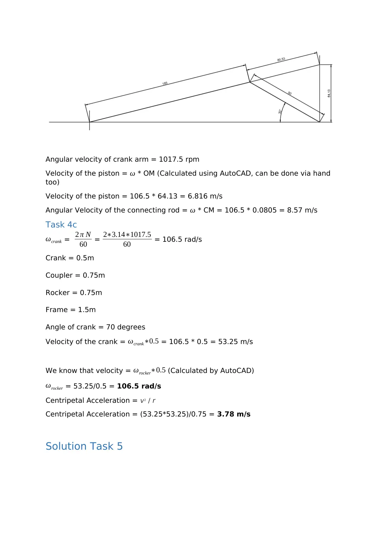
Angular velocity of crank arm = 1017.5 rpm
Velocity of the piston = ω * OM (Calculated using AutoCAD, can be done via hand
too)
Velocity of the piston = 106.5 * 64.13 = 6.816 m/s
Angular Velocity of the connecting rod = ω * CM = 106.5 * 0.0805 = 8.57 m/s
Task 4c
ωcrank = 2 π N
60 = 2∗3.14∗1017.5
60 = 106.5 rad/s
Crank = 0.5m
Coupler = 0.75m
Rocker = 0.75m
Frame = 1.5m
Angle of crank = 70 degrees
Velocity of the crank = ωcrank∗0.5 = 106.5 * 0.5 = 53.25 m/s
We know that velocity = ωrocker∗0.5 (Calculated by AutoCAD)
ωrocker = 53.25/0.5 = 106.5 rad/s
Centripetal Acceleration = v2 / r
Centripetal Acceleration = (53.25*53.25)/0.75 = 3.78 m/s
Solution Task 5
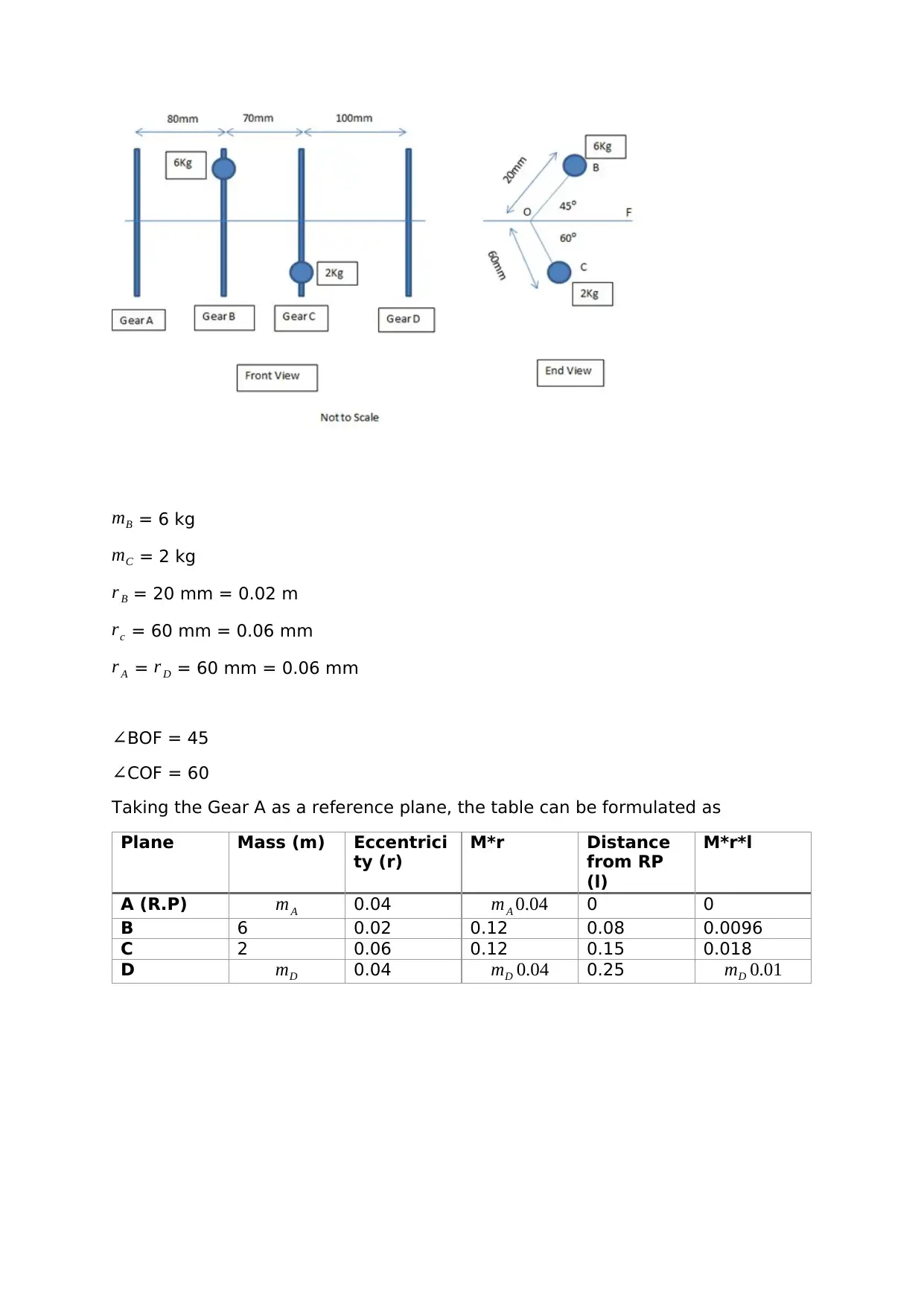
mB = 6 kg
mC = 2 kg
r B = 20 mm = 0.02 m
rc = 60 mm = 0.06 mm
r A = r D = 60 mm = 0.06 mm
∠BOF = 45
∠COF = 60
Taking the Gear A as a reference plane, the table can be formulated as
Plane Mass (m) Eccentrici
ty (r)
M*r Distance
from RP
(l)
M*r*l
A (R.P) mA 0.04 mA 0.04 0 0
B 6 0.02 0.12 0.08 0.0096
C 2 0.06 0.12 0.15 0.018
D mD 0.04 mD 0.04 0.25 mD 0.01
⊘ This is a preview!⊘
Do you want full access?
Subscribe today to unlock all pages.
Trusted by 1+ million students worldwide
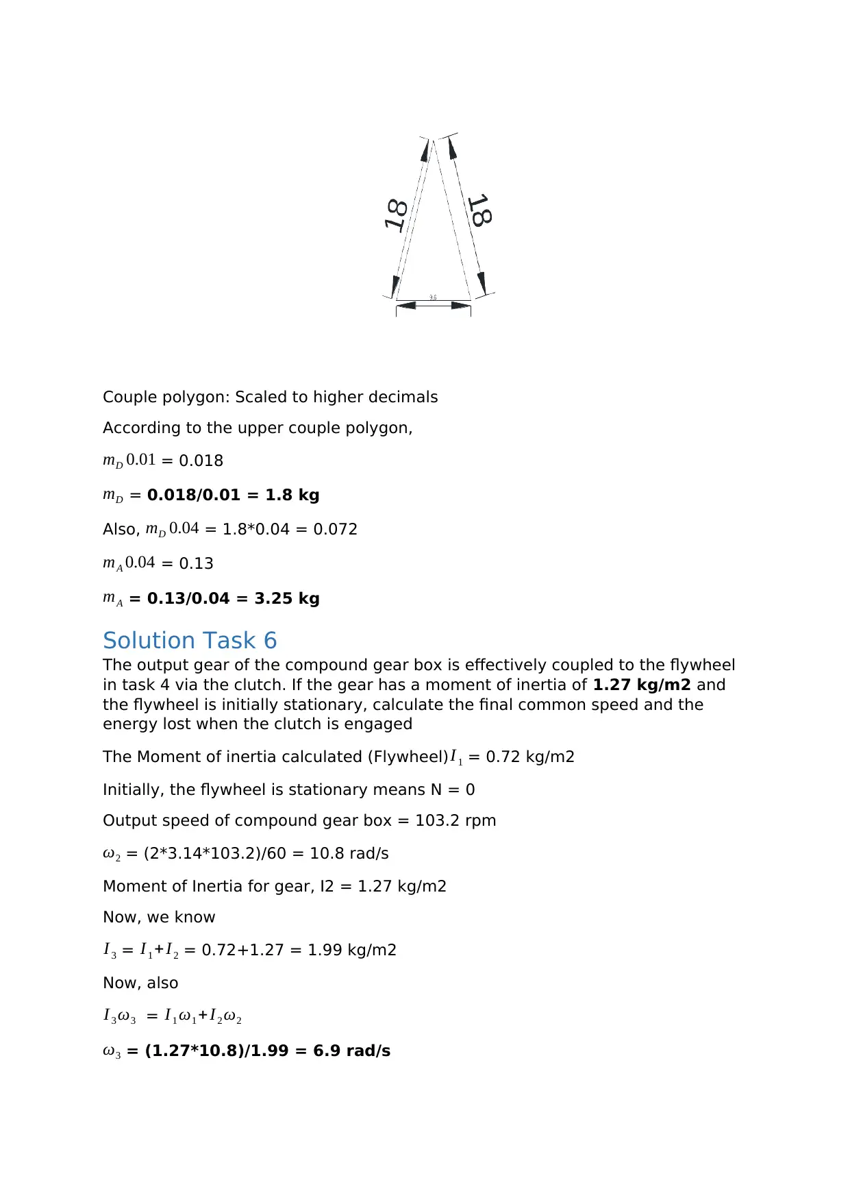
Couple polygon: Scaled to higher decimals
According to the upper couple polygon,
mD 0.01 = 0.018
mD = 0.018/0.01 = 1.8 kg
Also, mD 0.04 = 1.8*0.04 = 0.072
mA 0.04 = 0.13
mA = 0.13/0.04 = 3.25 kg
Solution Task 6
The output gear of the compound gear box is effectively coupled to the flywheel
in task 4 via the clutch. If the gear has a moment of inertia of 1.27 kg/m2 and
the flywheel is initially stationary, calculate the final common speed and the
energy lost when the clutch is engaged
The Moment of inertia calculated (Flywheel) I 1 = 0.72 kg/m2
Initially, the flywheel is stationary means N = 0
Output speed of compound gear box = 103.2 rpm
ω2 = (2*3.14*103.2)/60 = 10.8 rad/s
Moment of Inertia for gear, I2 = 1.27 kg/m2
Now, we know
I 3 = I 1 +I 2 = 0.72+1.27 = 1.99 kg/m2
Now, also
I 3 ω3 = I 1 ω1 + I 2 ω2
ω3 = (1.27*10.8)/1.99 = 6.9 rad/s
Paraphrase This Document
Need a fresh take? Get an instant paraphrase of this document with our AI Paraphraser
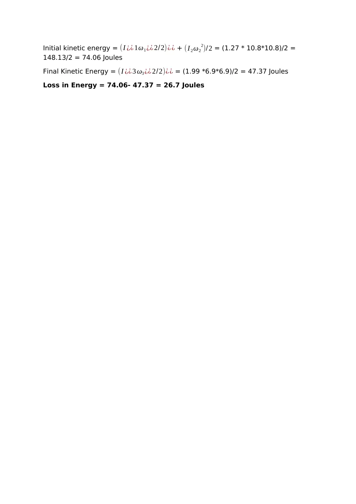
Initial kinetic energy = (I ¿¿ 1ω1 ¿¿ 2/2) ¿ ¿ + ( I2 ω2
2)/2 = (1.27 * 10.8*10.8)/2 =
148.13/2 = 74.06 Joules
Final Kinetic Energy = (I ¿¿ 3 ω3 ¿¿ 2/2)¿ ¿ = (1.99 *6.9*6.9)/2 = 47.37 Joules
Loss in Energy = 74.06- 47.37 = 26.7 Joules
2)/2 = (1.27 * 10.8*10.8)/2 =
148.13/2 = 74.06 Joules
Final Kinetic Energy = (I ¿¿ 3 ω3 ¿¿ 2/2)¿ ¿ = (1.99 *6.9*6.9)/2 = 47.37 Joules
Loss in Energy = 74.06- 47.37 = 26.7 Joules
1 out of 11

Your All-in-One AI-Powered Toolkit for Academic Success.
+13062052269
info@desklib.com
Available 24*7 on WhatsApp / Email
![[object Object]](/_next/static/media/star-bottom.7253800d.svg)
Unlock your academic potential
© 2024 | Zucol Services PVT LTD | All rights reserved.