Mechanical Services Engineering Design: Air Conditioning & Duct Design
VerifiedAdded on 2023/06/03
|13
|1237
|329
Practical Assignment
AI Summary
This assignment presents a comprehensive mechanical services engineering design for an office building located in South Brisbane, Queensland. The design focuses on the air conditioning system and ductwork for Level 10 of the building. The assignment begins with deriving the heat load, consi...
Mechanical Services Engineering Design
The Air conditioning and Duct design
Prepared and Done by:
Submission Details:
The Air conditioning and Duct design
Prepared and Done by:
Submission Details:
Paraphrase This Document
Need a fresh take? Get an instant paraphrase of this document with our AI Paraphraser
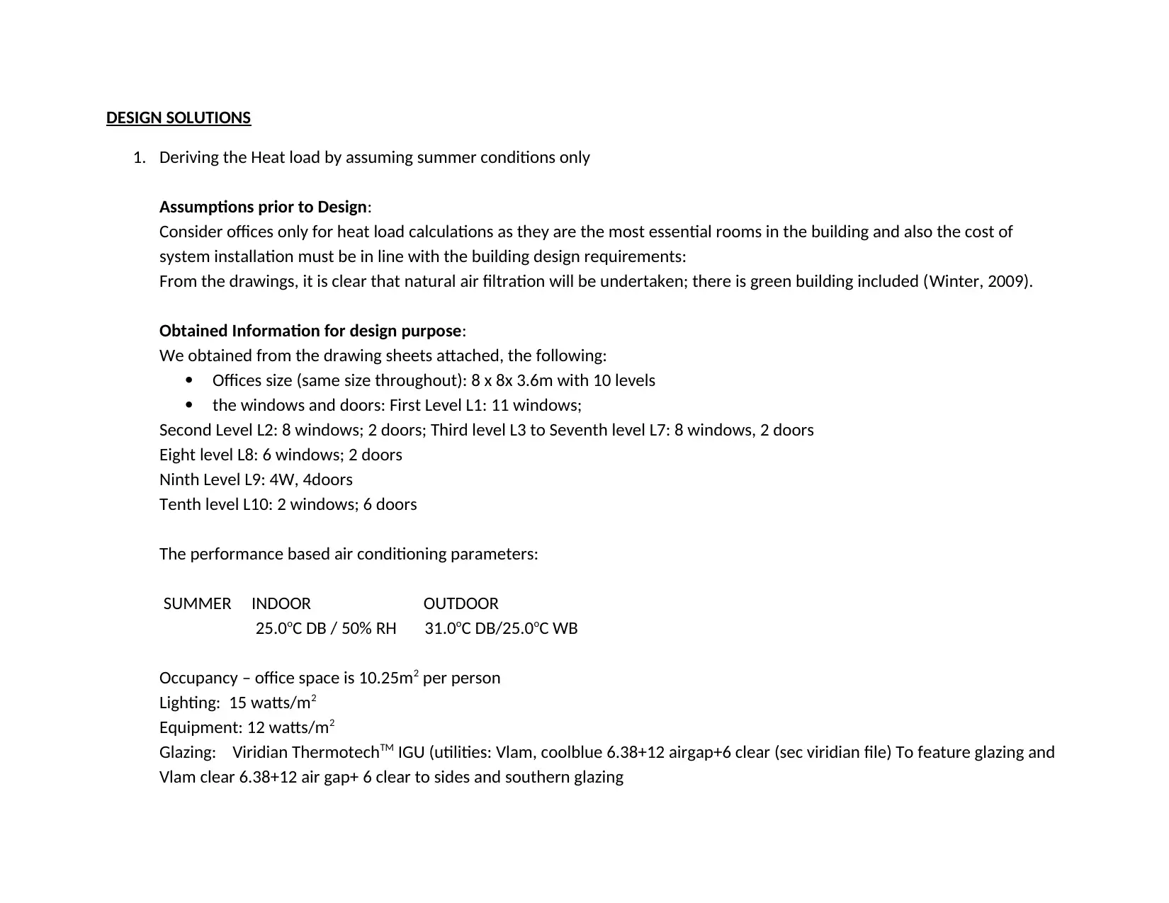
DESIGN SOLUTIONS
1. Deriving the Heat load by assuming summer conditions only
Assumptions prior to Design:
Consider offices only for heat load calculations as they are the most essential rooms in the building and also the cost of
system installation must be in line with the building design requirements:
From the drawings, it is clear that natural air filtration will be undertaken; there is green building included (Winter, 2009).
Obtained Information for design purpose:
We obtained from the drawing sheets attached, the following:
Offices size (same size throughout): 8 x 8x 3.6m with 10 levels
the windows and doors: First Level L1: 11 windows;
Second Level L2: 8 windows; 2 doors; Third level L3 to Seventh level L7: 8 windows, 2 doors
Eight level L8: 6 windows; 2 doors
Ninth Level L9: 4W, 4doors
Tenth level L10: 2 windows; 6 doors
The performance based air conditioning parameters:
SUMMER INDOOR OUTDOOR
25.0oC DB / 50% RH 31.0oC DB/25.0oC WB
Occupancy – office space is 10.25m2 per person
Lighting: 15 watts/m2
Equipment: 12 watts/m2
Glazing: Viridian ThermotechTM IGU (utilities: Vlam, coolblue 6.38+12 airgap+6 clear (sec viridian file) To feature glazing and
Vlam clear 6.38+12 air gap+ 6 clear to sides and southern glazing
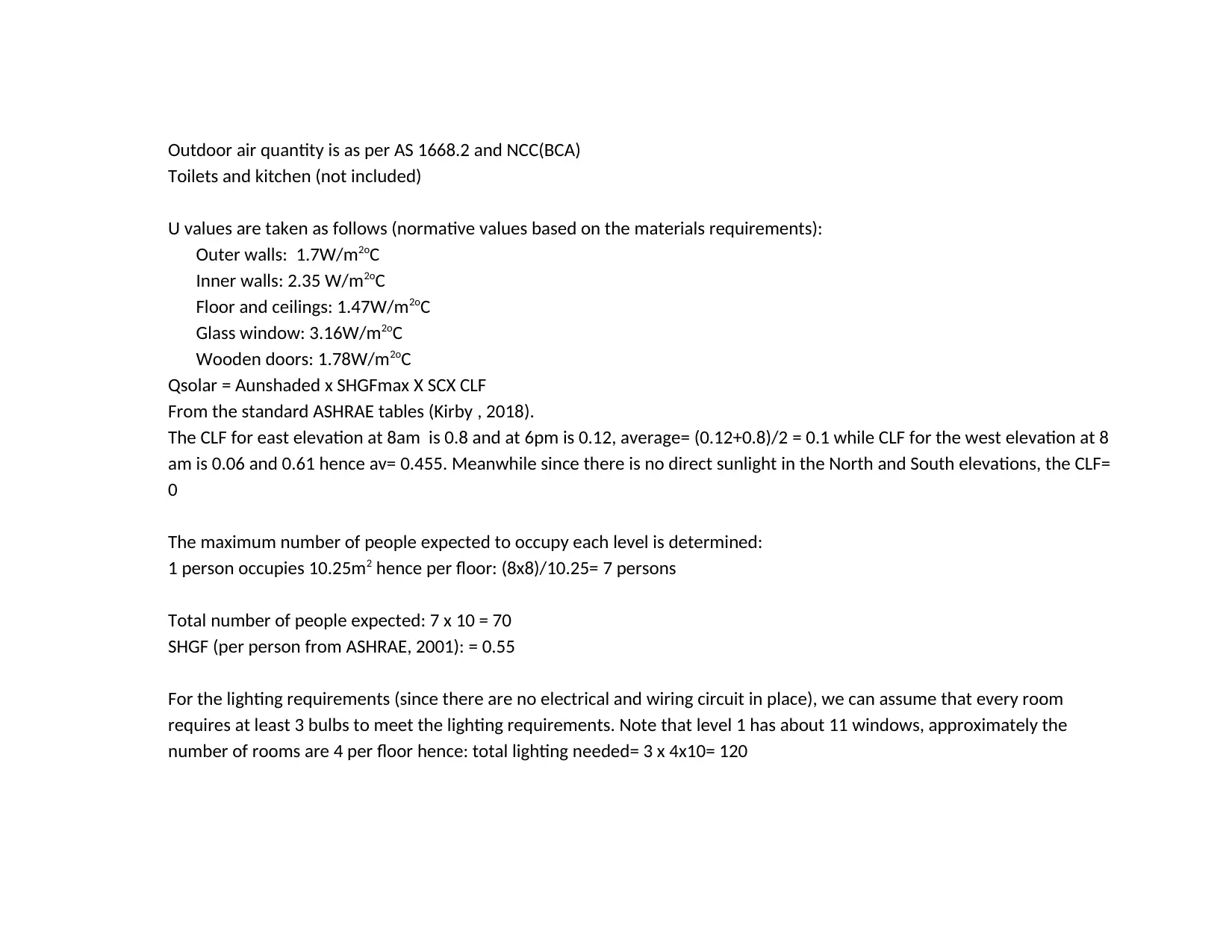
Outdoor air quantity is as per AS 1668.2 and NCC(BCA)
Toilets and kitchen (not included)
U values are taken as follows (normative values based on the materials requirements):
Outer walls: 1.7W/m2oC
Inner walls: 2.35 W/m2oC
Floor and ceilings: 1.47W/m2oC
Glass window: 3.16W/m2oC
Wooden doors: 1.78W/m2oC
Qsolar = Aunshaded x SHGFmax X SCX CLF
From the standard ASHRAE tables (Kirby , 2018).
The CLF for east elevation at 8am is 0.8 and at 6pm is 0.12, average= (0.12+0.8)/2 = 0.1 while CLF for the west elevation at 8
am is 0.06 and 0.61 hence av= 0.455. Meanwhile since there is no direct sunlight in the North and South elevations, the CLF=
0
The maximum number of people expected to occupy each level is determined:
1 person occupies 10.25m2 hence per floor: (8x8)/10.25= 7 persons
Total number of people expected: 7 x 10 = 70
SHGF (per person from ASHRAE, 2001): = 0.55
For the lighting requirements (since there are no electrical and wiring circuit in place), we can assume that every room
requires at least 3 bulbs to meet the lighting requirements. Note that level 1 has about 11 windows, approximately the
number of rooms are 4 per floor hence: total lighting needed= 3 x 4x10= 120
⊘ This is a preview!⊘
Do you want full access?
Subscribe today to unlock all pages.

Trusted by 1+ million students worldwide
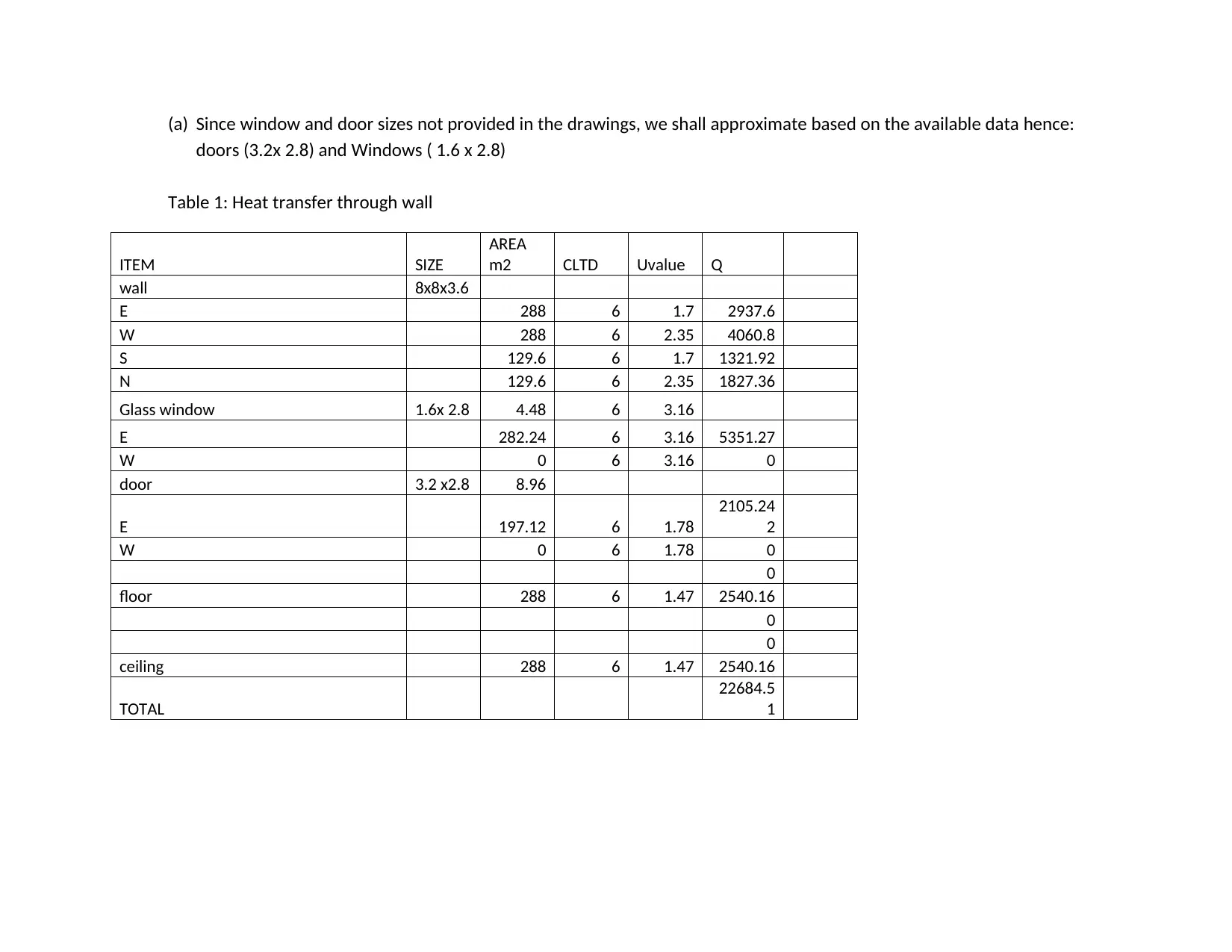
(a) Since window and door sizes not provided in the drawings, we shall approximate based on the available data hence:
doors (3.2x 2.8) and Windows ( 1.6 x 2.8)
Table 1: Heat transfer through wall
ITEM SIZE
AREA
m2 CLTD Uvalue Q
wall 8x8x3.6
E 288 6 1.7 2937.6
W 288 6 2.35 4060.8
S 129.6 6 1.7 1321.92
N 129.6 6 2.35 1827.36
Glass window 1.6x 2.8 4.48 6 3.16
E 282.24 6 3.16 5351.27
W 0 6 3.16 0
door 3.2 x2.8 8.96
E 197.12 6 1.78
2105.24
2
W 0 6 1.78 0
0
floor 288 6 1.47 2540.16
0
0
ceiling 288 6 1.47 2540.16
TOTAL
22684.5
1
Paraphrase This Document
Need a fresh take? Get an instant paraphrase of this document with our AI Paraphraser
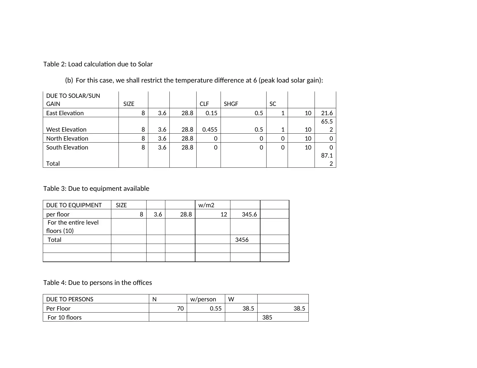
Table 2: Load calculation due to Solar
(b) For this case, we shall restrict the temperature difference at 6 (peak load solar gain):
DUE TO SOLAR/SUN
GAIN SIZE CLF SHGF SC
East Elevation 8 3.6 28.8 0.15 0.5 1 10 21.6
West Elevation 8 3.6 28.8 0.455 0.5 1 10
65.5
2
North Elevation 8 3.6 28.8 0 0 0 10 0
South Elevation 8 3.6 28.8 0 0 0 10 0
Total
87.1
2
Table 3: Due to equipment available
DUE TO EQUIPMENT SIZE w/m2
per floor 8 3.6 28.8 12 345.6
For the entire level
floors (10)
Total 3456
Table 4: Due to persons in the offices
DUE TO PERSONS N w/person W
Per Floor 70 0.55 38.5 38.5
For 10 floors 385
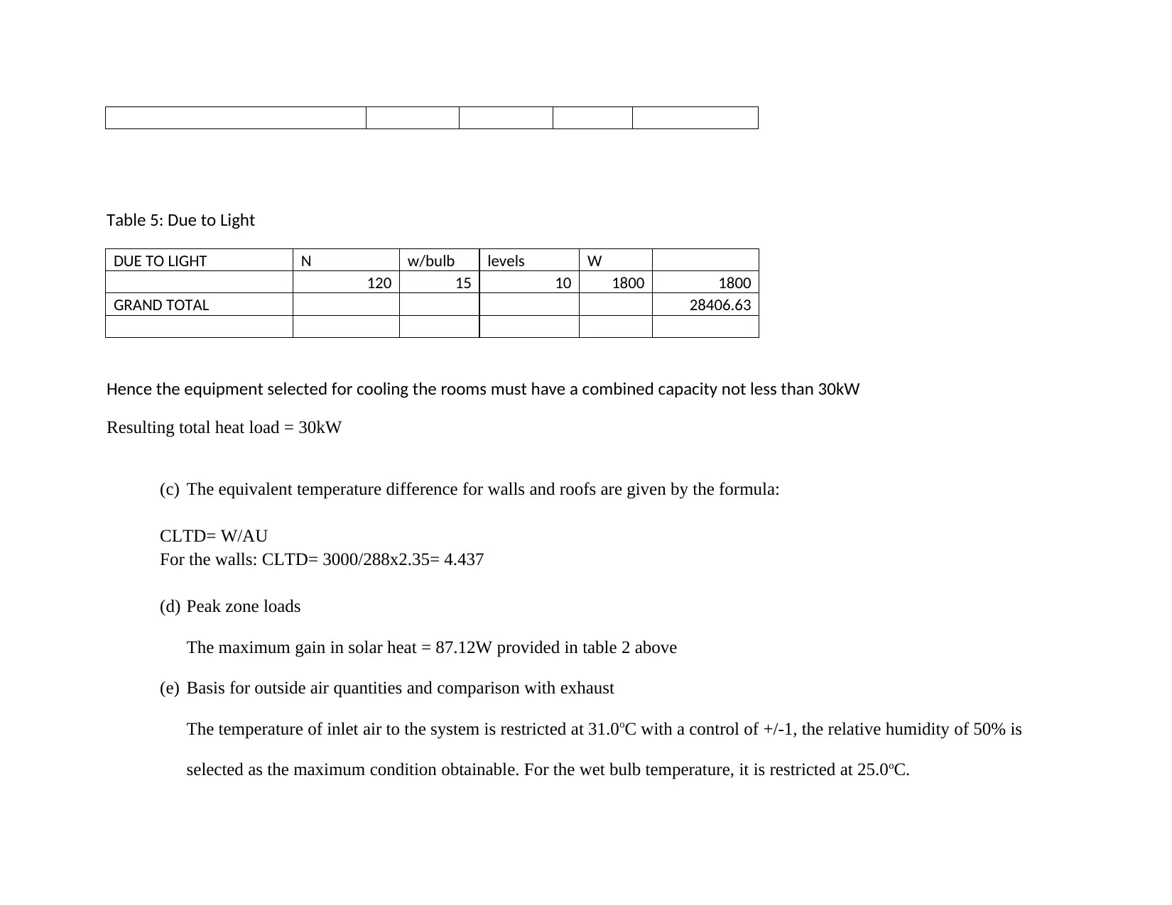
Table 5: Due to Light
DUE TO LIGHT N w/bulb levels W
120 15 10 1800 1800
GRAND TOTAL 28406.63
Hence the equipment selected for cooling the rooms must have a combined capacity not less than 30kW
Resulting total heat load = 30kW
(c) The equivalent temperature difference for walls and roofs are given by the formula:
CLTD= W/AU
For the walls: CLTD= 3000/288x2.35= 4.437
(d) Peak zone loads
The maximum gain in solar heat = 87.12W provided in table 2 above
(e) Basis for outside air quantities and comparison with exhaust
The temperature of inlet air to the system is restricted at 31.0oC with a control of +/-1, the relative humidity of 50% is
selected as the maximum condition obtainable. For the wet bulb temperature, it is restricted at 25.0oC.
⊘ This is a preview!⊘
Do you want full access?
Subscribe today to unlock all pages.

Trusted by 1+ million students worldwide
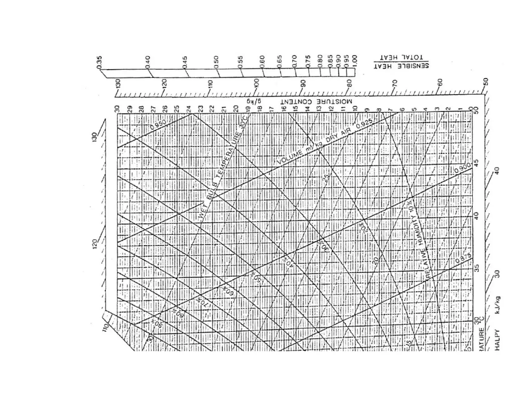
2. Psychrometrics and Equipment selection:
(a) Plot the psychometrics chart
(a) Plot the psychometrics chart
Paraphrase This Document
Need a fresh take? Get an instant paraphrase of this document with our AI Paraphraser
(b) Select air conditioning equipment (Manufacturer’s catalogue):
Based on the cooling load determined above, and from Shenglintec (2018) commercially available equipments, we select an
air handling unit with cooling capacity between 7.5kW to 93.6kW using R22 refrigerant
Based on the cooling load determined above, and from Shenglintec (2018) commercially available equipments, we select an
air handling unit with cooling capacity between 7.5kW to 93.6kW using R22 refrigerant
⊘ This is a preview!⊘
Do you want full access?
Subscribe today to unlock all pages.

Trusted by 1+ million students worldwide
Paraphrase This Document
Need a fresh take? Get an instant paraphrase of this document with our AI Paraphraser
3. Duct work design
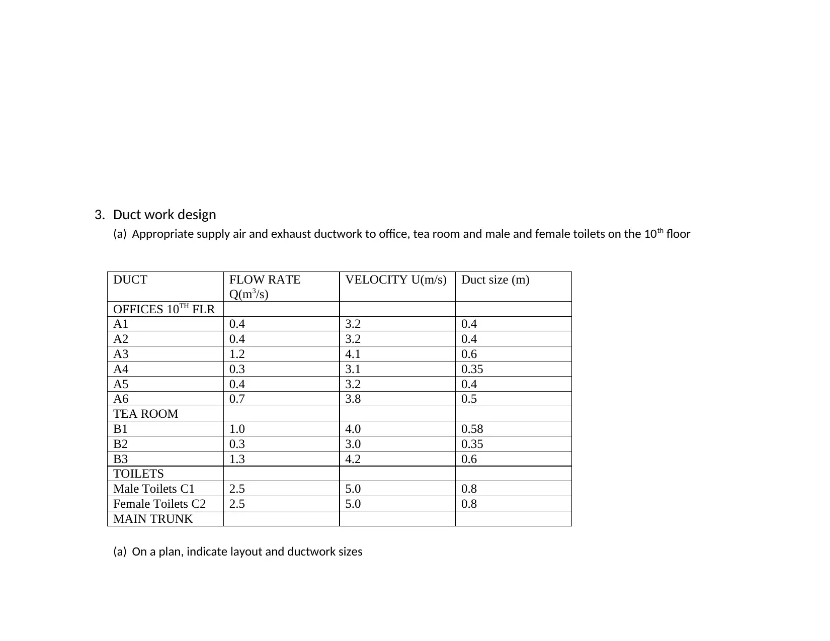
(a) Appropriate supply air and exhaust ductwork to office, tea room and male and female toilets on the 10th floor
DUCT FLOW RATE
Q(m3/s)
VELOCITY U(m/s) Duct size (m)
OFFICES 10TH FLR
A1 0.4 3.2 0.4
A2 0.4 3.2 0.4
A3 1.2 4.1 0.6
A4 0.3 3.1 0.35
A5 0.4 3.2 0.4
A6 0.7 3.8 0.5
TEA ROOM
B1 1.0 4.0 0.58
B2 0.3 3.0 0.35
B3 1.3 4.2 0.6
TOILETS
Male Toilets C1 2.5 5.0 0.8
Female Toilets C2 2.5 5.0 0.8
MAIN TRUNK
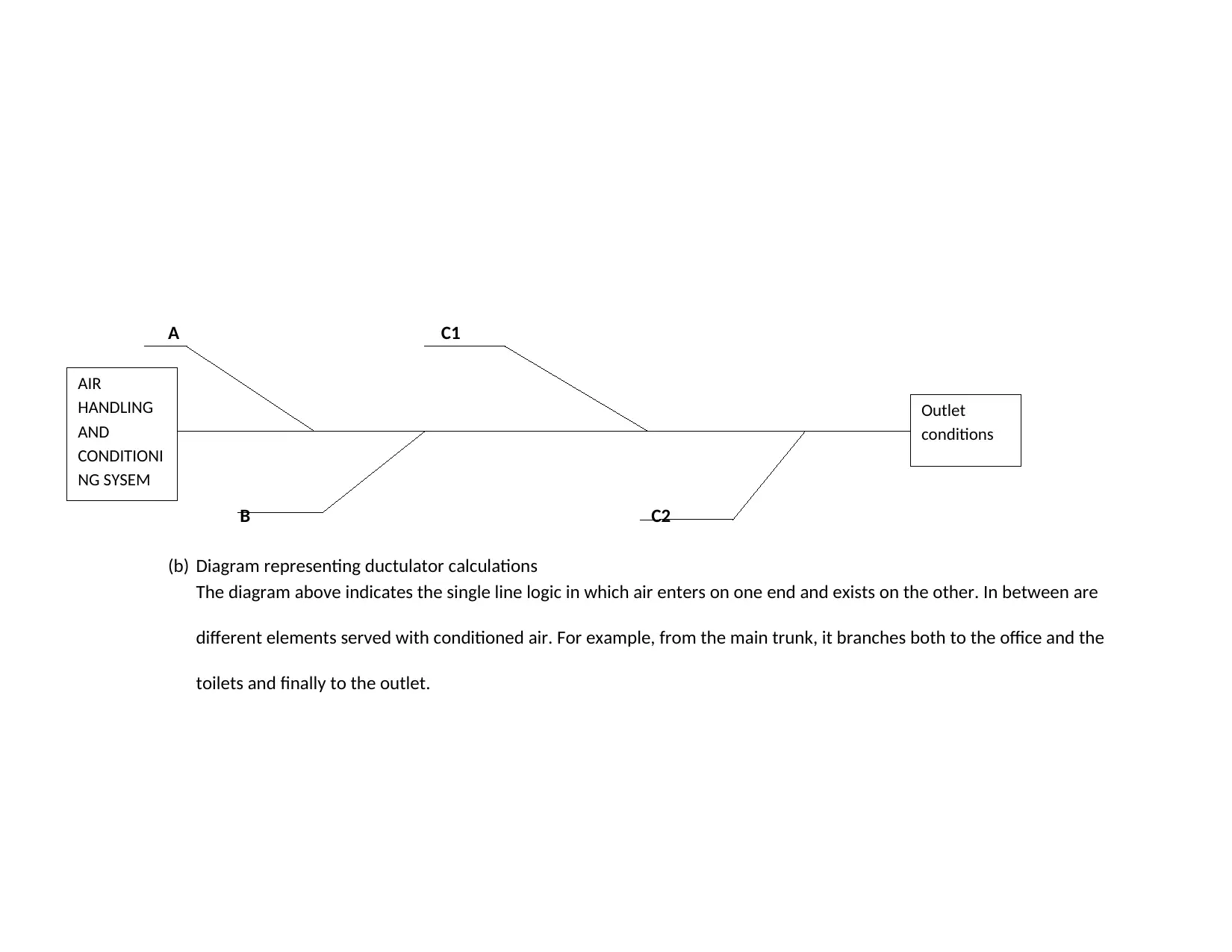
(a) On a plan, indicate layout and ductwork sizes
A C1
B C2
(b) Diagram representing ductulator calculations
The diagram above indicates the single line logic in which air enters on one end and exists on the other. In between are
different elements served with conditioned air. For example, from the main trunk, it branches both to the office and the
toilets and finally to the outlet.
AIR
HANDLING
AND
CONDITIONI
NG SYSEM
Outlet
conditions
⊘ This is a preview!⊘
Do you want full access?
Subscribe today to unlock all pages.

Trusted by 1+ million students worldwide

REFERENCE
Kirby ,R. (2018). Building Services Engineering Programme. Revised : Dr C König. Department of Mechanical Engineering: Brunel
University London.
Winter, S. (2009). ImprovingVentilation in Existing or New Buildings with Central Roof Exhaust. National Center for Healthy Housing.
Shenglintec. (2018). Shanghai Shenglin M& E Technology Company: Commercial catalogue. Available at:
www.shenglintec.com/m_products [accessed on: 15th October 2018].
1 out of 13
Your All-in-One AI-Powered Toolkit for Academic Success.
+13062052269
info@desklib.com
Available 24*7 on WhatsApp / Email
![[object Object]](/_next/static/media/star-bottom.7253800d.svg)
Unlock your academic potential
© 2024 | Zucol Services PVT LTD | All rights reserved.