Mechanical System Analysis: Stress, Strain, and Deflection

Verified

Added on  2023/01/10

|8
|578
|76
Homework Assignment
AI Summary
Document Page
Running head: MECHANICAL SYSTEM
MECHANICAL SYSTEM
Name of Student
Institution Affiliation
tabler-icon-diamond-filled.svg

Paraphrase This Document

Need a fresh take? Get an instant paraphrase of this document with our AI Paraphraser
Document Page
MECHANICAL SYSTEM
2
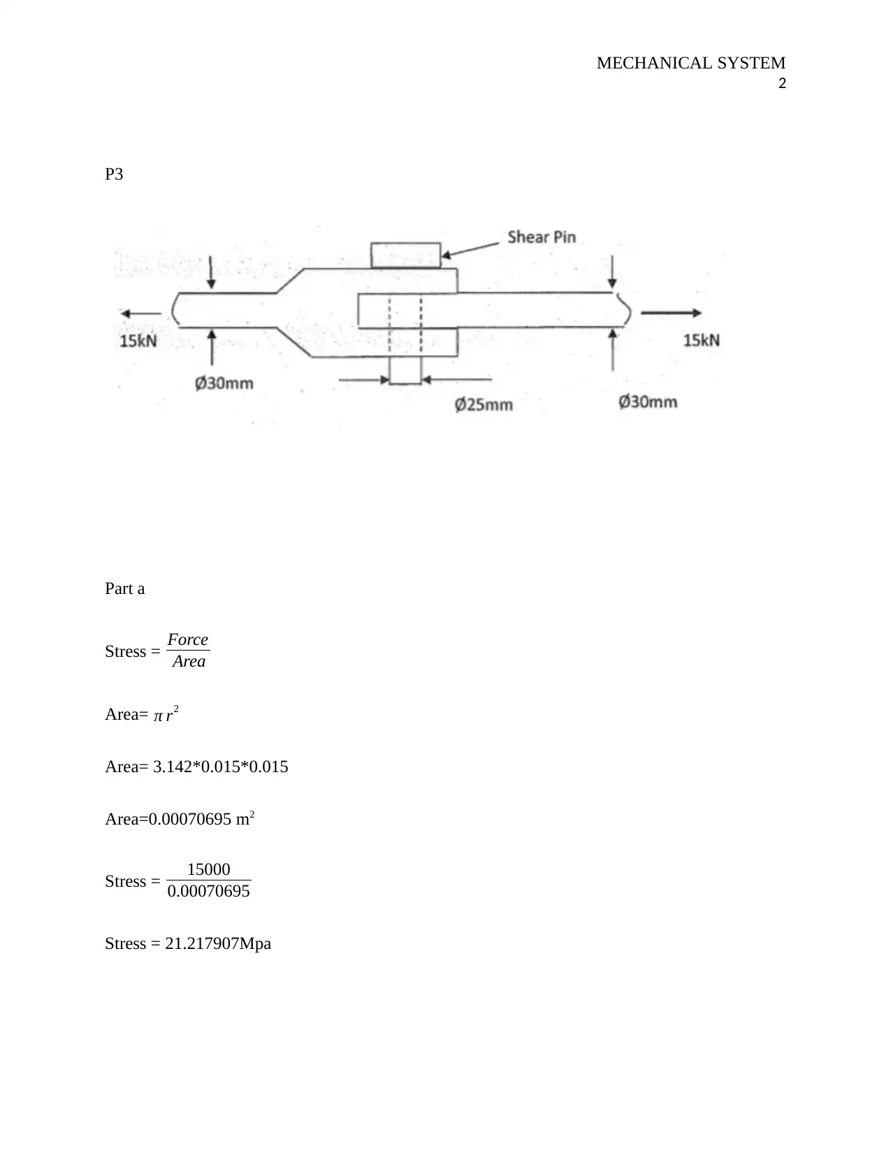
P3
Part a
Stress = Force
Area
Area= π r2
Area= 3.142*0.015*0.015
Area=0.00070695 m2
Stress = 15000
0.00070695
Stress = 21.217907Mpa
Document Page
MECHANICAL SYSTEM
3
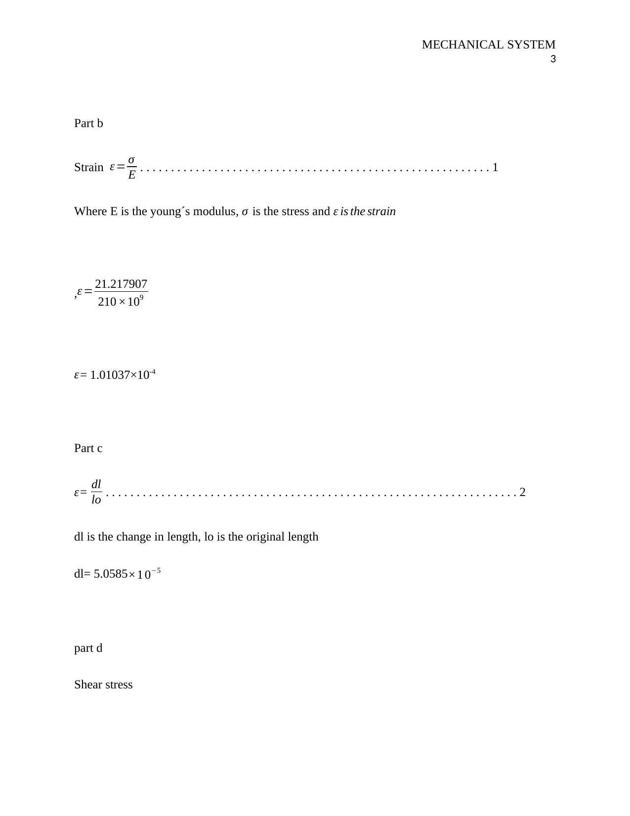
Part b
Strain ε = σ
E . . . . . . . . . . . . . . . . . . . . . . . . . . . . . . . . . . . . . . . . . . . . . . . . . . . . . . . . . 1
Where E is the young´s modulus, σ is the stress and ε is the strain
,ε = 21.217907
210 ×109
ε= 1.01037×10⁻⁴
Part c
ε= dl
lo . . . . . . . . . . . . . . . . . . . . . . . . . . . . . . . . . . . . . . . . . . . . . . . . . . . . . . . . . . . . . . . . . . . 2
dl is the change in length, lo is the original length
dl= 5.0585×1 05
part d
Shear stress
Document Page
MECHANICAL SYSTEM
4
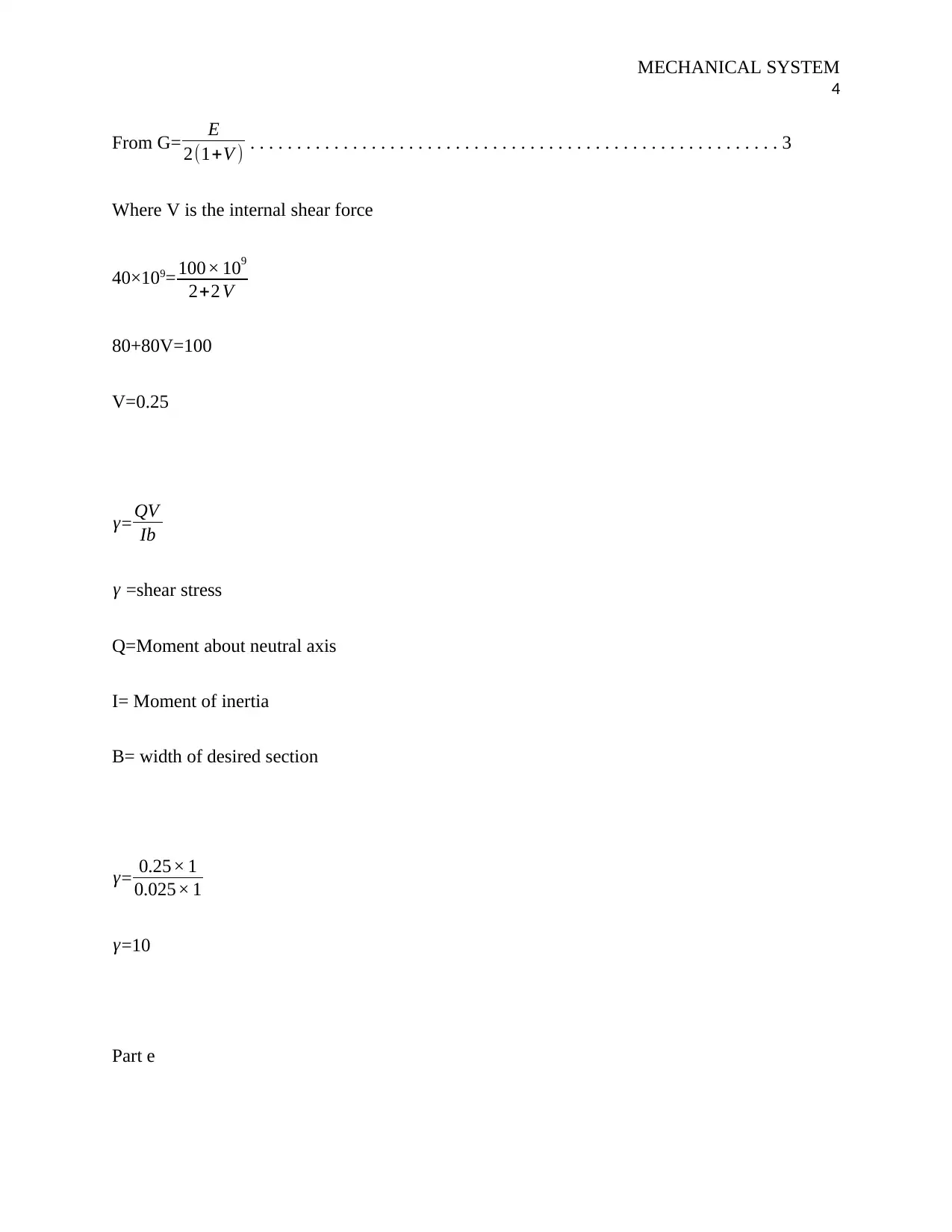
From G= E
2(1+V ) . . . . . . . . . . . . . . . . . . . . . . . . . . . . . . . . . . . . . . . . . . . . . . . . . . . . . . . . . 3
Where V is the internal shear force
40×109= 100× 109
2+2 V
80+80V=100
V=0.25
γ= QV
Ib
γ =shear stress
Q=Moment about neutral axis
I= Moment of inertia
B= width of desired section
γ= 0.25× 1
0.025× 1
γ=10
Part e
tabler-icon-diamond-filled.svg

Paraphrase This Document

Need a fresh take? Get an instant paraphrase of this document with our AI Paraphraser
Document Page
MECHANICAL SYSTEM
5
Strain shear
γ= τ
G
10= τ
40 ×109
τ =400×109
Part f
Angel of deflection
W=Load on beam
L=length of beam
E=young`s modulus
I=moments of inertia
θ= wl
2 E l2
L=0.5m
W= 15000
E=210Gpy
Document Page
MECHANICAL SYSTEM
6
I=0.0001
θ= 15000 × 0.5
2× 210× 109 ×0.000 12
θ= 7500
4200
θ=1.780
Task 10
Part a
Factor of safety
F.S = ultimate stress
allowable tention stress
Stress = force
area
Area =π r2
Document Page
MECHANICAL SYSTEM
7
=3.142×0.0082
=0.000201088
Stress = 35000
0.000201088
σ =174.053Mpa
F.S= 500
174.053
F.S=2.872
F.S= ultimate share stress
allowable stress
Allowable stress
τ = 24000
0.000201088
= 119.3 5 Mpa
F.S= 300
119.35
F.S= 2.513
Part b
From this we can see that the allowable stress is 119.35 Mpa and the ultimate shear stress of the
bolt is 300MPa. So failure is most likely in shear. This can be further illustrated from the
tabler-icon-diamond-filled.svg

Paraphrase This Document

Need a fresh take? Get an instant paraphrase of this document with our AI Paraphraser
Document Page
MECHANICAL SYSTEM
8
resultant factor of safety which is less as compared to the factors of safety in tension. For the
tension ultimate stress is 500 while the allowable stress is174.053. This gives the factor of safety
to be 2.872 which is more than that of the shear. Hence the failure is likely to occur in the shear
stress which has less than 1 factor of safety (Shama, 2010).
References
Bansal, K. (2010). A Textbook of Strength of Materials. Hull: Laxmi Publications.
Hansen, E. (2010). Strain Facies. London: Springer Science & Business Media.
Huang, T.-a. (2011). Time-dependent First Normal Stress Difference and Shear Stress Generated by
Polymer Melts in Steady Shear Flow. Hull: University of Wisconsin.
Kanda, T. (2010). Strain Hardening Cement Composites: Structural Design and Performance: State-of-
the-Art Report of the RILEM Technical Committee 208-HFC, SC3. Stoke: Springer Science &
Business Media.
Kolitawong, C. (2010). Local Shear Stress Transduction in Sliding Plate Rheometry. Stoke: University of
Wisconsin--Madison.
Schwartz, M. (2012). Basic Engineering for Builders. Liverpool: Craftsman Book Company.
Shama, M. (2010). Torsion and Shear Stresses in Ships. Chicago: Springer Science & Business Media.
Toro, G. D. (2010). The Strain. Liverpool: HarperCollins.
chevron_up_icon
1 out of 8
circle_padding
hide_on_mobile
zoom_out_icon
[object Object]