Comprehensive Analysis of Beam Deflection in Structural Mechanics
VerifiedAdded on 2020/04/07
|16
|2068
|303
Practical Assignment
AI Summary
This document provides a detailed analysis of beam deflection under various loading conditions and support configurations. It explores concepts such as moment of inertia, elastic curves, and the equations for slope and deflection. The assignment includes step-by-step calculations for multiple bea...
Mechanics of Structure 1
MECHANICS OF STRUCTURE
Name
Course
Professor
University
City/state
Date
MECHANICS OF STRUCTURE
Name
Course
Professor
University
City/state
Date
Paraphrase This Document
Need a fresh take? Get an instant paraphrase of this document with our AI Paraphraser
Mechanics of Structure 2
Beam deflection 01
Linearly distributed load, w0 = 3 kN/m
E = 270 GPa, b = 200 mm and h = 400 mm
Moment of inertia, I = bh ³
12 = 200 x 400³
12 = 1.0667 x 109 mm4 (The Engineering ToolBox, (n.d.))
EI = 270 GPa x 1.0667 x 109 mm4 = 270 x 103 N/mm2 x 1.0667 x 109 mm4 = 2.88 x 10¹⁴ Nmm2
Taking moments at B to the left hand side:
∑ MB=0 → -RAL + ( woL
2 ¿( L
3 ) = 0
RAL = woL ²
6 → RA = woL
6 ; and RB = w 0 L
3
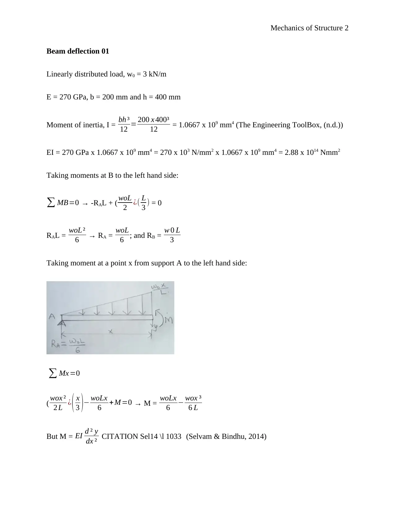
Taking moment at a point x from support A to the left hand side:
∑ Mx =0
( wox ²
2 L ¿ ( x
3 )− woLx
6 +M =0 → M = woLx
6 − wox ³
6 L
But M = EI d ² y
dx ² CITATION Sel14 \l 1033 (Selvam & Bindhu, 2014)
Mechanics of Structure 3
Therefore
EI d ² y
dx ² = woLx
6 − wox ³
6 L …………………………………………………………… (1)
Integrating equation 1 with respect to x gives
EI dy
dx = woLx ²
12 − wo x4
24 L +C 1 ………………………………………………… (2)
Integrating equation 2 with respect to x gives
EI y= woLx ³
36 − wo x5
120 L +C 1 x+C 2 ………………………………………. (3)
When x = 0, y = 0; substituting this in equation 3 gives:
0 = 0 – 0 + 0 + C2 → C2 = 0
When x = L, y = 0; substituting this in equation 3 gives:
0= woL⁴
36 − wo L4
120 + C 1 L+0 → C 1 L= wo L4
120 − woL ⁴
36 ; C1 = −7 woL ³
360
Substituting the value of C1 in equation 3 and making y the subject gives:
EI y= woLx ³
36 − wo x5
120 L − 7 woL ³ x
360
y= wo
EI [ L x3
36 − x5
120 L −7 L3 x
360 ] ………………………………………………. (4)
Equation 4 is the equation of the elastic curve
Slope of the curve is determined by differentiating equation 4 with respect to x, which gives:
⊘ This is a preview!⊘
Do you want full access?
Subscribe today to unlock all pages.

Trusted by 1+ million students worldwide
Mechanics of Structure 4
dy
dx = wo
EI [ L x2
12 − x4
24 L− 7 L3
360 ] ……………………….…………………….. (5)
At maximum deflection, slope, dy
dx =0 (substituting this in equation 5)
0 = 30L2x2 – 15x4 – 7L4 (where x is the point at maximum deflection)
15x4 – 30L2x2 + 7L4 = 0
Solving this equation gives x2 = 0.2697L2 → x = 0.5193L
Thus maximum deflection is:
y= wo
EI [ L(0.5193 L) ³
36 −(0.5193 L)⁵
120 L −7 L3 (0.5193 L)
360 ]
y= wo
EI [ 0.14 L⁴
36 − 0.0378 L ⁴
120 −3.6352 L ⁴
360 ]
y= wo
EI [ 1.4 L4−0.1134 L4−3.6352 L ⁴
360 ]
y= wo
EI [−2.3486 L4
360 ]
y= wo
EI [−0.006524 L ⁴]
y=0.006524 woL ⁴
EI (ignore the negative sign) …………………………………….. (6)
Equation 6 is the maximum deflection of the beam
Substituting the values of E, I, w0 and L in equation 6
EI = 2.88 x 10¹⁴ Nmm2; w0 = 3 kN/m = 3 N/mm; L = L mm
Paraphrase This Document
Need a fresh take? Get an instant paraphrase of this document with our AI Paraphraser
Mechanics of Structure 5
y=0.006524[ 3 x L4
2.88 x 10¹⁴ ]
y = 6.796 x 10⁻¹⁷L4 mm (where L is the length of the beam in mm).
Beam deflection 02
E = 15 GPa, b = 200 mm and h = 400 mm
Moment of inertia, I = bh ³
12 = 200 x 400³
12 = 1.0667 x 109 mm4
EI = 15 GPa x 1.0667 x 109 mm4 = 15 x 103 N/mm2 x 1.0667 x 109 mm4 = 1.6 x 10¹³ Nmm2
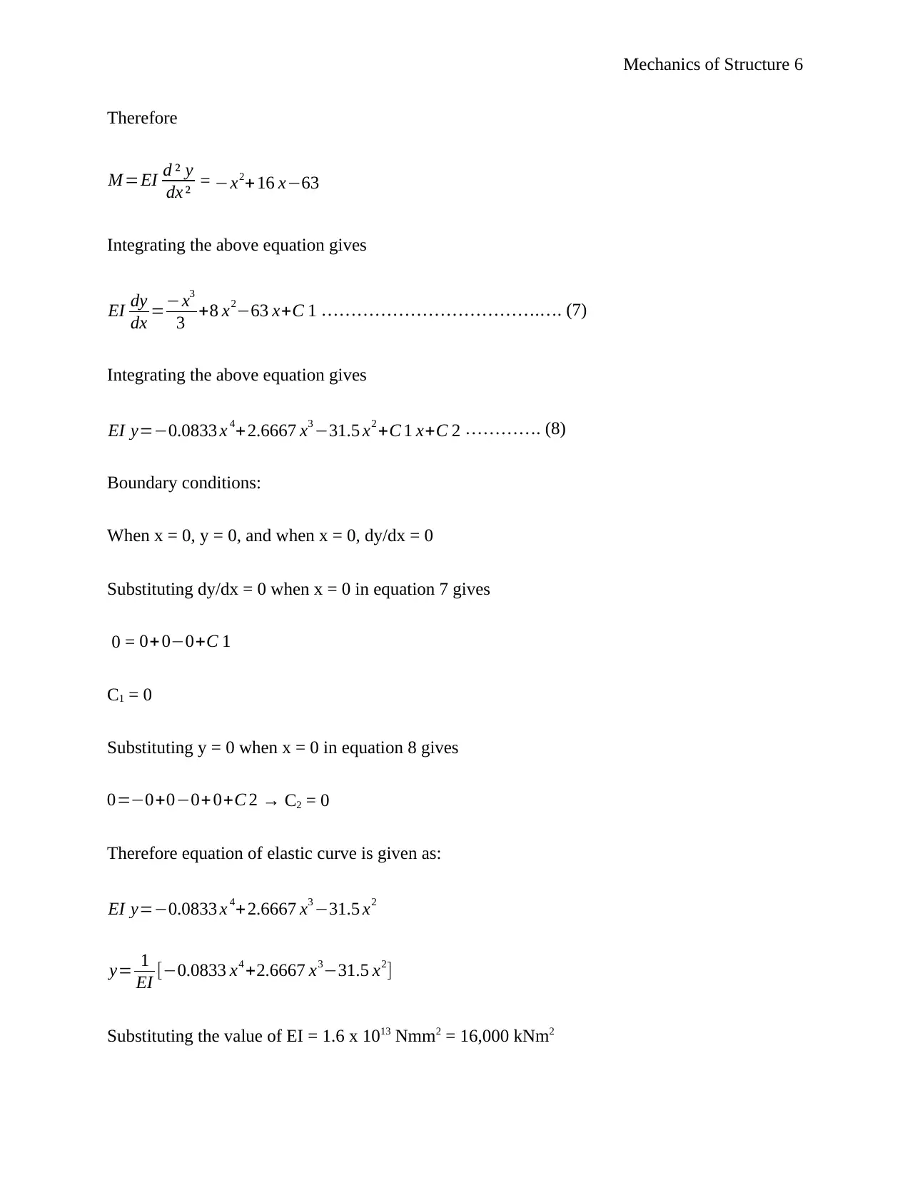
∑ Fy=0 → RA – (2 x 3) – 4 – 6 = 0; RA = 16 kN
∑ MA =0 → -MA + (2 x 3 x 1.5) + (4 x 4.5) + (6 x 6) = 0; MA = 63 kNm
Taking moments, M, at a point x from the left hand side
∑ MA =0; RAx – MA – ( 2 x2
2 ¿ = 0; 16x – 63 – x2 = 0
M = -x2 + 16x – 63 = 0
But M = EI d ² y
dx ² CITATION Sig17 \l 1033 (Sigurdardottir, et al., 2017)
Mechanics of Structure 6
Therefore
M =EI d ² y
dx ² = −x2+16 x−63
Integrating the above equation gives
EI dy
dx =−x3
3 +8 x2−63 x+C 1 ……………………………….…. (7)
Integrating the above equation gives
EI y=−0.0833 x 4+ 2.6667 x3 −31.5 x2 +C 1 x+C 2 …………. (8)
Boundary conditions:
When x = 0, y = 0, and when x = 0, dy/dx = 0
Substituting dy/dx = 0 when x = 0 in equation 7 gives
0 = 0+ 0−0+C 1
C1 = 0
Substituting y = 0 when x = 0 in equation 8 gives
0=−0+0−0+0+C 2 → C2 = 0
Therefore equation of elastic curve is given as:
EI y=−0.0833 x 4+ 2.6667 x3 −31.5 x2
y= 1
EI [−0.0833 x4 +2.6667 x3−31.5 x2]
Substituting the value of EI = 1.6 x 10¹³ Nmm2 = 16,000 kNm2
⊘ This is a preview!⊘
Do you want full access?
Subscribe today to unlock all pages.

Trusted by 1+ million students worldwide
Mechanics of Structure 7
y= 1
16,000 [−0.0833 x4 +2.6667 x3 −31.5 x2 ]
Beam deflection 03
Calculating support reactions:
Taking moments at B, ∑ MB=0
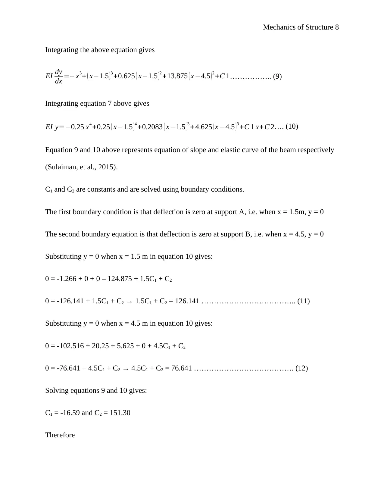
3RA + 20(1.5) – (6 x 1.5 x 3.75) = 0; 3RA = 3.75; RA = 1.25 kN
RB = [(6 x 1.5) + 20] = 1.25 = 27.75 kN
Taking moment at a point x along the beam
∑ Mx =0
M = −6
2 ( x−0 ) ²− (−6
2 ) ( x−1.5 )2− (−1.25 ) ( x−1.5 )−(−27.75)( x−4.5)
M = -3x2 + 3(x – 1.5)2 + 1.25(x – 1.5) + 27.75(x – 4.5)
But M = EI d ² y
dx ²
Therefore
M =EI d ² y
dx ² = -3x2 + 3(x – 1.5)2 + 1.25(x – 1.5) + 27.75(x – 4.5)
Paraphrase This Document
Need a fresh take? Get an instant paraphrase of this document with our AI Paraphraser
Mechanics of Structure 8
Integrating the above equation gives
EI dy
dx =−x3+ ( x−1.5 )3 +0.625 ( x−1.5 )2 +13.875 ( x −4.5 )2 +C 1…………….. (9)
Integrating equation 7 above gives
EI y=−0.25 x4 +0.25 ( x−1.5 ) 4 +0.2083 ( x−1.5 )3 + 4.625 ( x −4.5 ) 3 +C 1 x+ C 2…. (10)
Equation 9 and 10 above represents equation of slope and elastic curve of the beam respectively
(Sulaiman, et al., 2015).
C1 and C2 are constants and are solved using boundary conditions.
The first boundary condition is that deflection is zero at support A, i.e. when x = 1.5m, y = 0
The second boundary equation is that deflection is zero at support B, i.e. when x = 4.5, y = 0
Substituting y = 0 when x = 1.5 m in equation 10 gives:
0 = -1.266 + 0 + 0 – 124.875 + 1.5C1 + C2
0 = -126.141 + 1.5C1 + C2 → 1.5C1 + C2 = 126.141 ……………………………….. (11)
Substituting y = 0 when x = 4.5 m in equation 10 gives:
0 = -102.516 + 20.25 + 5.625 + 0 + 4.5C1 + C2
0 = -76.641 + 4.5C1 + C2 → 4.5C1 + C2 = 76.641 …………………………………. (12)
Solving equations 9 and 10 gives:
C1 = -16.59 and C2 = 151.30
Therefore
Mechanics of Structure 9
Equation of the slope is:
EI dy
dx =−x3+ ( x−1.5 )3 +0.625 ( x−1.5 )2 +13.875 ( x −4.5 )2 +C 1
dy
dx = 1
EI [−x3 + ( x−1.5 )3 +0.625 ( x−1.5 )2 +13.875 ( x−4.5 )2−16.59]
Equation of the elastic curve is:
EI y=−0.25 x4 +0.25 ( x−1.5 ) 4 +0.2083 ( x−1.5 )3 + 4.625 ( x −4.5 ) 3 +C 1 x+ C 2
y= 1
EI [−0.25 x4 +0.25 ( x−1.5 ) 4+ 0.2083 ( x −1.5 )3+ 4.625 ( x−4.5 )3−16.59 x+151.30]
Beam deflection 04
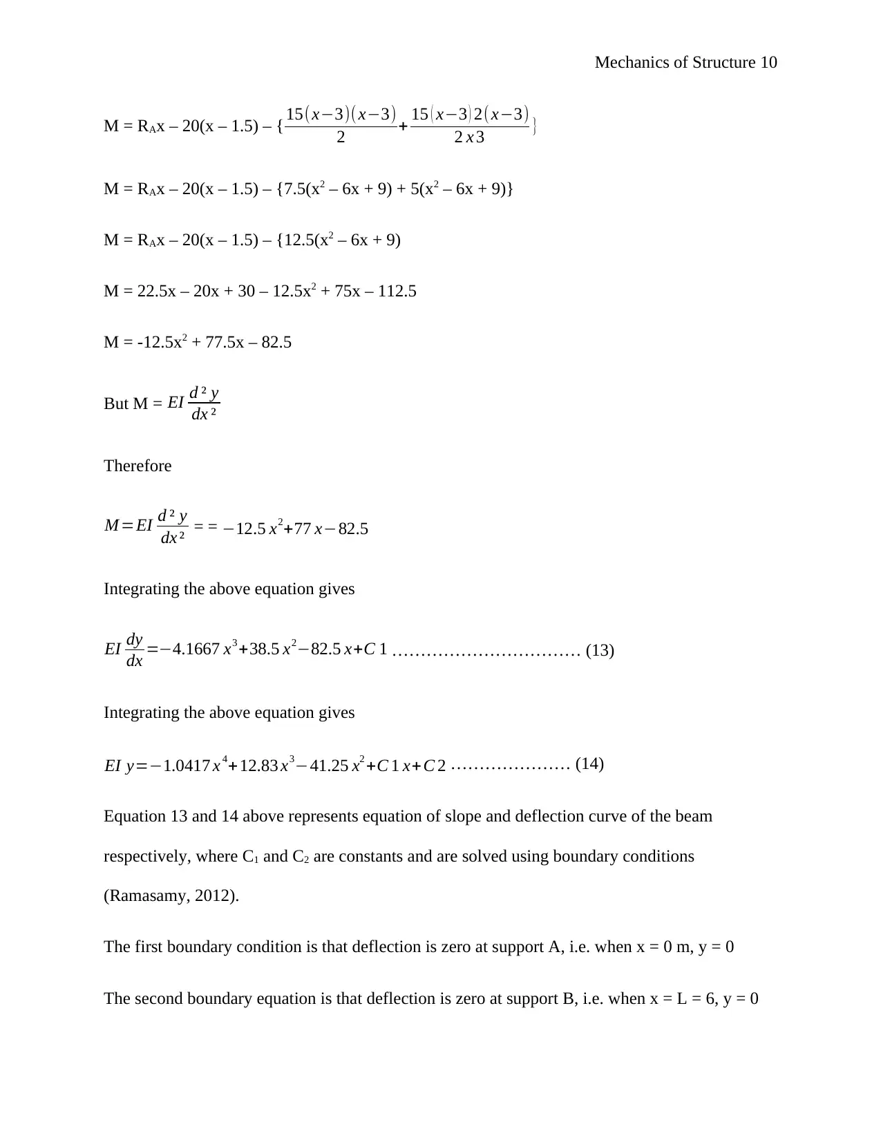
Finding support reactions:
Taking moments at B
∑ MB=0 → 6RA – 4.5(20) – ( 15 x 3 x 2 x 3
6 ¿ = 0; 6RA = 105; RA = 22.5 kN
RB = (20 + ( 15 x 3
2 ¿ – 22.5 = 20 kN
Taking moments at a point x from point A near point B to the left hand side
⊘ This is a preview!⊘
Do you want full access?
Subscribe today to unlock all pages.

Trusted by 1+ million students worldwide
Mechanics of Structure 10
M = RAx – 20(x – 1.5) – { 15(x−3)( x−3)
2 + 15 ( x−3 ) 2(x−3)
2 x 3 }
M = RAx – 20(x – 1.5) – {7.5(x2 – 6x + 9) + 5(x2 – 6x + 9)}
M = RAx – 20(x – 1.5) – {12.5(x2 – 6x + 9)
M = 22.5x – 20x + 30 – 12.5x2 + 75x – 112.5
M = -12.5x2 + 77.5x – 82.5
But M = EI d ² y
dx ²
Therefore
M =EI d ² y
dx ² = = −12.5 x2+77 x−82.5
Integrating the above equation gives
EI dy
dx =−4.1667 x3 +38.5 x2−82.5 x+C 1 …………………………… (13)
Integrating the above equation gives
EI y=−1.0417 x 4+12.83 x3−41.25 x2 +C 1 x+C 2 ………………… (14)
Equation 13 and 14 above represents equation of slope and deflection curve of the beam
respectively, where C1 and C2 are constants and are solved using boundary conditions
(Ramasamy, 2012).
The first boundary condition is that deflection is zero at support A, i.e. when x = 0 m, y = 0
The second boundary equation is that deflection is zero at support B, i.e. when x = L = 6, y = 0
Paraphrase This Document
Need a fresh take? Get an instant paraphrase of this document with our AI Paraphraser
Mechanics of Structure 11
Substituting y = 0 when x = 0 in equation 14 gives:
0 = 0 + 0 – 0 + 0 + C2; C2 = 0
Substituting y = 0 when x = 6 m in equation 14 gives:
0 = -1.0417(6)4 + 12.83(6)3 – 41.25(6)2 + 6C1 + 0
0 = -1350.04 + 2771.28 – 1485 + 6C1; 6C1 = 63.76 → C1 = 10.63
Therefore,
Equation of slope is: dy
dx = 1
EI [−4.1667 x3 +38.5 x2−82.5 x +10.63]
Equation of deflection is: y= 1
EI [−1.0417 x4 +12.83 x3 −41.25 x2+10.63 x ]
But at maximum deflection, slope is zero, i.e. dy
dx =0
0= 1
EI [−4.1667 x3 +38.5 x2−82.5 x +10.63]
4.1667 x3−38.5 x2 +82.5 x−10.63=0
x3−9.24 x2 +19.8 x−2.55=0
Solving this equation gives: x1 = 6.02, x2 = 0.14 and x3 = 3.08 (University of Cambridge, (n.d.))
Since the span of the beam is 6m, it means that x cannot be 6.02, hence we remain with x =
0.14m or x = 3.08 m.
This means that maximum deflection can occur at a point x = 0.14m or x = 3.08m from support
A
Mechanics of Structure 12
EI = (180 GPa) x (85 x 106 mm4) = 180 x 103 N/mm2 x 85 x 106 mm4 = 1.53 x 10¹³ Nmm2 =
15,300 kNm2
Substituting the values of x and EI in the deflection equation gives:
When x = 0.14m:
y= 1
15300 [−1.0417 ( 0.14 ) 4 + 12.83 ( 0.14 ) 3−41.25 ( 0.14 ) 2 +10.63(0.14)] =
y= 1
15300 [−4+ 0.0352−0.8085+1.4882] = -0.000215m = 0.215 mm
When x = 3.08m:
y= 1
15300 [−1.0417 (3.08 )4 +12.83 ( 3.08 )3−41.25 (3.08 )2+10.63 (3.08)]
y 1
15300 [−93.74+374.87−391.314+ 32.74] = -0.00506m = 5.06 mm
Thus maximum deflection will occur at x = 3.08 and its value is 5.06 mm.
Beam deflection 05
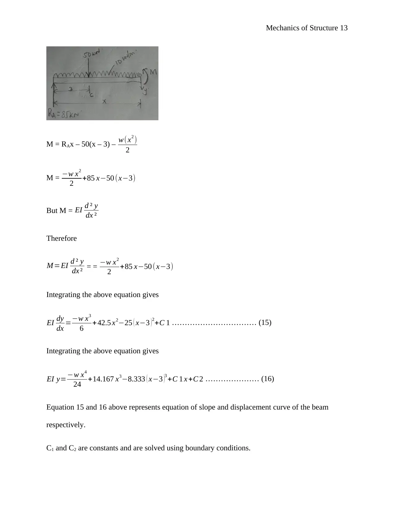
Taking moments at B so as to determine support reactions
∑ MB=0
10RA – (7 x 50) – (10 x 10 x 5) = 0 → 10RA = 850 → RA = 85 kN
RB = 50 + (10 x 10) – 85 = 65 kN
Taking moments at a point x between C and B to the left hand side
⊘ This is a preview!⊘
Do you want full access?
Subscribe today to unlock all pages.

Trusted by 1+ million students worldwide
Mechanics of Structure 13
M = RAx – 50(x – 3) – w( x2 )
2
M = −w x2
2 +85 x−50 (x−3)
But M = EI d ² y
dx ²
Therefore
M =EI d ² y
dx ² = = −w x2
2 +85 x−50 ( x−3)
Integrating the above equation gives
EI dy
dx =−w x3
6 + 42.5 x2−25 ( x−3 )2+C 1 …………………………… (15)
Integrating the above equation gives
EI y=−w x4
24 +14.167 x3−8.333 ( x−3 )3 +C 1 x +C 2 ………………… (16)
Equation 15 and 16 above represents equation of slope and displacement curve of the beam
respectively.
C1 and C2 are constants and are solved using boundary conditions.
Paraphrase This Document
Need a fresh take? Get an instant paraphrase of this document with our AI Paraphraser
Mechanics of Structure 14
The first boundary condition is that deflection is zero at support A, i.e. when x = 0 m, y = 0
The second boundary equation is that deflection is zero at support B, i.e. when x = L = 10, y = 0
Substituting y = 0 when x = 0 in equation 16 gives:
0=0+0+ 225+C 2 → C2 = -225
Substituting y = 0 when x = 10 m in equation 16 gives:
Remember w = 10 kN/m
0=−10 ( 104 )
24 +14.167 ( 10 ) 3−8.333 ( 7 ) 3 +10 C 1−225
0 = -4166.67 + 14167 – 2858.22 + 10C1 – 225
C1 =-691.71
Therefore
Equation for slope, dy
dx = 1
EI [ −w x3
6 + 42.5 x2−25 ( x−3 )2−691.71]
Equation for displacement, y= 1
EI [ −w x4
24 + 14.167 x3 −8.333 ( x −3 )3−691.71 x−225]
EI = 200 GPa x 65 x 106 mm4
EI = 200 GPa x 65 x 106 mm4 = 200 x 103 N/mm2 x 65 x 106 mm4 = 1.3 x 10¹³ Nmm2 = 13,000
kNm2
Slope at A:
Mechanics of Structure 15
At A, x = 0, w = 10 kN/m and EI = 13,000 kNm2; substituting these values in slope equation
gives:
ΔA = 1
13000 [0+ 0−25 (−3 )2 −691.71] = 1
13000 [−225−691.71] = -0.917 radians = 0.917 radians
Slope at B:
At B, x = 10, w = 10 kN/m and EI = 13,000 kNm2; substituting these values in slope equation
gives:
ΔB = 1
13000 [ −10 ( 10 )3
6 + 42.5 (10 )2−25 ( 7 )2−691.71] = 1
13000 [−1666.67+4250−1252−691.71]
= 0.0492 radians
Displacement at C:
At C, x = 3, w = 10 kN/m and EI = 13,000 kNm2; substituting these values in displacement
equation gives
y= 1
13,000 [−10 ( 3 ) 4
24 +14.167 ( 3 ) 3 −0−691.71(3)−225]
y= 1
13,000 [−33.75+382.509−2075.13−225] = -0.15 m = 0.00015 mm
References
Ramasamy, V. R. P., 2012. Strength of materials. New delhi: Perason India.
Selvam, V. & Bindhu, K., 2014. Computation of deflection and slope in beams by using
Maxwell-Betti theorem. Journal of Structural Engineering, 41(3), pp. 279-286.
⊘ This is a preview!⊘
Do you want full access?
Subscribe today to unlock all pages.

Trusted by 1+ million students worldwide
Mechanics of Structure 16
Sigurdardottir, D., Stearns, J. & Glisic, B., 2017. Error in the determination of the deformed
shape of prismatic beam using double integration of curvature. Smart Materials and Structures,
26(7).
Sulaiman, H., Othman, M., Aziz, M. & M.M.F.A., 2015. Theory and applications of applied
electromagnetics: APPEIC 2014. Cham, Switzerland: Springer International Publishing.
The Engineering ToolBox, (n.d.). Area moment of inertia - typical cross sections I. [Online]
Available at: http://www.engineeringtoolbox.com/area-moment-inertia-d_1328.html
[Accessed 25 September 2017].
University of Cambridge, (n.d.). How to discover for yourself the solution of the cubic. [Online]
Available at: https://www.dpmms.cam.ac.uk/~wtg10/cubic.html
[Accessed 25 September 2017].
1 out of 16
Your All-in-One AI-Powered Toolkit for Academic Success.
+13062052269
info@desklib.com
Available 24*7 on WhatsApp / Email
![[object Object]](/_next/static/media/star-bottom.7253800d.svg)
Unlock your academic potential
© 2024 | Zucol Services PVT LTD | All rights reserved.


