Mechanics of Structures 2: Beam Analysis, Stress, and Shear Forces
VerifiedAdded on 2023/06/11
|6
|669
|382
Homework Assignment
AI Summary
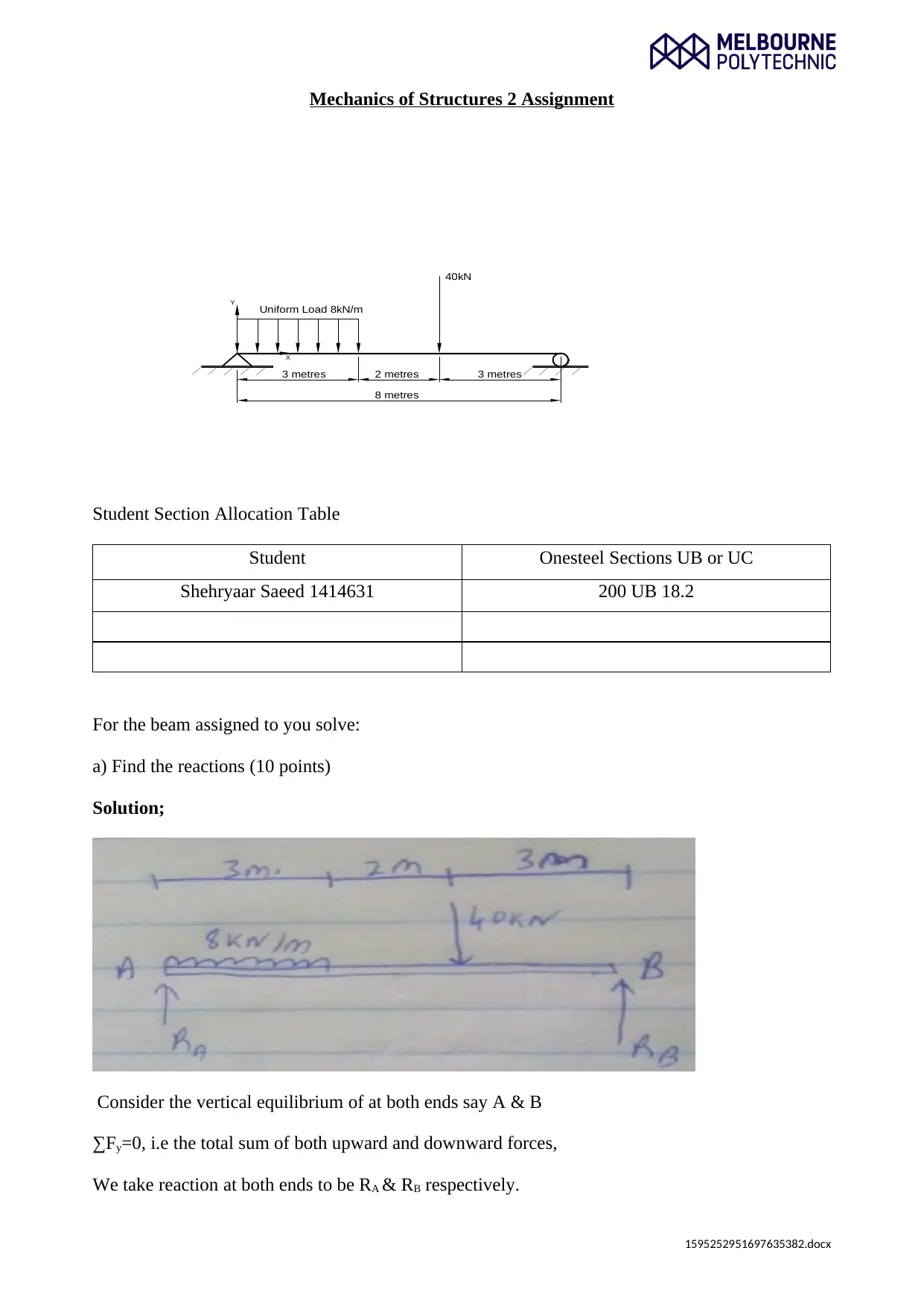
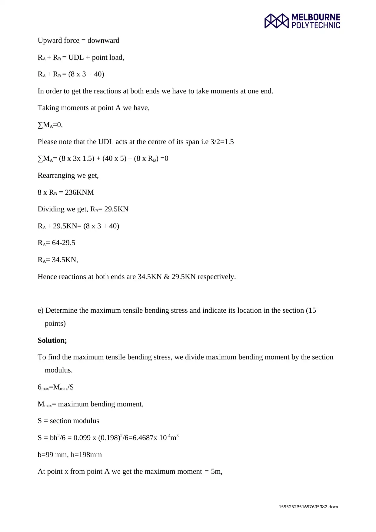
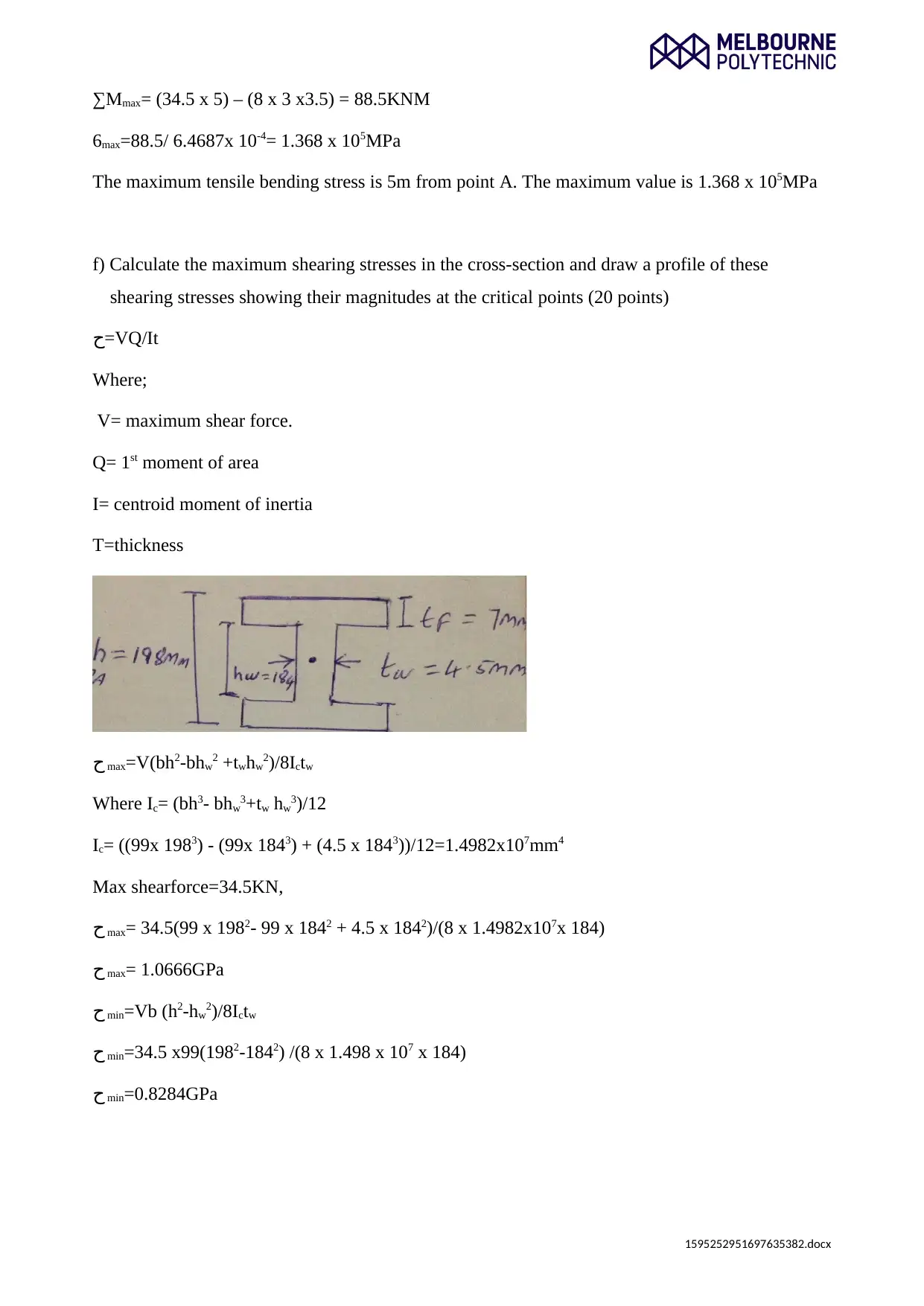
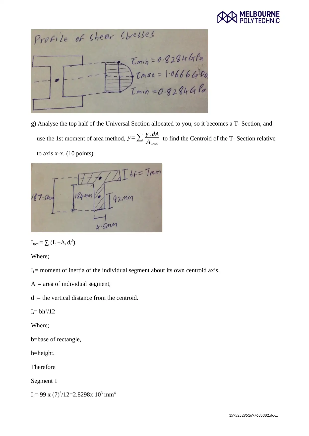
This assignment solution for Mechanics of Structures 2 focuses on analyzing a beam under combined loading conditions. It includes calculating reactions at supports, drawing shear and moment diagrams, determining the moment of inertia, finding maximum tensile bending stress and its location, cal...

Mechanics of Structures 2 Assignment
Y
X
8 metres
3 metres
Uniform Load 8kN/m
2 metres 3 metres
40kN
Student Section Allocation Table
Student Onesteel Sections UB or UC
Shehryaar Saeed 1414631 200 UB 18.2
For the beam assigned to you solve:
a) Find the reactions (10 points)
Solution;
Consider the vertical equilibrium of at both ends say A & B
∑Fy=0, i.e the total sum of both upward and downward forces,
We take reaction at both ends to be RA & RB respectively.
1595252951697635382.docx
Paraphrase This Document
Need a fresh take? Get an instant paraphrase of this document with our AI Paraphraser

Upward force = downward
RA + RB = UDL + point load,
RA + RB = (8 x 3 + 40)
In order to get the reactions at both ends we have to take moments at one end.
Taking moments at point A we have,
∑MA=0,
Please note that the UDL acts at the centre of its span i.e 3/2=1.5
∑MA= (8 x 3x 1.5) + (40 x 5) – (8 x RB) =0
Rearranging we get,
8 x RB = 236KNM
Dividing we get, RB= 29.5KN
RA + 29.5KN= (8 x 3 + 40)
RA= 64-29.5
RA= 34.5KN,
Hence reactions at both ends are 34.5KN & 29.5KN respectively.
e) Determine the maximum tensile bending stress and indicate its location in the section (15
points)
Solution;
To find the maximum tensile bending stress, we divide maximum bending moment by the section
modulus.
6max=Mmax/S
Mmax= maximum bending moment.
S = section modulus
S = bh2/6 = 0.099 x (0.198)2/6=6.4687x 10-4m3
b=99 mm, h=198mm
At point x from point A we get the maximum moment = 5m,
1595252951697635382.docx

∑Mmax= (34.5 x 5) – (8 x 3 x3.5) = 88.5KNM
6max=88.5/ 6.4687x 10-4= 1.368 x 10⁵MPa
The maximum tensile bending stress is 5m from point A. The maximum value is 1.368 x 10⁵MPa
f) Calculate the maximum shearing stresses in the cross-section and draw a profile of these
shearing stresses showing their magnitudes at the critical points (20 points)
ﺡ=VQ/It
Where;
V= maximum shear force.
Q= 1st moment of area
I= centroid moment of inertia
T=thickness
ﺡ max=V(bh2-bhw2 +twhw2)/8Ictw
Where Ic= (bh3- bhw3+tw hw3)/12
Ic= ((99x 1983) - (99x 1843) + (4.5 x 1843))/12=1.4982x107mm4
Max shearforce=34.5KN,
ﺡ max= 34.5(99 x 1982- 99 x 1842 + 4.5 x 1842)/(8 x 1.4982x107x 184)
ﺡ max= 1.0666GPa
ﺡ min=Vb (h2-hw2)/8Ictw
ﺡ min=34.5 x99(1982-1842) /(8 x 1.498 x 107 x 184)
ﺡ min=0.8284GPa
1595252951697635382.docx
⊘ This is a preview!⊘
Do you want full access?
Subscribe today to unlock all pages.

Trusted by 1+ million students worldwide

g) Analyse the top half of the Universal Section allocated to you, so it becomes a T- Section, and
use the 1st moment of area method, y=∑ y . dA
ATotal
to find the Centroid of the T- Section relative
to axis x-x. (10 points)
Itotal= ∑ (Ii +Ai di2)
Where;
Ii = moment of inertia of the individual segment about its own centroid axis.
Ai = area of individual segment,
d i= the vertical distance from the centroid.
Ii= bh3/12
Where;
b=base of rectangle,
h=height.
Therefore
Segment 1
I1= 99 x (7)3/12=2.8298x 103 mm4
1595252951697635382.docx
Paraphrase This Document
Need a fresh take? Get an instant paraphrase of this document with our AI Paraphraser

A1= 99 x 7= 693mm2
d1= 184+ 7/2 = 187.5mm
Segment 2
I2= 4.5x (184)3/12=2.336 x 106mm4
A2= 184 x 4.5= 828mm2
d2 = 184/2 =92mm
Reference
1595252951697635382.docx
d1= 184+ 7/2 = 187.5mm
Segment 2
I2= 4.5x (184)3/12=2.336 x 106mm4
A2= 184 x 4.5= 828mm2
d2 = 184/2 =92mm
Reference
1595252951697635382.docx

Majid, T. A. (2014). Theory of Structures. Penerbit USM. Available from:
http://www.myilibrary.com?id=678949. (Date of Access: 7th May 2018).
Spofford, C. M. (2013). The theory of structures.
1595252951697635382.docx
http://www.myilibrary.com?id=678949. (Date of Access: 7th May 2018).
Spofford, C. M. (2013). The theory of structures.
1595252951697635382.docx
⊘ This is a preview!⊘
Do you want full access?
Subscribe today to unlock all pages.

Trusted by 1+ million students worldwide
1 out of 6

Your All-in-One AI-Powered Toolkit for Academic Success.
+13062052269
info@desklib.com
Available 24*7 on WhatsApp / Email
Unlock your academic potential
© 2024 | Zucol Services PVT LTD | All rights reserved.