Mechatronic Design Project: Industry 4.0 and Shaft Design
VerifiedAdded on 2022/09/18
|16
|1326
|47
Project
AI Summary
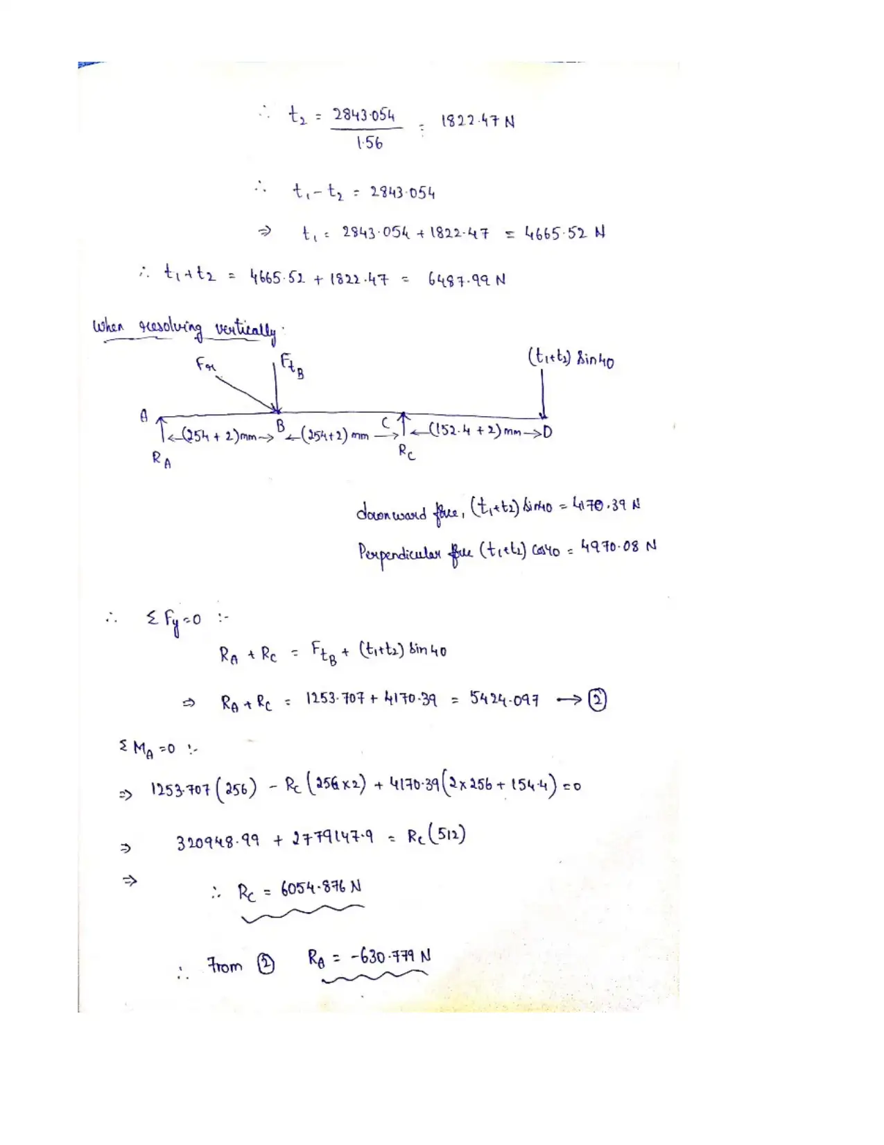
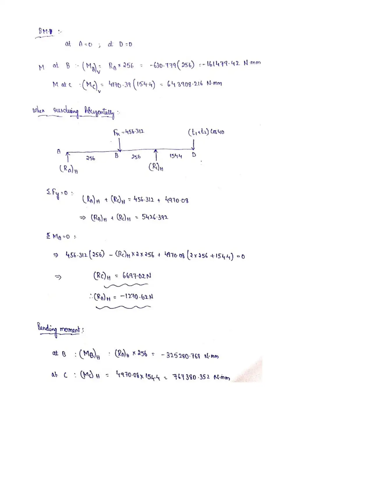
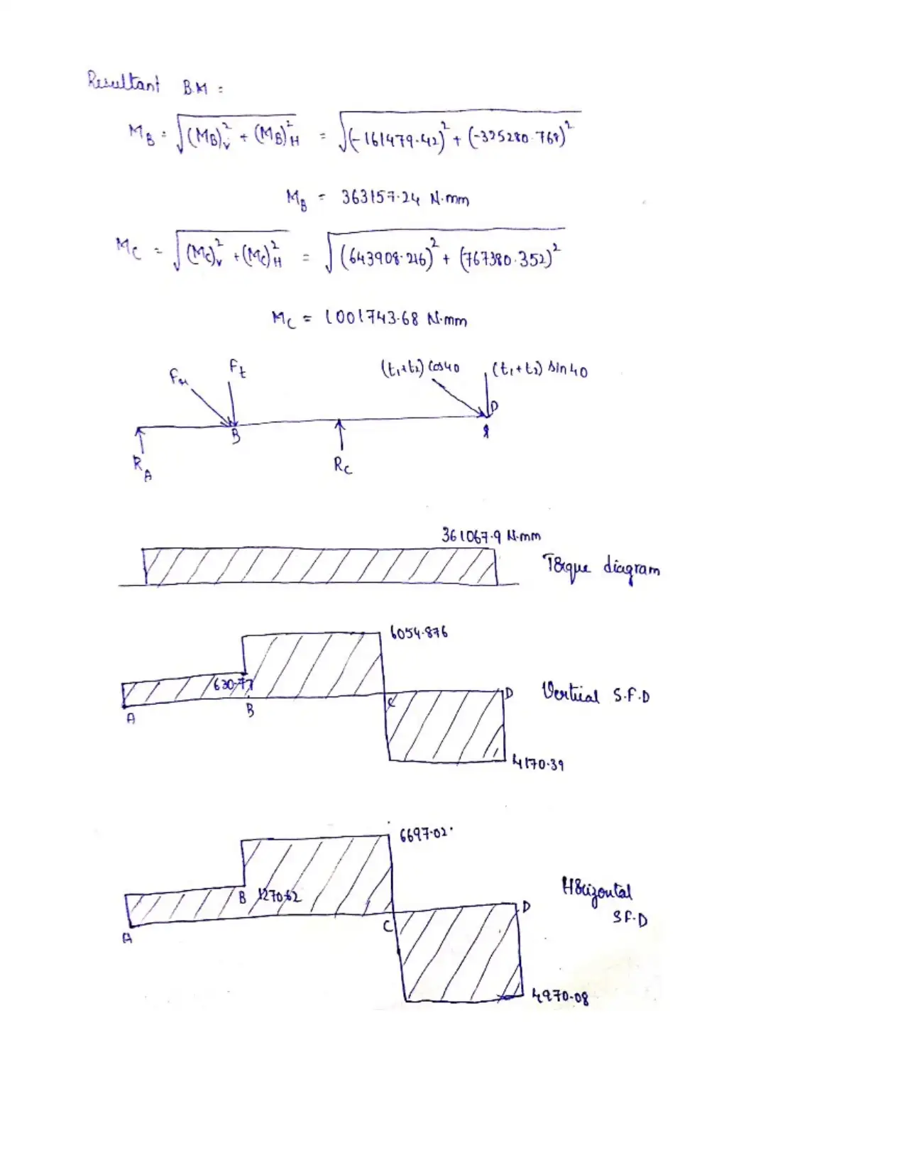
This mechatronic design project addresses several key areas within mechanical engineering and the context of Industry 4.0. The assignment begins with an essay exploring the relationship between mechatronic design and the trends in manufacturing, specifically Industry 4.0, discussing the definition of mechatronic design, Industry 4.0, the contribution of mechatronic design to Industry 4.0 and future of mechanical and mechatronic engineering. The project then proceeds with a detailed analysis of rotating shafts, including force and stress analysis, material selection, and design considerations for various load conditions. The assignment requires the student to specify suitable materials for the shaft, perform force analysis, stress analysis, and determine shaft geometry while considering design factors. The project also includes gear and power transmission system analysis. The final part of the project involves a detailed design of a drive system used in a coal crushing and conveying system, including force analysis, torque, shear, and bending moment diagrams, and shaft diameter calculations. The project encompasses multiple aspects of mechanical design, material selection, and engineering analysis in the context of real-world applications.

1 out of 16
Related Documents


Your All-in-One AI-Powered Toolkit for Academic Success.
+13062052269
info@desklib.com
Available 24*7 on WhatsApp / Email
![[object Object]](/_next/static/media/star-bottom.7253800d.svg)
Copyright © 2020–2026 A2Z Services. All Rights Reserved. Developed and managed by ZUCOL.