Mechatronics Components: Arduino Uno, 12c LCD Display, RAMPS 1.4
VerifiedAdded on 2023/04/21
|10
|2354
|82
AI Summary
This research paper describes the mechatronic components of Arduino Uno, 12c LCD Display, and RAMPS 1.4. It explains their operation and their role in mechatronic systems.
Contribute Materials
Your contribution can guide someone’s learning journey. Share your
documents today.
Mechatronics 1
MECHATRONICS COMPONENTS
By Name
Course
Instructor
Institution
Location
Date
MECHATRONICS COMPONENTS
By Name
Course
Instructor
Institution
Location
Date
Secure Best Marks with AI Grader
Need help grading? Try our AI Grader for instant feedback on your assignments.
Mechatronics 2
INTRODUCTION
This research paper seeks to describe the following mechatronic components, namely, Arduino
Uno, 12c LCD display, RAMPS 1.4, Arduino Mega 2560 board, 12864 LCD Controller, Power
Supply 12V, Connect Motors, Thermistors, E3D v6 Hotend and Heatbed, Fan, and steeper motor
by analyzing how they operate.
Arduino Uno
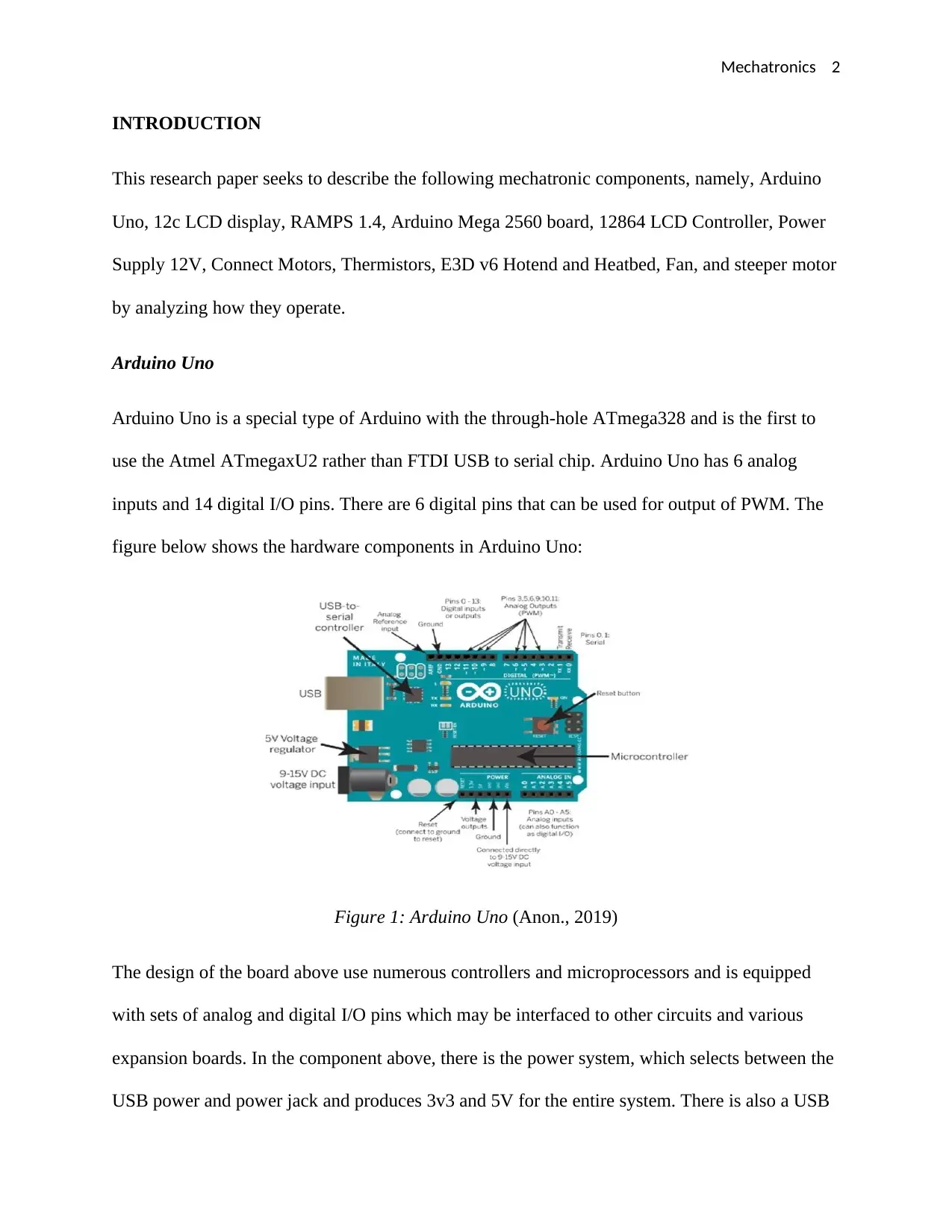
Arduino Uno is a special type of Arduino with the through-hole ATmega328 and is the first to
use the Atmel ATmegaxU2 rather than FTDI USB to serial chip. Arduino Uno has 6 analog
inputs and 14 digital I/O pins. There are 6 digital pins that can be used for output of PWM. The
figure below shows the hardware components in Arduino Uno:
Figure 1: Arduino Uno (Anon., 2019)
The design of the board above use numerous controllers and microprocessors and is equipped
with sets of analog and digital I/O pins which may be interfaced to other circuits and various
expansion boards. In the component above, there is the power system, which selects between the
USB power and power jack and produces 3v3 and 5V for the entire system. There is also a USB
INTRODUCTION
This research paper seeks to describe the following mechatronic components, namely, Arduino
Uno, 12c LCD display, RAMPS 1.4, Arduino Mega 2560 board, 12864 LCD Controller, Power
Supply 12V, Connect Motors, Thermistors, E3D v6 Hotend and Heatbed, Fan, and steeper motor
by analyzing how they operate.
Arduino Uno
Arduino Uno is a special type of Arduino with the through-hole ATmega328 and is the first to
use the Atmel ATmegaxU2 rather than FTDI USB to serial chip. Arduino Uno has 6 analog
inputs and 14 digital I/O pins. There are 6 digital pins that can be used for output of PWM. The
figure below shows the hardware components in Arduino Uno:
Figure 1: Arduino Uno (Anon., 2019)
The design of the board above use numerous controllers and microprocessors and is equipped
with sets of analog and digital I/O pins which may be interfaced to other circuits and various
expansion boards. In the component above, there is the power system, which selects between the
USB power and power jack and produces 3v3 and 5V for the entire system. There is also a USB
Mechatronics 3
to serial controller which contains the bootloader that is used in loading programs into the
ATMEGA328P (Anon., 2019).
Power System
In case the power supply is connected to the power jack, then the supplied power will be between
15V and 9V. The two chips are the voltage regulators that generates 5V supply.
The Vin is connected directly to the power supply. LM385D chip is connected to the Vin, the
chip which contains two operational amplifiers. One of the op-amps is not used at all and the
other one is used as a comparator. Vin/2 is compared to 3V3 and if 3V3 is less than Vin/2, then
the output is 5V and that is used in turning off the supply from the USB.
USB Controller
This component of Arduino Uno is used in loading the code into ATMEGA328P and is
implemented with ATMEGA8U2-MU. The main controller is the ATMEGA328P and this is
where the written code is executed and is connected directly to the I/O pins.
12C LCD Display
The integration of an LCD display enables interactivity of the developed project, permitting the
operator to read directly the parameters of the output. These values can either be numerical
values or simple text read by sensors, such as number of cycles that the Arduino is performing,
pressure or even temperature.
Mechatronics 4
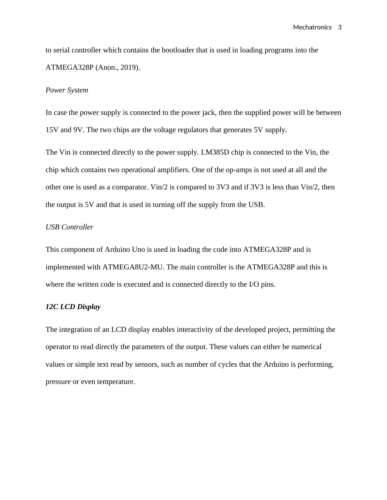
Figure 2: 12C LCD Display (Yao-qiang, et al., 2013)
When 12C LCD Display is connected to the microcontroller like Arduino Uno, these displays
needs numerous connection pins virtually practically occupying almost all I/O available and
leaving the microprocessor few outputs for any other sensors and devices. The 12C LCD Display
has an integrated microchip that control this type of communication, and then all of the output
and input information are restricted to only two pins. This type of display uses two bidirectional
lines, known as Serial Clock Line and Serial Data Line and all must be connected through
pulled-up resistors. This device has a 12C address that it uses when sending messages or
accepting commands. In case of Arduino Uno, this address is usually 0x27 (Yao-qiang, et al.,
2013).
RAMPS 1.4
Reprap Arduino mega pololu shield, RAMPS 1.4 is majorly designed for the purposes of using
pololu steeper driven board. Ramps 1.4 can only work when connected to its mother board
4988/DRV8825 and Mega 2560. RAMPS 1.4 is composed of a max of five Pololu Stepper
drivers, an Arduino Mega 2560 board, and a RAMPS 1.4 shield and it can control up to 5 stepper
Secure Best Marks with AI Grader
Need help grading? Try our AI Grader for instant feedback on your assignments.
Mechatronics 5
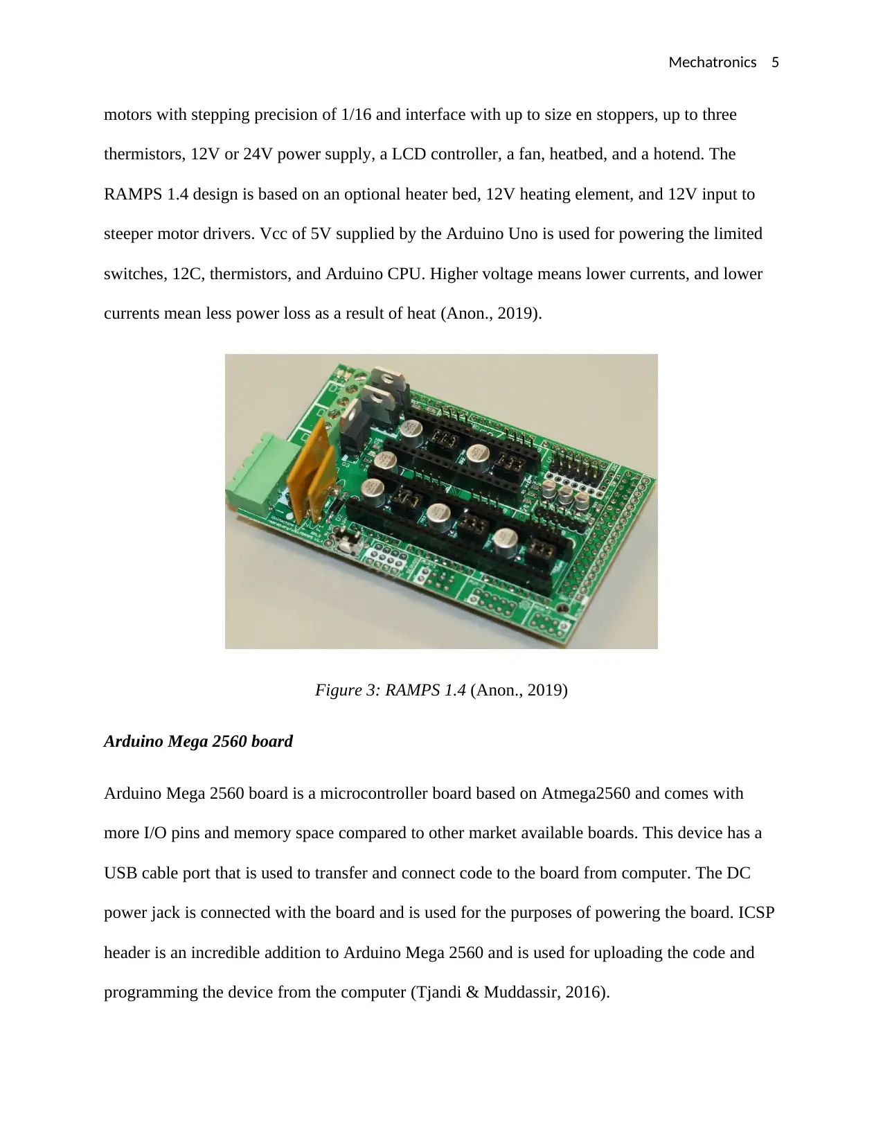
motors with stepping precision of 1/16 and interface with up to size en stoppers, up to three
thermistors, 12V or 24V power supply, a LCD controller, a fan, heatbed, and a hotend. The
RAMPS 1.4 design is based on an optional heater bed, 12V heating element, and 12V input to
steeper motor drivers. Vcc of 5V supplied by the Arduino Uno is used for powering the limited
switches, 12C, thermistors, and Arduino CPU. Higher voltage means lower currents, and lower
currents mean less power loss as a result of heat (Anon., 2019).
Figure 3: RAMPS 1.4 (Anon., 2019)
Arduino Mega 2560 board
Arduino Mega 2560 board is a microcontroller board based on Atmega2560 and comes with
more I/O pins and memory space compared to other market available boards. This device has a
USB cable port that is used to transfer and connect code to the board from computer. The DC
power jack is connected with the board and is used for the purposes of powering the board. ICSP
header is an incredible addition to Arduino Mega 2560 and is used for uploading the code and
programming the device from the computer (Tjandi & Muddassir, 2016).
Mechatronics 6
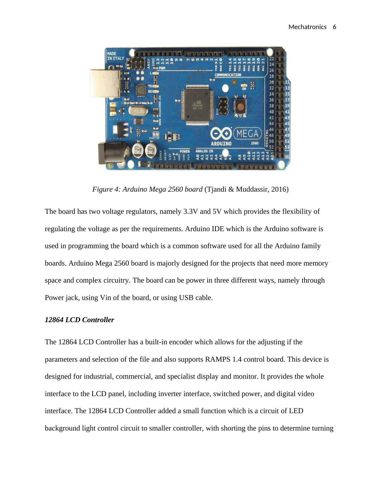
Figure 4: Arduino Mega 2560 board (Tjandi & Muddassir, 2016)
The board has two voltage regulators, namely 3.3V and 5V which provides the flexibility of
regulating the voltage as per the requirements. Arduino IDE which is the Arduino software is
used in programming the board which is a common software used for all the Arduino family
boards. Arduino Mega 2560 board is majorly designed for the projects that need more memory
space and complex circuitry. The board can be power in three different ways, namely through
Power jack, using Vin of the board, or using USB cable.
12864 LCD Controller
The 12864 LCD Controller has a built-in encoder which allows for the adjusting if the
parameters and selection of the file and also supports RAMPS 1.4 control board. This device is
designed for industrial, commercial, and specialist display and monitor. It provides the whole
interface to the LCD panel, including inverter interface, switched power, and digital video
interface. The 12864 LCD Controller added a small function which is a circuit of LED
background light control circuit to smaller controller, with shorting the pins to determine turning
Mechatronics 7
on 30 seconds or turning on all the time and then automatically turning off. Thie device is
composed of an LCD glass and LCD Controller. In the LCD Glass there are numerous small
units, one unit is made up of two polarizers, between which liquid crystals are present, between
which there are two electrodes (Choi & Tae-Il, 2010).
An LCD controller regulates alternating voltage across the two electrodes such that the average
is zero to prevent permanent crystal alignment. The subsystem of LCD runs on a clock known as
frame clock. When the RMS voltage across the electrodes is less than the threshold of lighting,
then there is glowing of LCD lighting.
Power Supply 12V
A 12V power supply is performs numerous tasks, namely, ensuring that the outout volate is kept
at constant level, prevent any AC from appearing at the output of supply, produces a DC supply
from the mains supply sine wave, and changes the level of supply to a 12V which is appropriate
for driving the load circuit. The primary function of the power supply is to convert the 12V
electrical power to the type the circuit of computer can use. The power supply is designed to
convert 230V 50Hz AC nominal or 115V 60Hz AC into 12V DC power. 12V power supply
delivers a steady and good DC power supply to enable proper operation of the system. The main
purpose of 12V power supply is to run disk drive motors and also voltage regulators of higher-
output processor in some of the boards (Knorr, et al., 2010).
Connect Motors
Connect motors are normally fitted in smaller electrical devices like power tools and they
automatically start turning when electricity is connected to the motors. Motors converts electrical
energy into mechanical energy, hence the direction of flow of current periodically changes.
Paraphrase This Document
Need a fresh take? Get an instant paraphrase of this document with our AI Paraphraser
Mechatronics 8
Motors have two primary components, namely, rotor and stator. The rotor is the rotating
electrical part of the AC motor while the stator is the stationary electrical part and is composed
of numerous electromagnet arranged to form a hollow cylinder. By progressively changing the
polarity of the stator pole such that there magnetic field combined rotates, then the rotor will
follow and rotate with the stator magnetic field (Li & Zhen, 2013).
Thermistor
This is a type of resistor whose resistance depends on the temperature and is used widely self-
resetting heating element, temperature sensors, and inrush current limiters. In positive
temperature coefficient type, the resistance increases with rise in temperature and are installed
commonly in series with the circuit to protect against the conditions of overcurrent. In negative
temperature coefficient type, the resistance deceases with rise in temperature and are used as
temperature sensors (Ling & Lin, 2013).
E3D v6 Hotend and Heatbed
E3D v6 is a high temperature Hotend with the ability of attaining a wide temperature ranges. The
temperature which ignites some plastics are within ordinary printing temperature of other
plastics. E3D v6 Hotend and Heatbed is one of the most known and most significant third-party
upgrades that 3D printing fan can make to their printers. The pervasive nature of the J-head
mount makes it compatible with majority of the open standard RepRap printers, and the
functional design assist in the prevention of hotend maladies which include variable heatsink
cooling airflow, inconsistent nozzle heating, and heat creep (Anon., 2019).
Fan
Mechatronics 9
A fan is a mechanical device used for mobbing air in a direction at an angle to the incoming air.
Fans such as centrifugal fan normally contain a ducted housing to direct air going out in a
specific direction. Fans use the kinetic energy of the impellers to increase the air stream volume
which in turn moves against drag caused by ducts. Fans as constant-volume or constant-
displacement devices such that at a constant speed, a fan moves relatively constant air volume
and not constant mass (Xu & Wensi, 2012).
Stepper motor
A stepper motor is an electromechanical device that converts power into mechanical power from
electrical power. Stepper motor uses the principle of operation of magnet to make the shaft turn
at a precise distance when an electric pulse is applied. The stepper motor steps denotes discrete
angular movements which takes place in a sequential manner and are equivalent in displacement,
when correctly functioning the number of steps performed must be equivalent to the control
pulses applied to the motor phase. The speed of this device can be regulated in a wide range of
values by varying the frequency of input impulses (Pawliczek & Soppa, 2017).
Mechatronics 10
BIBLIOGRAPHY
Anon., 2019. Arduino - ArduinoUno. s.l.:Arduino.cc. : https://www.arduino.cc/en/Guide/ArduinoUno
Anon., 2019. How To: Successfully Assemble an E3D v6 All-Metal HotEnd | MatterHackers.
s.l.:MatterHackers. ttps://www.matterhackers.com/articles/how-to-assemble-an-e3d-v6-all-metal-
hotend
Anon., 2019. RAMPS 1.4 Arduino Shield | For Pololu and Prusa 3D Printers. s.l.:DIYElectronics.
https://www.diyelectronics.co.za/store/controller-boards/91-ramps-14-arduino-shield.html
Choi, K.-Y. & Tae-Il, O., 2010. A Study on the Controller Design of Cooling System for LCD Panel Console.
s.l.:Journal of the Korea Academia-Industrial cooperation Society. Vol 11. pp. 3666-3672.
Indriani, A. & Witanto, H., 2016. Error of Assembly Microcontroller Arduino Mega and ATmega in the
Control of Temperature for Heating and Cooling System. s.l.:Applied Mechanics and Materials. Vol 842.
pp. 324-328.
Knorr, R., Gilch, M. & Wieser, C., 2010. Stabilization of the 12V onboard power supply. s.l.:ATZelektronik
worldwide. Vol 5. pp. 40-44.
Li, B. & Zhen, Y., 2013. Researching of Speed Regulation System for AC Permanent Magnet Synchronous
Motor. s.l.:Applied Mechanics and Materials. Vo 303. pp. 1204-1208.
Ling, Z.-Y. & Lin, H., 2013. Thick-Film Negative-Temperature-Coefficient Thermistors with a Linear
Resistance-Temperature Relation. s.l.:Chinese Physics Letters. Vol 30. pp 107201.
Pawliczek, R. & Soppa, P., 2017. Measurement and Control System for Analysis of the Operation of the
Stepper Motor. s.l.:Solid State Phenomena. Vol 260. pp. 113-126.
Tjandi, Y. & Muddassir, H., 2016. Monitoring And Device Electrical Control Equipment Based on Arduino
Mega. s.l.:IOSR Journal of Electrical and Electronics Engineering. Vol 11. pp. 101-108.
Xu, Z. & Wensi, D., 2012. Analysis of Internal Flow Field for Centrifugal Fan in Series. s.l.:Applied
Mechanics and Materials. Vol 233. pp. 96-99.
Yao-qiang, L., Tie-jun, X. & Qin-zheng, L., 2013. Design and implementation of LCD controller based on
Avalon-MM burst transfer. s.l.:Journal of Computer Applications. Vol 32. pp. 1467-1469.
1 out of 10
Related Documents


Your All-in-One AI-Powered Toolkit for Academic Success.
+13062052269
info@desklib.com
Available 24*7 on WhatsApp / Email
![[object Object]](/_next/static/media/star-bottom.7253800d.svg)
Unlock your academic potential
© 2024 | Zucol Services PVT LTD | All rights reserved.