logo

Hydraulic and Pneumatic Systems Lab


Added on  2022-08-27

9 Pages366 Words14 Views
 | 
 | 
 | 
MET230L Hydraulic and Pneumatic Systems Lab
Instructor: Calvin Cox
Unit 5 – Course Project Part 3
Hydraulic and Pneumatic Systems Lab_1

Part 3: Circuit Second Modification
Remember to open a new Word file named MET230_Project_Pt3_LastName_FirstName.doc(x).
In this last phase of the project, you will redesign the circuit to meet desired requirements.
a. Open the Project_Pt2_LastName_FirstName simulation file you created in part 2 of this
project.
b. Rename and save it as Project_Pt3_LastName_FirstName
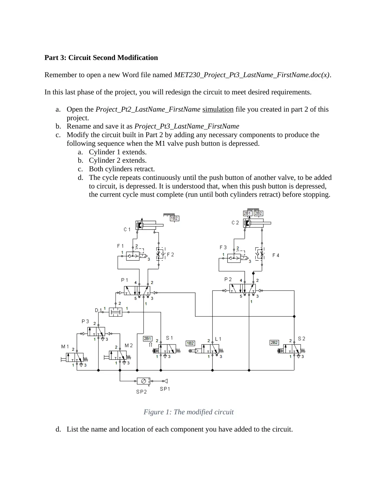
c. Modify the circuit built in Part 2 by adding any necessary components to produce the
following sequence when the M1 valve push button is depressed.
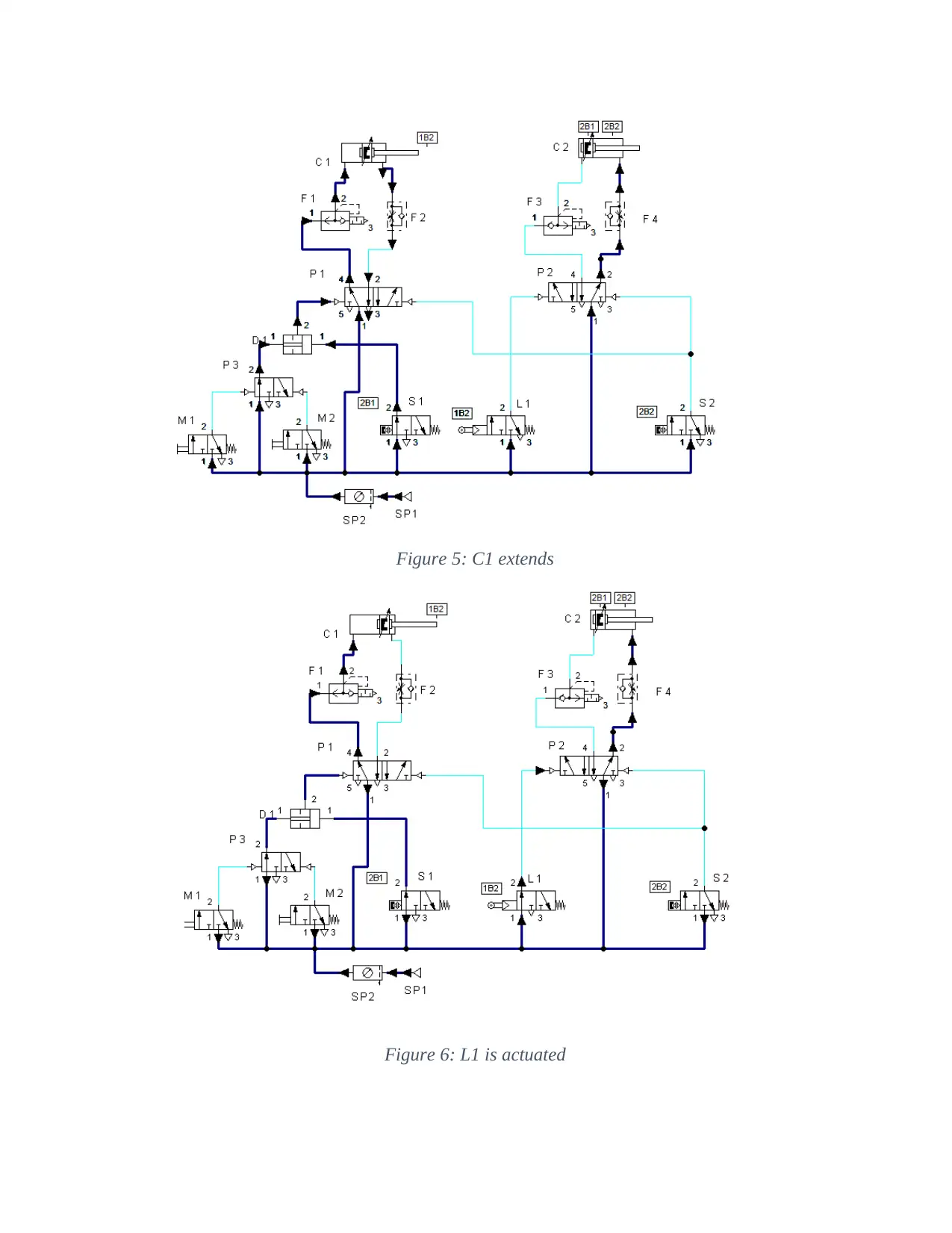
a. Cylinder 1 extends.
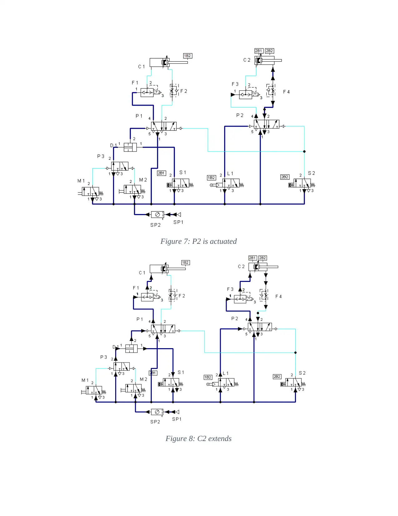
b. Cylinder 2 extends.
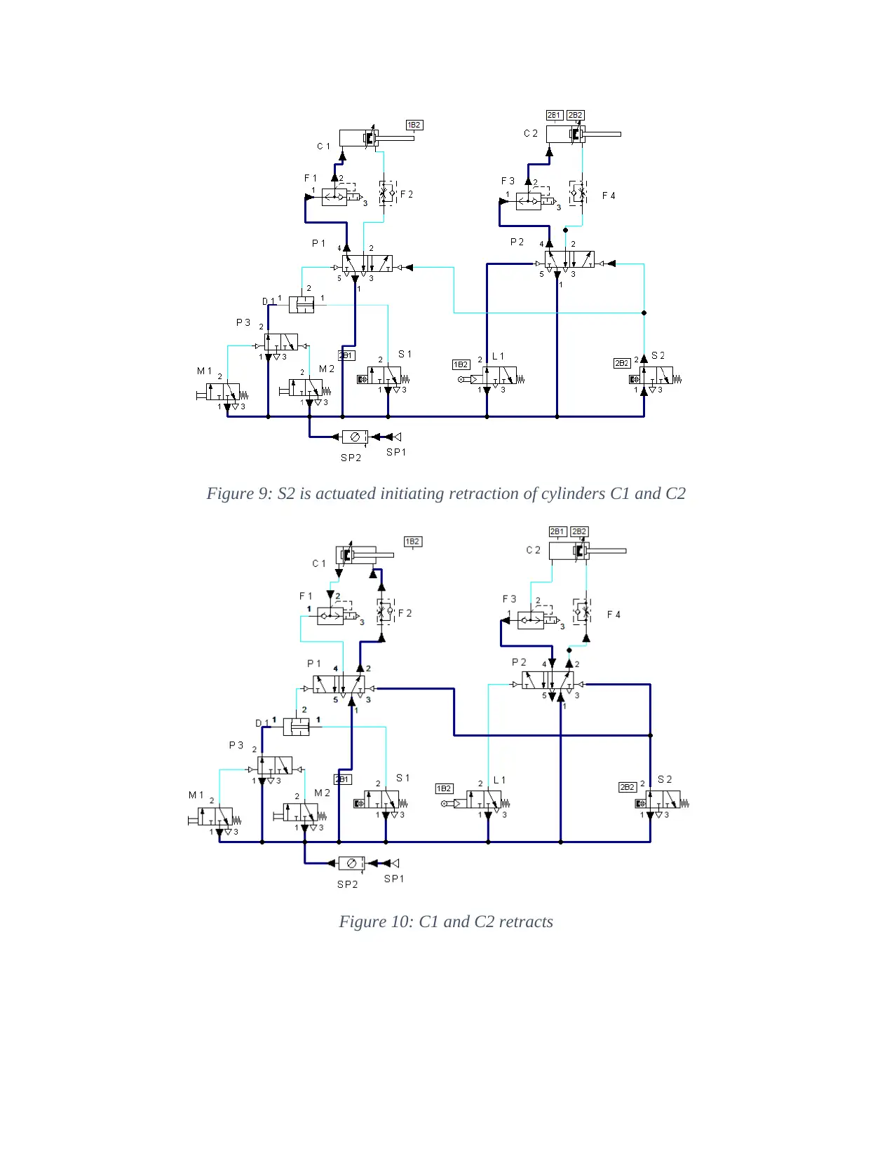
c. Both cylinders retract.
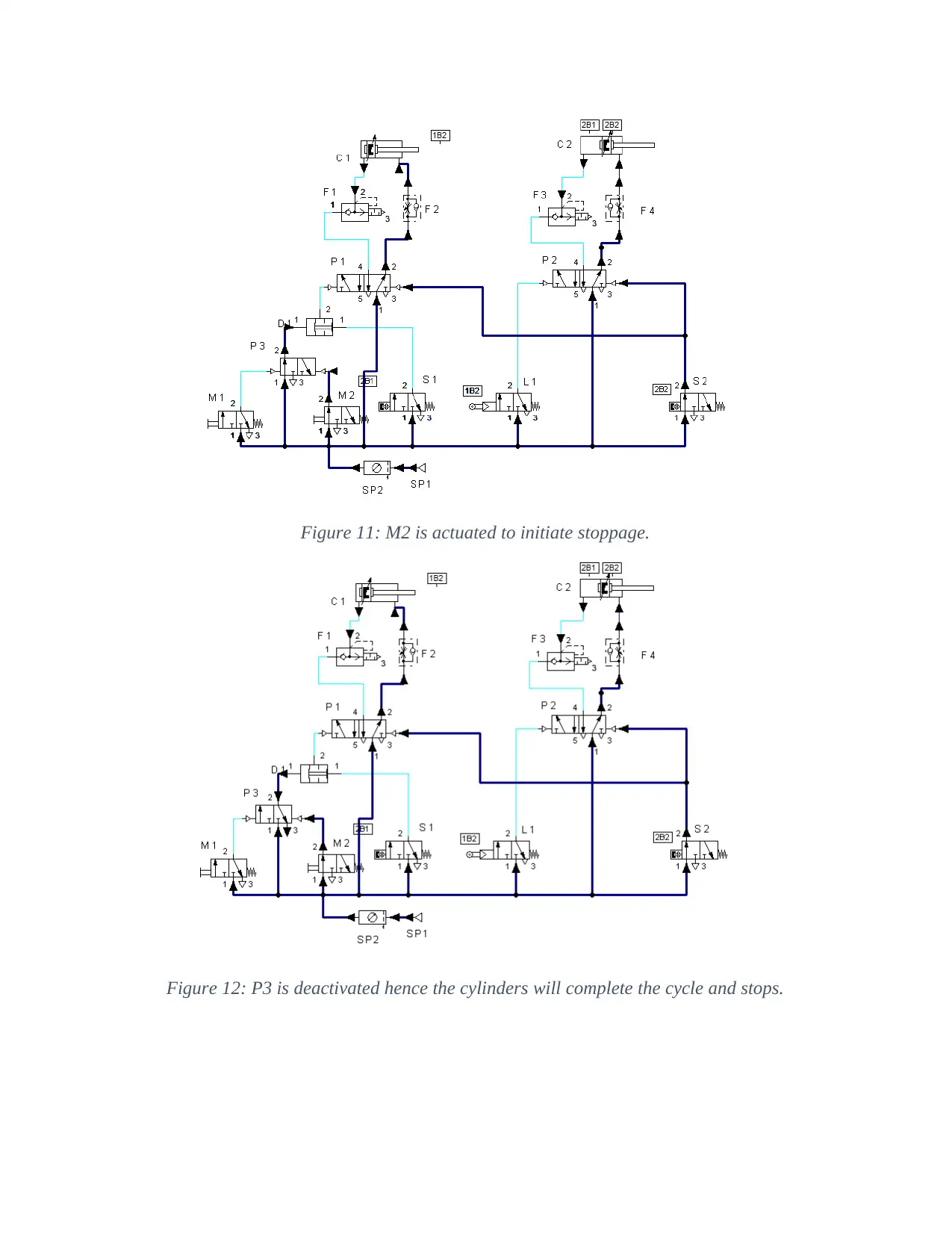
d. The cycle repeats continuously until the push button of another valve, to be added
to circuit, is depressed. It is understood that, when this push button is depressed,
the current cycle must complete (run until both cylinders retract) before stopping.
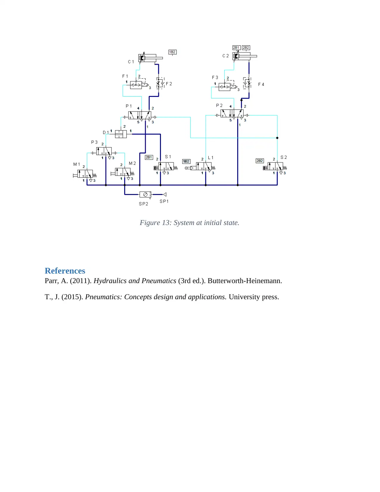
Figure 1: The modified circuit
d. List the name and location of each component you have added to the circuit.
Hydraulic and Pneumatic Systems Lab_2

M2-3/2-way valve with pushbutton placed between air supply unit and P3
P3-3/2-way valve, pneumatically operated located between M1/M2 and D2.
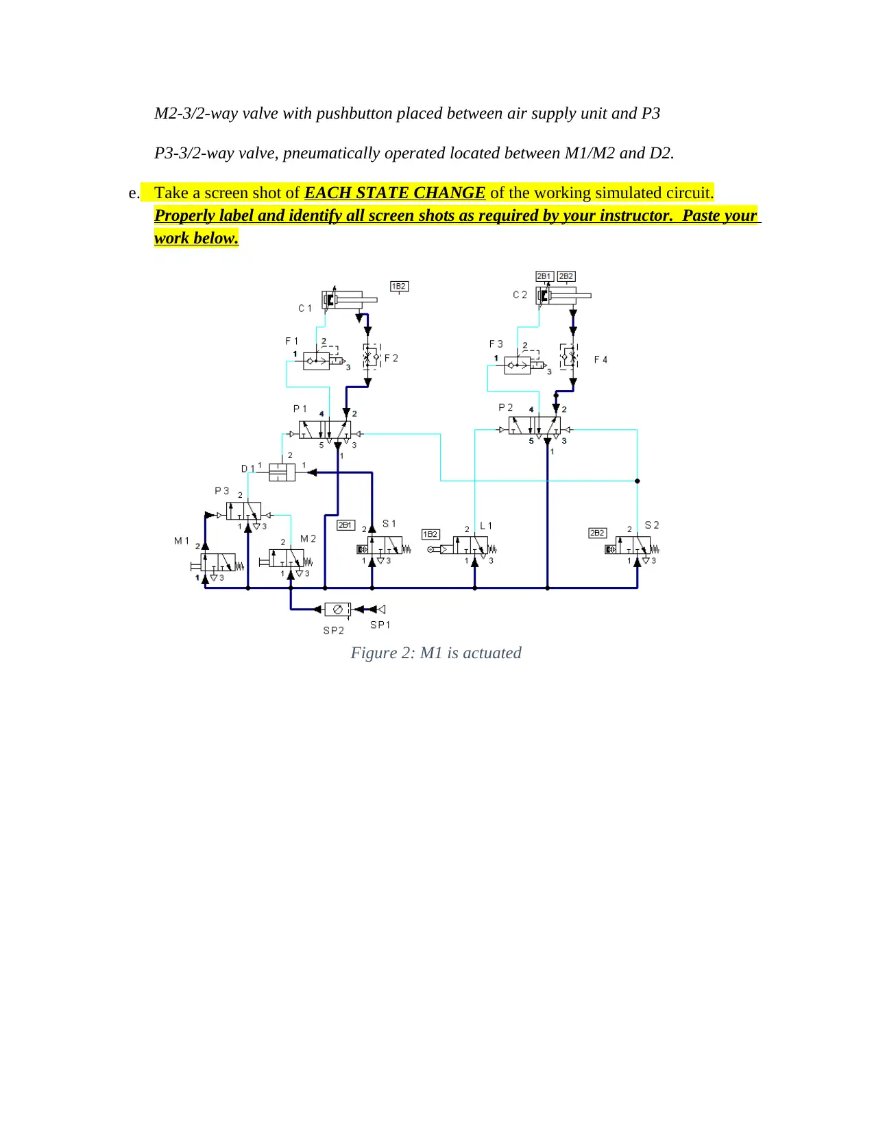
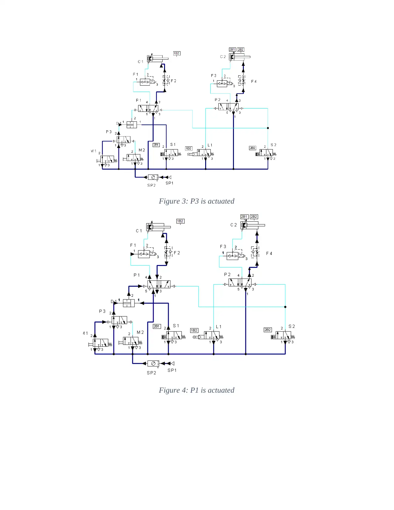
e. Take a screen shot of EACH STATE CHANGE of the working simulated circuit.
Properly label and identify all screen shots as required by your instructor. Paste your
work below.
Figure 2: M1 is actuated
Hydraulic and Pneumatic Systems Lab_3

End of preview

Want to access all the pages? Upload your documents or become a member.

Related Documents