MET230L: Hydraulics and Pneumatics Lab
VerifiedAdded on 2022/12/14
|18
|2077
|139
AI Summary
This document is a lab assignment for MET230L, a course on hydraulics and pneumatics. It covers topics such as time delay valves, interconnection between cylinders, and electro-pneumatic circuits. The document includes circuit diagrams, simulation instructions, and explanations of the working principles.
Contribute Materials
Your contribution can guide someone’s learning journey. Share your
documents today.
MET230L: Hydraulics and Pneumatics Lab
Unit 3 Lab Assignment
Remember to open a new Word file named MET230L_Unit3_Lab_LastName_FirstName.doc(x) if you
have not done so yet.
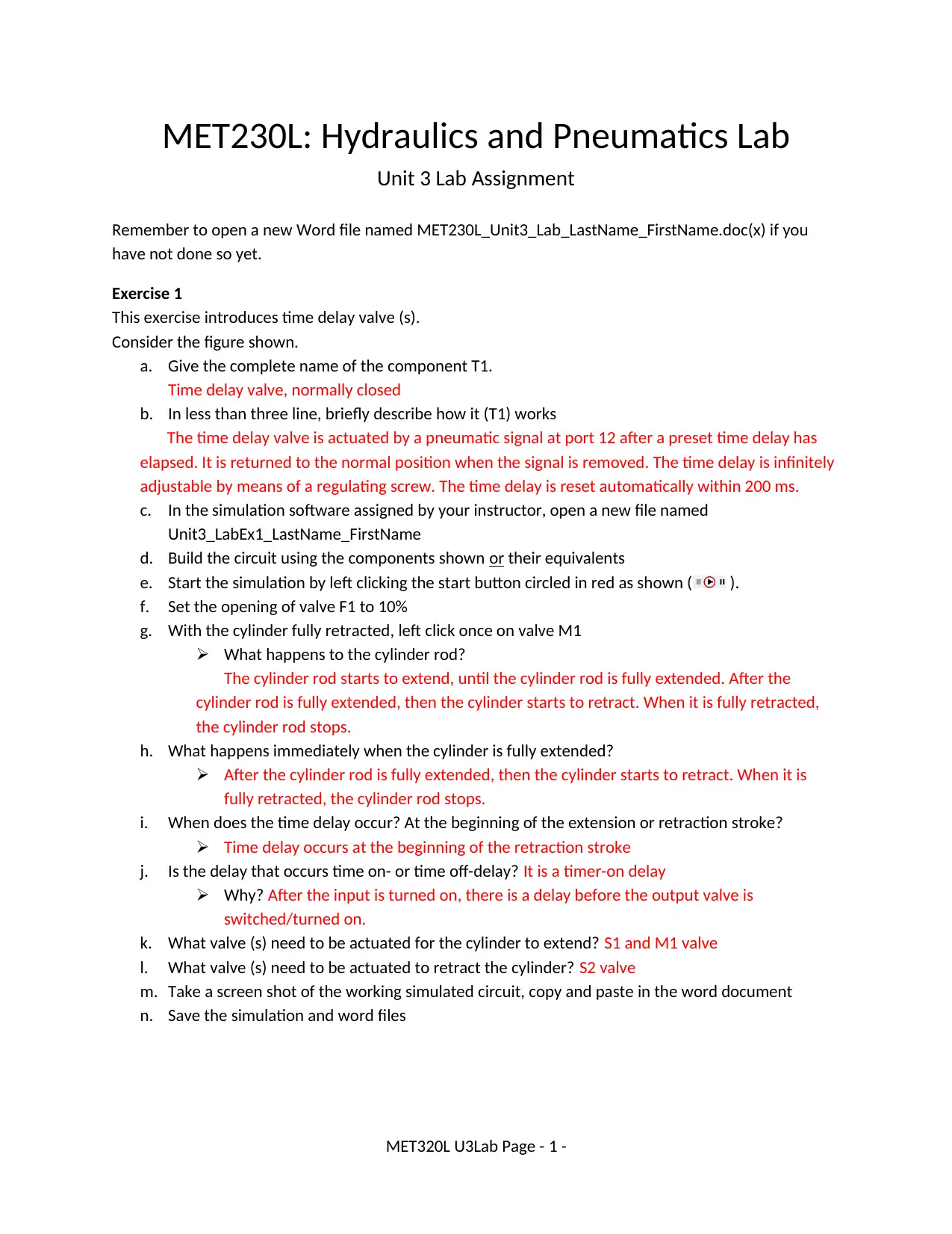
Exercise 1
This exercise introduces time delay valve (s).
Consider the figure shown.
a. Give the complete name of the component T1.
Time delay valve, normally closed
b. In less than three line, briefly describe how it (T1) works
The time delay valve is actuated by a pneumatic signal at port 12 after a preset time delay has
elapsed. It is returned to the normal position when the signal is removed. The time delay is infinitely
adjustable by means of a regulating screw. The time delay is reset automatically within 200 ms.
c. In the simulation software assigned by your instructor, open a new file named
Unit3_LabEx1_LastName_FirstName
d. Build the circuit using the components shown or their equivalents
e. Start the simulation by left clicking the start button circled in red as shown ( ).
f. Set the opening of valve F1 to 10%
g. With the cylinder fully retracted, left click once on valve M1
What happens to the cylinder rod?
The cylinder rod starts to extend, until the cylinder rod is fully extended. After the
cylinder rod is fully extended, then the cylinder starts to retract. When it is fully retracted,
the cylinder rod stops.
h. What happens immediately when the cylinder is fully extended?
After the cylinder rod is fully extended, then the cylinder starts to retract. When it is
fully retracted, the cylinder rod stops.
i. When does the time delay occur? At the beginning of the extension or retraction stroke?
Time delay occurs at the beginning of the retraction stroke
j. Is the delay that occurs time on- or time off-delay? It is a timer-on delay
Why? After the input is turned on, there is a delay before the output valve is
switched/turned on.
k. What valve (s) need to be actuated for the cylinder to extend? S1 and M1 valve
l. What valve (s) need to be actuated to retract the cylinder? S2 valve
m. Take a screen shot of the working simulated circuit, copy and paste in the word document
n. Save the simulation and word files
MET320L U3Lab Page - 1 -
Unit 3 Lab Assignment
Remember to open a new Word file named MET230L_Unit3_Lab_LastName_FirstName.doc(x) if you
have not done so yet.
Exercise 1
This exercise introduces time delay valve (s).
Consider the figure shown.
a. Give the complete name of the component T1.
Time delay valve, normally closed
b. In less than three line, briefly describe how it (T1) works
The time delay valve is actuated by a pneumatic signal at port 12 after a preset time delay has
elapsed. It is returned to the normal position when the signal is removed. The time delay is infinitely
adjustable by means of a regulating screw. The time delay is reset automatically within 200 ms.
c. In the simulation software assigned by your instructor, open a new file named
Unit3_LabEx1_LastName_FirstName
d. Build the circuit using the components shown or their equivalents
e. Start the simulation by left clicking the start button circled in red as shown ( ).
f. Set the opening of valve F1 to 10%
g. With the cylinder fully retracted, left click once on valve M1
What happens to the cylinder rod?
The cylinder rod starts to extend, until the cylinder rod is fully extended. After the
cylinder rod is fully extended, then the cylinder starts to retract. When it is fully retracted,
the cylinder rod stops.
h. What happens immediately when the cylinder is fully extended?
After the cylinder rod is fully extended, then the cylinder starts to retract. When it is
fully retracted, the cylinder rod stops.
i. When does the time delay occur? At the beginning of the extension or retraction stroke?
Time delay occurs at the beginning of the retraction stroke
j. Is the delay that occurs time on- or time off-delay? It is a timer-on delay
Why? After the input is turned on, there is a delay before the output valve is
switched/turned on.
k. What valve (s) need to be actuated for the cylinder to extend? S1 and M1 valve
l. What valve (s) need to be actuated to retract the cylinder? S2 valve
m. Take a screen shot of the working simulated circuit, copy and paste in the word document
n. Save the simulation and word files
MET320L U3Lab Page - 1 -
Secure Best Marks with AI Grader
Need help grading? Try our AI Grader for instant feedback on your assignments.
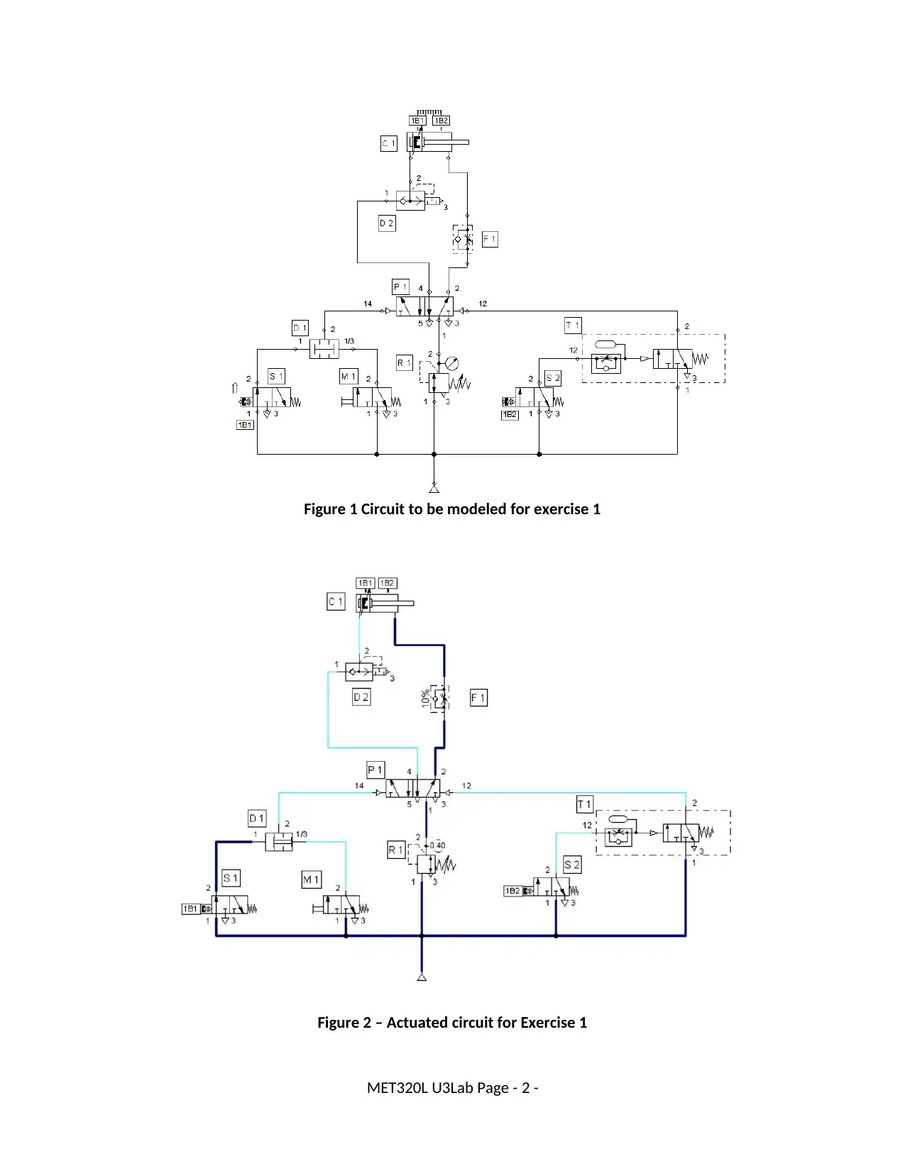
Figure 1 Circuit to be modeled for exercise 1
Figure 2 – Actuated circuit for Exercise 1
MET320L U3Lab Page - 2 -
Figure 2 – Actuated circuit for Exercise 1
MET320L U3Lab Page - 2 -
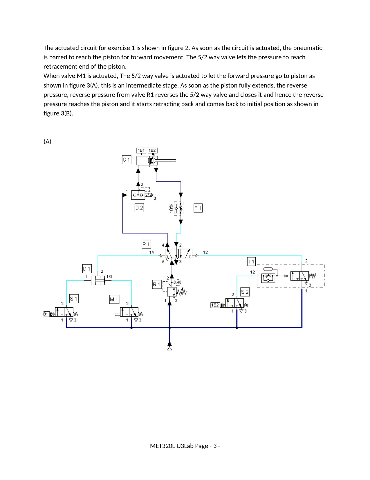
The actuated circuit for exercise 1 is shown in figure 2. As soon as the circuit is actuated, the pneumatic
is barred to reach the piston for forward movement. The 5/2 way valve lets the pressure to reach
retracement end of the piston.
When valve M1 is actuated, The 5/2 way valve is actuated to let the forward pressure go to piston as
shown in figure 3(A), this is an intermediate stage. As soon as the piston fully extends, the reverse
pressure, reverse pressure from valve R1 reverses the 5/2 way valve and closes it and hence the reverse
pressure reaches the piston and it starts retracting back and comes back to initial position as shown in
figure 3(B).
(A)
MET320L U3Lab Page - 3 -
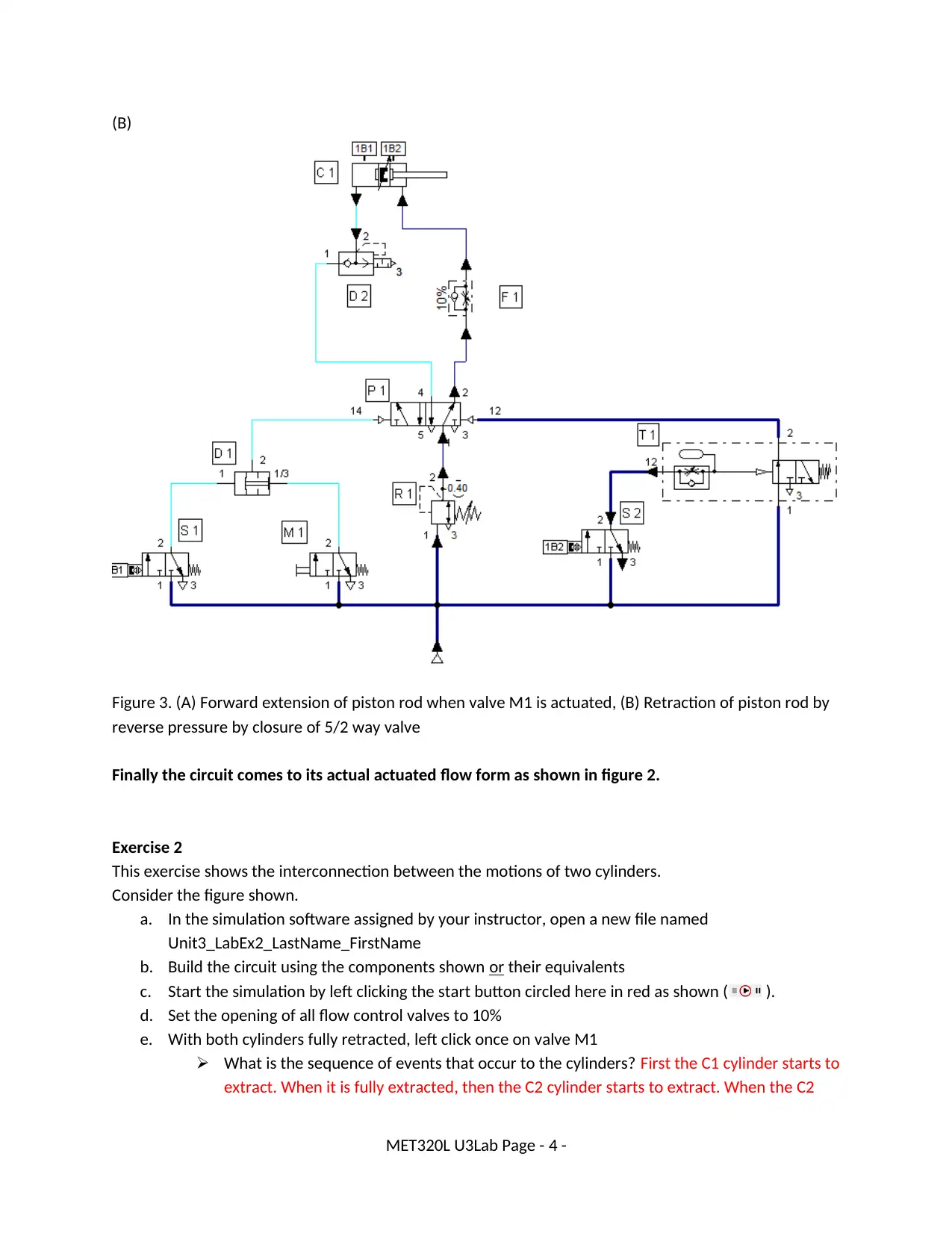
(B)
Figure 3. (A) Forward extension of piston rod when valve M1 is actuated, (B) Retraction of piston rod by
reverse pressure by closure of 5/2 way valve
Finally the circuit comes to its actual actuated flow form as shown in figure 2.
Exercise 2
This exercise shows the interconnection between the motions of two cylinders.
Consider the figure shown.
a. In the simulation software assigned by your instructor, open a new file named
Unit3_LabEx2_LastName_FirstName
b. Build the circuit using the components shown or their equivalents
c. Start the simulation by left clicking the start button circled here in red as shown ( ).
d. Set the opening of all flow control valves to 10%
e. With both cylinders fully retracted, left click once on valve M1
What is the sequence of events that occur to the cylinders? First the C1 cylinder starts to
extract. When it is fully extracted, then the C2 cylinder starts to extract. When the C2
MET320L U3Lab Page - 4 -
Secure Best Marks with AI Grader
Need help grading? Try our AI Grader for instant feedback on your assignments.
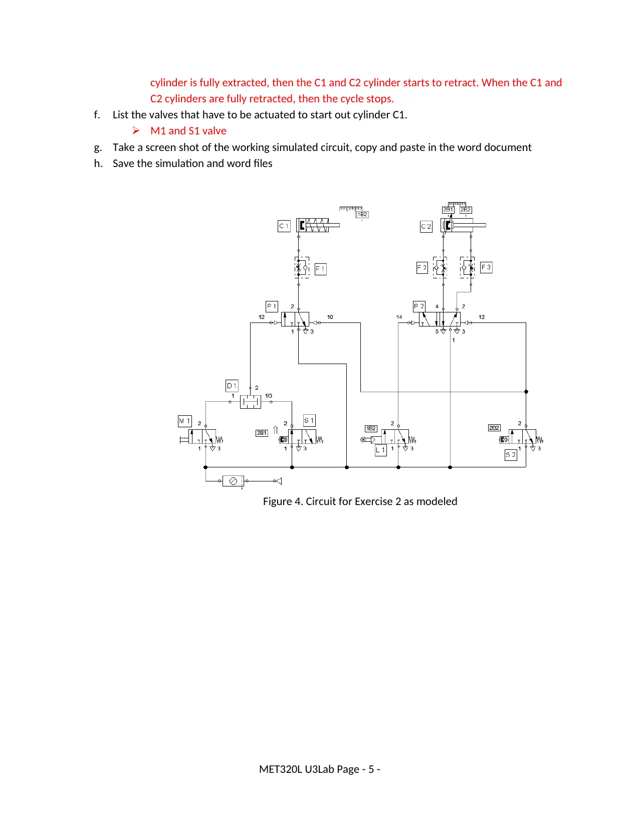
cylinder is fully extracted, then the C1 and C2 cylinder starts to retract. When the C1 and
C2 cylinders are fully retracted, then the cycle stops.
f. List the valves that have to be actuated to start out cylinder C1.
M1 and S1 valve
g. Take a screen shot of the working simulated circuit, copy and paste in the word document
h. Save the simulation and word files
Figure 4. Circuit for Exercise 2 as modeled
MET320L U3Lab Page - 5 -
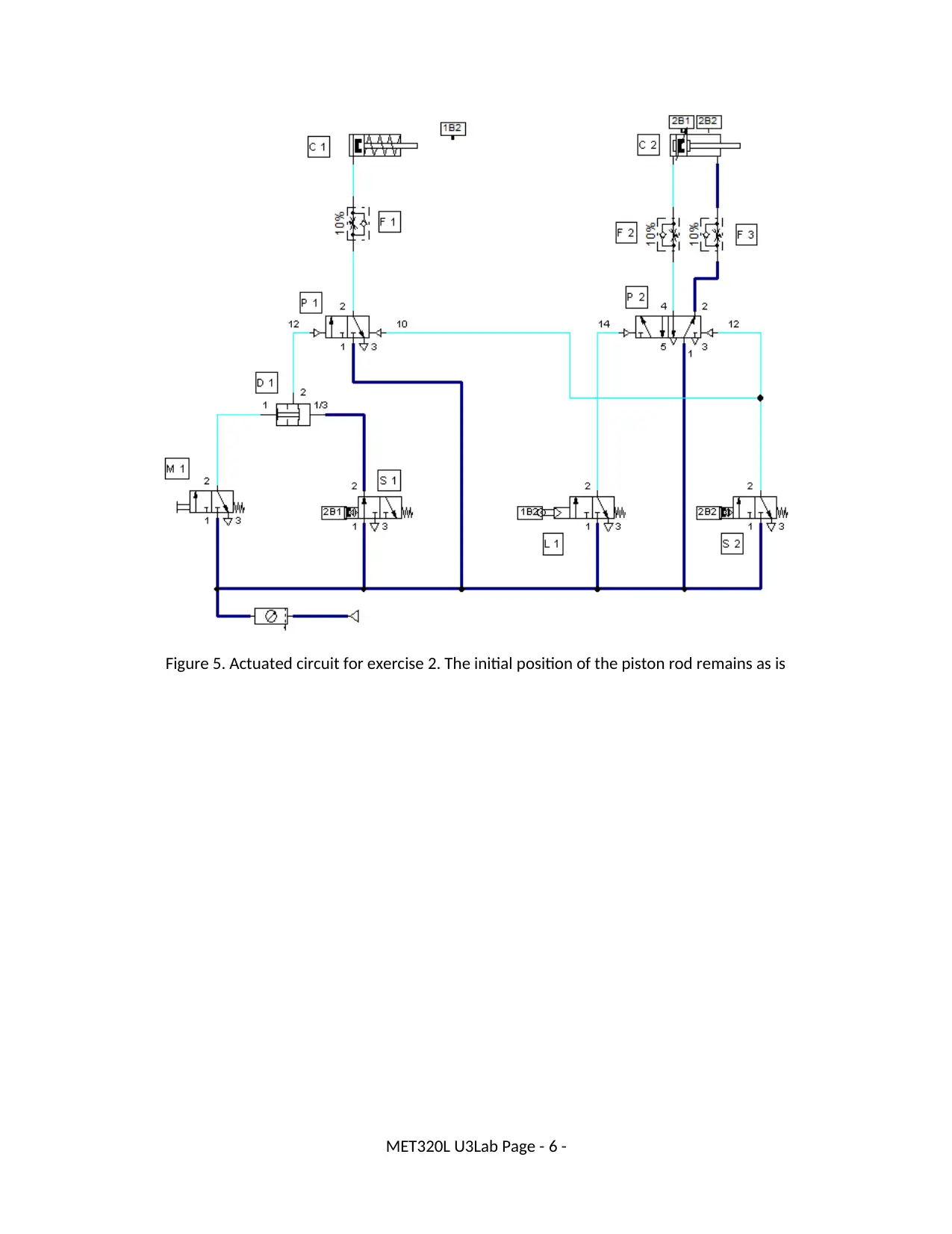
Figure 5. Actuated circuit for exercise 2. The initial position of the piston rod remains as is
MET320L U3Lab Page - 6 -
MET320L U3Lab Page - 6 -
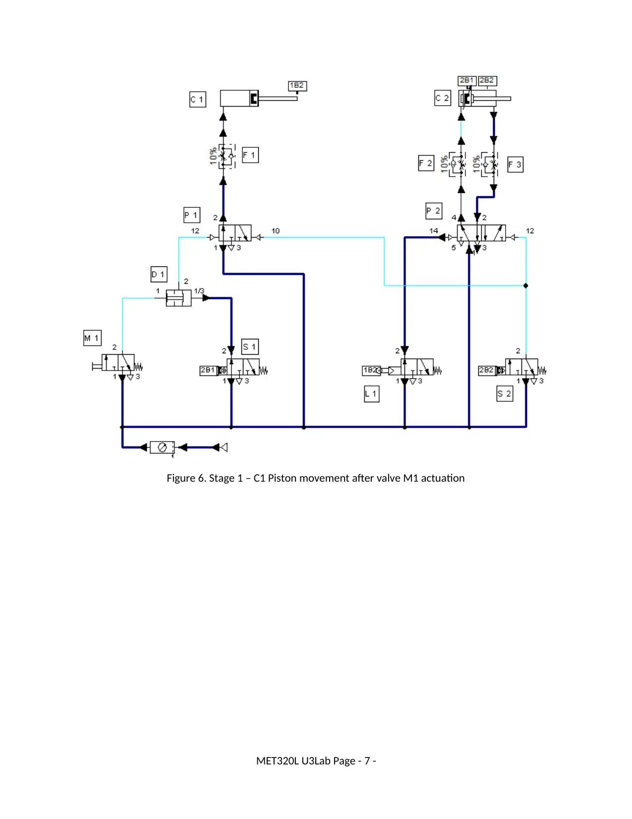
Figure 6. Stage 1 – C1 Piston movement after valve M1 actuation
MET320L U3Lab Page - 7 -
MET320L U3Lab Page - 7 -
Paraphrase This Document
Need a fresh take? Get an instant paraphrase of this document with our AI Paraphraser
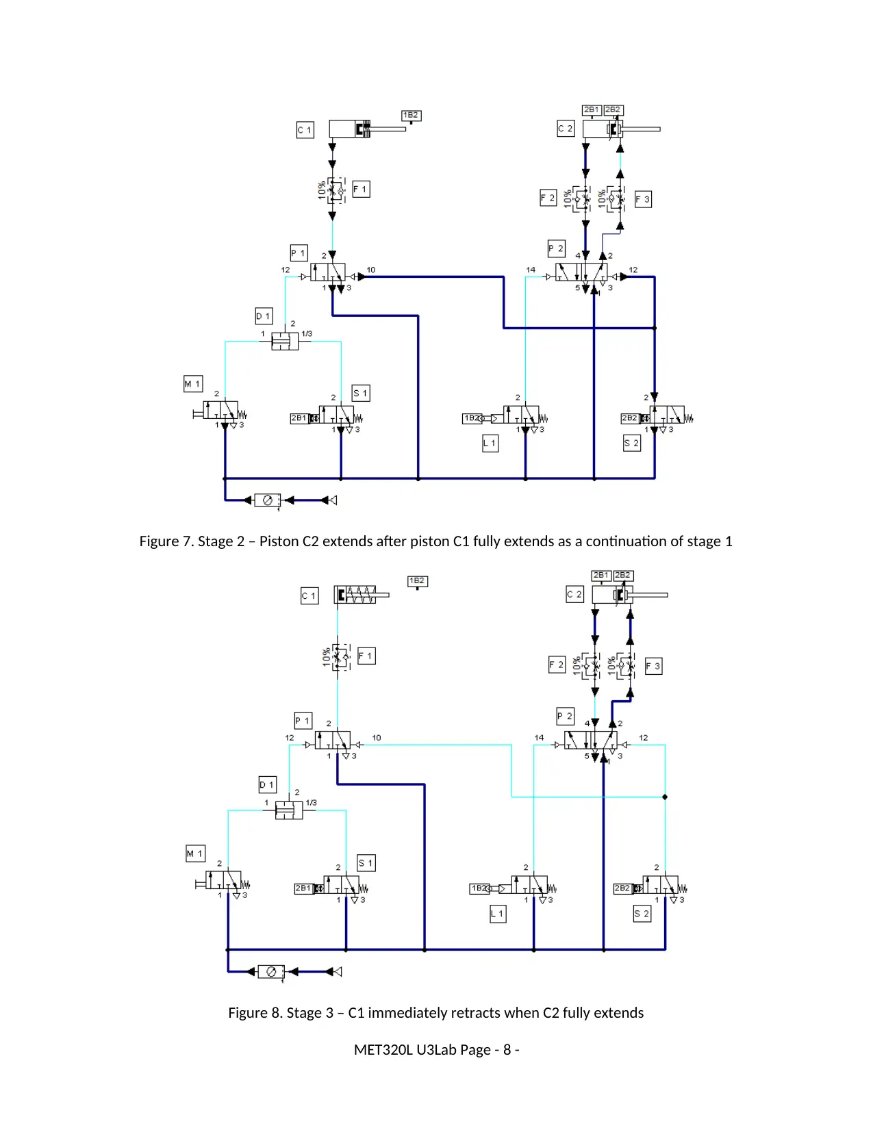
Figure 7. Stage 2 – Piston C2 extends after piston C1 fully extends as a continuation of stage 1
Figure 8. Stage 3 – C1 immediately retracts when C2 fully extends
MET320L U3Lab Page - 8 -
Figure 8. Stage 3 – C1 immediately retracts when C2 fully extends
MET320L U3Lab Page - 8 -
When valve M1 valve is actuated, valve P1 is also actuated and inlet opens by forward pressure. This
pressure actuates the piston C1 and it extends as shown in figure 6. As soon as the piston fully extends,
the pressure bypasses to valve P2 and open it which leads to actuation of piston C2 and it also starts
extending slowly due to control valve. It is shown in figure 7. As soon as both the pistons fully extends,
The reverse pressure builds and valve P1 reverses and closes and piston C1 starts to retract. As soon the
C1 fully retracts, the reverse pressure valve P2 closes and piston C2 starts retracting as shown in figure
8. After both piston fully retracts, all the valves close and circuit comes to halt.
Exercise 3
Consider the electro-pneumatic circuit shown in the figure.
a. In the simulation software assigned by your instructor, open a new file named
Unit3_LabEx3_LastName_FirstName
b. Build the circuit using the components shown or their equivalents
c. Start the simulation by left clicking the start button circled in red as shown ( ).
d. Left click and hold down the momentarily push button S1?
What happens? The 1A1 cylinder starts to extract. When it is fully extracted, then stops.
Why? Because we hold down the momentarily S1 push button, and it switches and
holds the 1V1 valve into cylinder extract position.
e. Release the left mouse button now
What happens? The 1A1 cylinder starts to retract. When it is fully retracted, then stops.
Why? Because we released the S1 push button, and the 1V1 valve returns into initial
position thanks to the mechanical return spring.
f. Take a screen shot of the working simulated circuit, copy and paste in the word document
g. Save the simulation and word files
MET320L U3Lab Page - 9 -
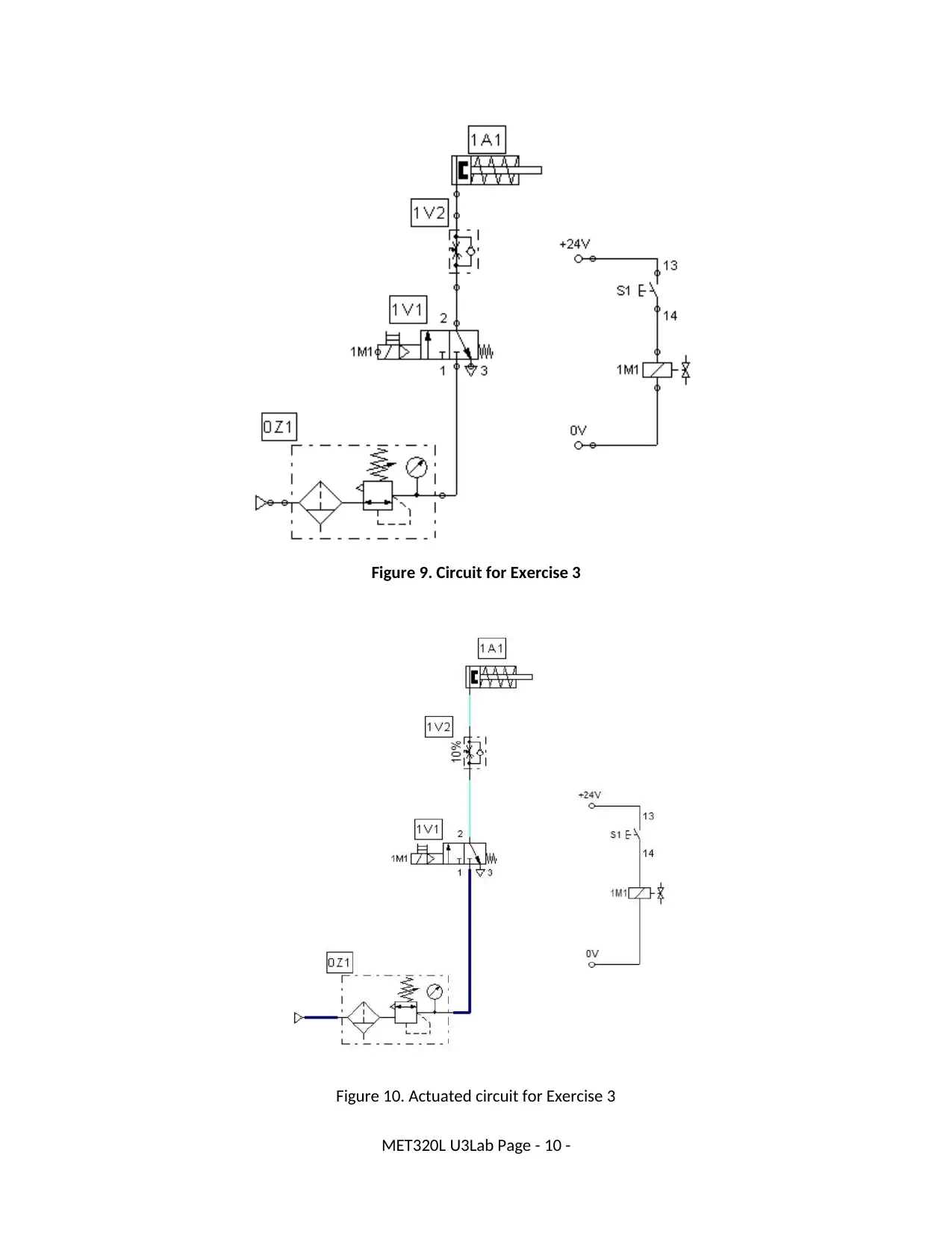
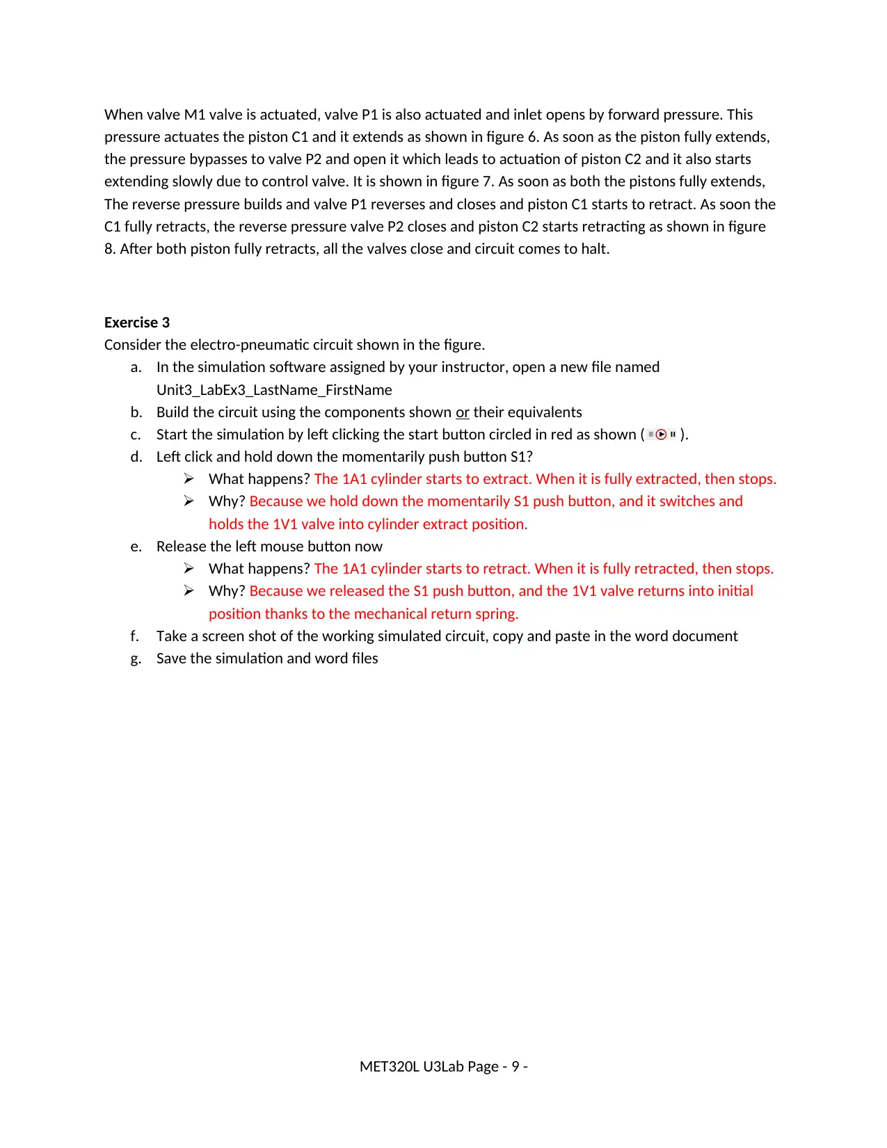
Figure 9. Circuit for Exercise 3
Figure 10. Actuated circuit for Exercise 3
MET320L U3Lab Page - 10 -
Figure 10. Actuated circuit for Exercise 3
MET320L U3Lab Page - 10 -
Secure Best Marks with AI Grader
Need help grading? Try our AI Grader for instant feedback on your assignments.
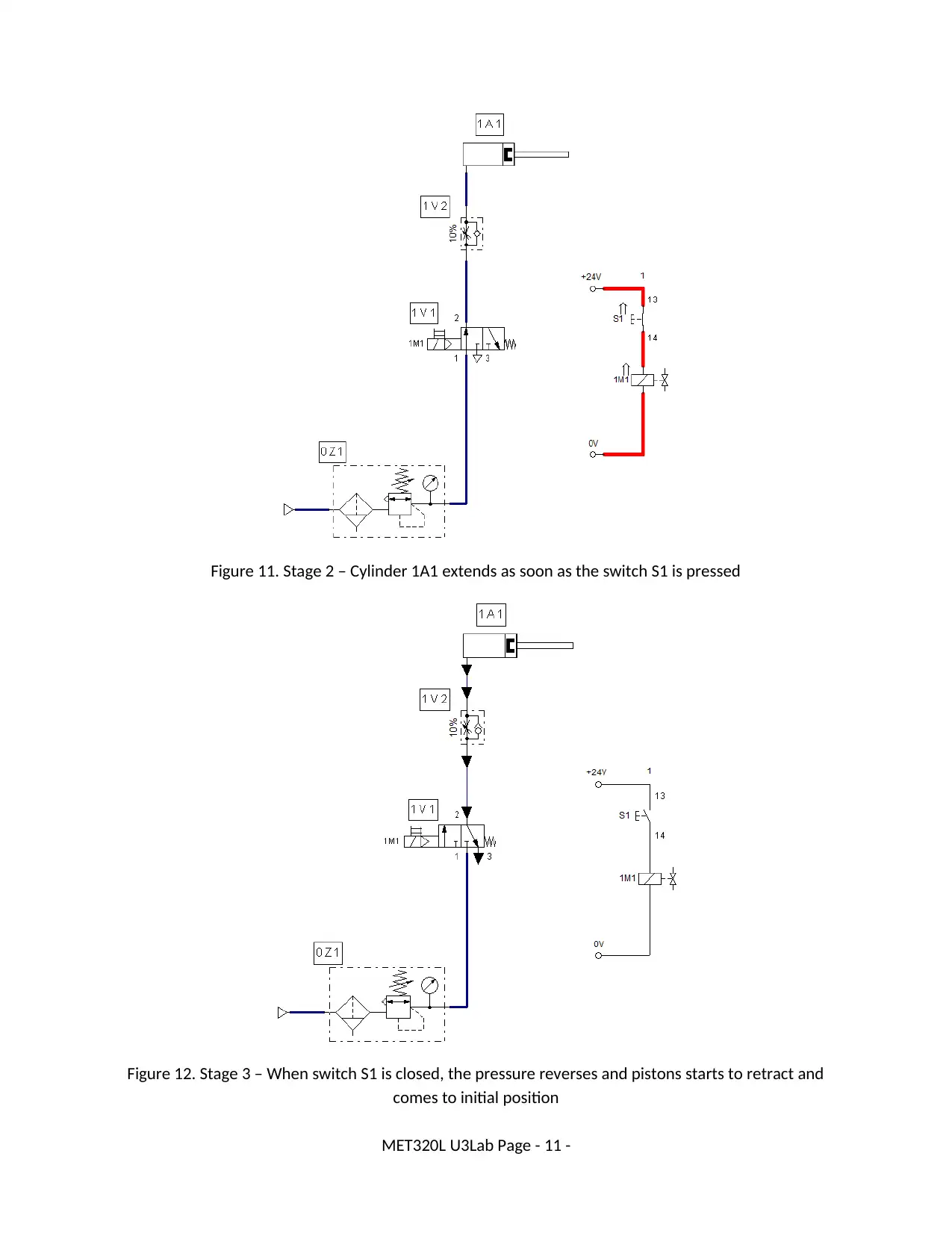
Figure 11. Stage 2 – Cylinder 1A1 extends as soon as the switch S1 is pressed
Figure 12. Stage 3 – When switch S1 is closed, the pressure reverses and pistons starts to retract and
comes to initial position
MET320L U3Lab Page - 11 -
Figure 12. Stage 3 – When switch S1 is closed, the pressure reverses and pistons starts to retract and
comes to initial position
MET320L U3Lab Page - 11 -
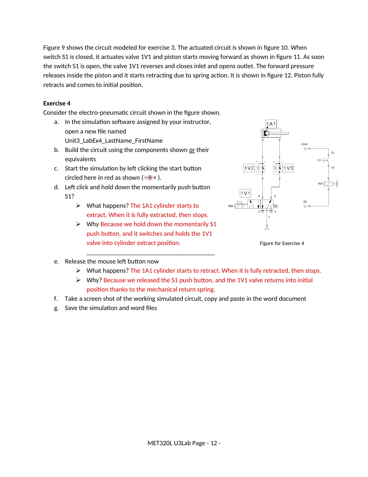
Figure 9 shows the circuit modeled for exercise 3. The actuated circuit is shown in figure 10. When
switch S1 is closed, it actuates valve 1V1 and piston starts moving forward as shown in figure 11. As soon
the switch S1 is open, the valve 1V1 reverses and closes inlet and opens outlet. The forward pressure
releases inside the piston and it starts retracting due to spring action. It is shown in figure 12. Piston fully
retracts and comes to initial position.
Exercise 4
Consider the electro-pneumatic circuit shown in the figure shown.
a. In the simulation software assigned by your instructor,
open a new file named
Unit3_LabEx4_LastName_FirstName
b. Build the circuit using the components shown or their
equivalents
c. Start the simulation by left clicking the start button
circled here in red as shown ( ).
d. Left click and hold down the momentarily push button
S1?
What happens? The 1A1 cylinder starts to
extract. When it is fully extracted, then stops.
Why Because we hold down the momentarily S1
push button, and it switches and holds the 1V1
valve into cylinder extract position. Figure for Exercise 4
_______________________________________
e. Release the mouse left button now
What happens? The 1A1 cylinder starts to retract. When it is fully retracted, then stops.
Why? Because we released the S1 push button, and the 1V1 valve returns into initial
position thanks to the mechanical return spring.
f. Take a screen shot of the working simulated circuit, copy and paste in the word document
g. Save the simulation and word files
MET320L U3Lab Page - 12 -
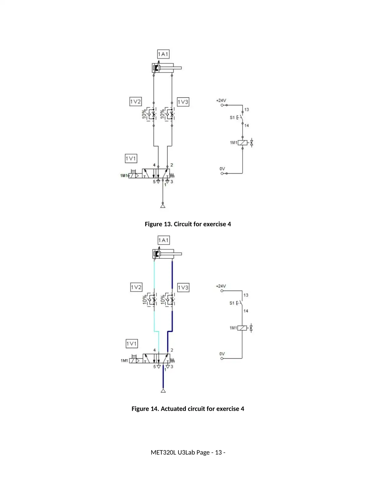
Figure 13. Circuit for exercise 4
Figure 14. Actuated circuit for exercise 4
MET320L U3Lab Page - 13 -
Figure 14. Actuated circuit for exercise 4
MET320L U3Lab Page - 13 -
Paraphrase This Document
Need a fresh take? Get an instant paraphrase of this document with our AI Paraphraser
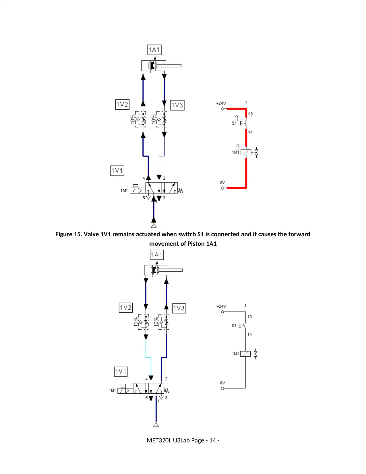
Figure 15. Valve 1V1 remains actuated when switch S1 is connected and it causes the forward
movement of Piston 1A1
MET320L U3Lab Page - 14 -
movement of Piston 1A1
MET320L U3Lab Page - 14 -
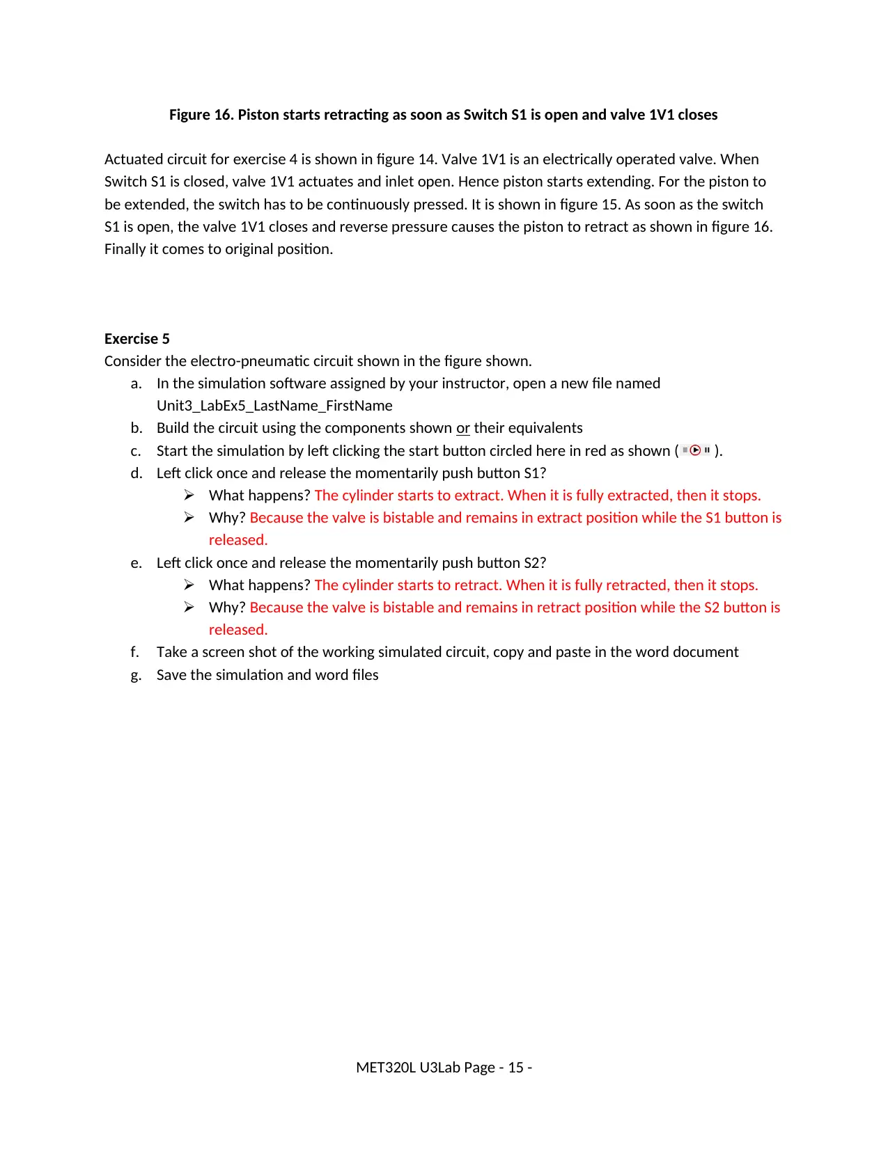
Figure 16. Piston starts retracting as soon as Switch S1 is open and valve 1V1 closes
Actuated circuit for exercise 4 is shown in figure 14. Valve 1V1 is an electrically operated valve. When
Switch S1 is closed, valve 1V1 actuates and inlet open. Hence piston starts extending. For the piston to
be extended, the switch has to be continuously pressed. It is shown in figure 15. As soon as the switch
S1 is open, the valve 1V1 closes and reverse pressure causes the piston to retract as shown in figure 16.
Finally it comes to original position.
Exercise 5
Consider the electro-pneumatic circuit shown in the figure shown.
a. In the simulation software assigned by your instructor, open a new file named
Unit3_LabEx5_LastName_FirstName
b. Build the circuit using the components shown or their equivalents
c. Start the simulation by left clicking the start button circled here in red as shown ( ).
d. Left click once and release the momentarily push button S1?
What happens? The cylinder starts to extract. When it is fully extracted, then it stops.
Why? Because the valve is bistable and remains in extract position while the S1 button is
released.
e. Left click once and release the momentarily push button S2?
What happens? The cylinder starts to retract. When it is fully retracted, then it stops.
Why? Because the valve is bistable and remains in retract position while the S2 button is
released.
f. Take a screen shot of the working simulated circuit, copy and paste in the word document
g. Save the simulation and word files
MET320L U3Lab Page - 15 -
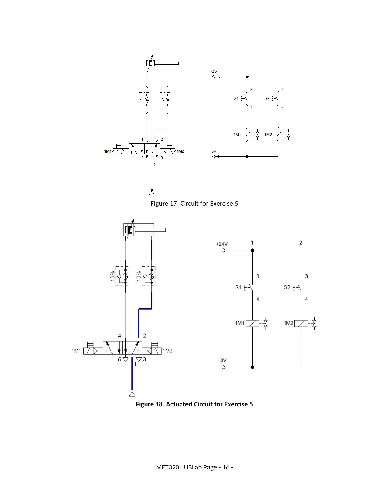
Figure 17. Circuit for Exercise 5
Figure 18. Actuated Circuit for Exercise 5
MET320L U3Lab Page - 16 -
Figure 18. Actuated Circuit for Exercise 5
MET320L U3Lab Page - 16 -
Secure Best Marks with AI Grader
Need help grading? Try our AI Grader for instant feedback on your assignments.
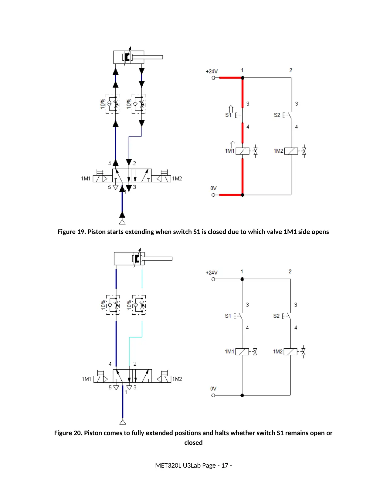
Figure 19. Piston starts extending when switch S1 is closed due to which valve 1M1 side opens
Figure 20. Piston comes to fully extended positions and halts whether switch S1 remains open or
closed
MET320L U3Lab Page - 17 -
Figure 20. Piston comes to fully extended positions and halts whether switch S1 remains open or
closed
MET320L U3Lab Page - 17 -
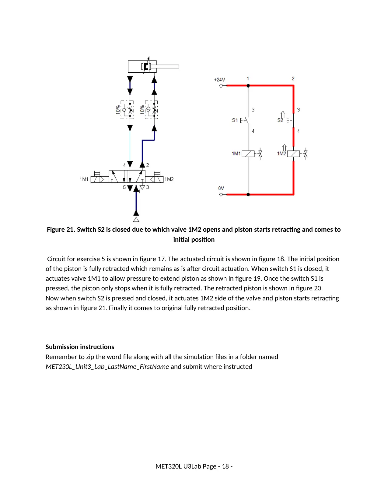
Figure 21. Switch S2 is closed due to which valve 1M2 opens and piston starts retracting and comes to
initial position
Circuit for exercise 5 is shown in figure 17. The actuated circuit is shown in figure 18. The initial position
of the piston is fully retracted which remains as is after circuit actuation. When switch S1 is closed, it
actuates valve 1M1 to allow pressure to extend piston as shown in figure 19. Once the switch S1 is
pressed, the piston only stops when it is fully retracted. The retracted piston is shown in figure 20.
Now when switch S2 is pressed and closed, it actuates 1M2 side of the valve and piston starts retracting
as shown in figure 21. Finally it comes to original fully retracted position.
Submission instructions
Remember to zip the word file along with all the simulation files in a folder named
MET230L_Unit3_Lab_LastName_FirstName and submit where instructed
MET320L U3Lab Page - 18 -
1 out of 18
Related Documents


Your All-in-One AI-Powered Toolkit for Academic Success.
+13062052269
info@desklib.com
Available 24*7 on WhatsApp / Email
![[object Object]](/_next/static/media/star-bottom.7253800d.svg)
Unlock your academic potential
© 2024 | Zucol Services PVT LTD | All rights reserved.