Metal Foam Composite Modelling
VerifiedAdded on 2023/03/17
|77
|15216
|69
AI Summary
This research project explores the manufacturing methods, properties, and applications of metal foams. It covers topics such as thermal conductivity, electrical properties, and various mathematical formulas. The study also includes a detailed analysis of mechanical and thermal properties of metal foams.
Contribute Materials
Your contribution can guide someone’s learning journey. Share your
documents today.
Metal Foam Composite Modelling Title of the Research Project
<Student Name>
<Student Number>
A report submitted for
300598 Master Project 2
in partial fulfilment of the requirements for the degree of
Master of Engineering
Supervisor: <XXX>
School of Computing, Engineering and Mathematics
Western Sydney University
June 2019
1
<Student Name>
<Student Number>
A report submitted for
300598 Master Project 2
in partial fulfilment of the requirements for the degree of
Master of Engineering
Supervisor: <XXX>
School of Computing, Engineering and Mathematics
Western Sydney University
June 2019
1
Secure Best Marks with AI Grader
Need help grading? Try our AI Grader for instant feedback on your assignments.

ABSTRACT
2
2

ACKNOWLEDGMENTS
3
3
TABLE OF CONTENTS
ABSTRACT.....................................................................................................................................2
ACKNOWLEDGMENTS...............................................................................................................3
TABLE OF CONTENTS.................................................................................................................4
LIST OF TABLES...........................................................................................................................6
LIST OF FIGURES.........................................................................................................................7
CHAPTER I: INTRODUCTION.....................................................................................................8
Introduction:.................................................................................................................................8
Methods of Manufacturing Metal Foams.....................................................................................8
Metal Form Properties...............................................................................................................10
Thermal properties.................................................................................................................11
Electrical properties...............................................................................................................12
Other Mathematical Formulas....................................................................................................12
Thermal conductivity.............................................................................................................12
Viscosity model......................................................................................................................14
Physical mixture rule.................................................................................................................15
Nano particles Properties...........................................................................................................16
Foam Selection of Materials......................................................................................................16
Foam Profile Property................................................................................................................17
Foam Yield Phenomenon.......................................................................................................17
Foam Specimen Fatigue Testing............................................................................................17
4
Secure Best Marks with AI Grader
Need help grading? Try our AI Grader for instant feedback on your assignments.
Foam Specimen Creep Test...................................................................................................18
Vibration absorption..............................................................................................................18
Cutting and Joining Operations..............................................................................................18
Metal Form Cost Analysis.........................................................................................................18
Simulation Methods used in Metal Foams.................................................................................19
Metal Foams Applications.........................................................................................................20
Aims and Objectives..................................................................................................................21
CHAPTER II: LITERATURE REVIEW......................................................................................22
CHAPTER III: METHODOLOGY...............................................................................................40
Thermal conductivity in relation to density...........................................................................42
Thermal conductivity in relation reinforcement percentage..................................................42
The rule of physical mixture......................................................................................................44
Properties of metal foam............................................................................................................44
CHAPTER IV: RESULTS AND ANALYSIS..............................................................................46
Mechanical properties................................................................................................................46
Open-cell type foam...............................................................................................................46
Closed-cell type foam............................................................................................................52
Thermal properties.....................................................................................................................61
Thermal conductivity in respect to density............................................................................61
Thermal conductivity in respect to % of reinforcement.........................................................63
CHAPTER VI: CONCLUSION....................................................................................................73
REFERENCES...............................................................................................................................74
5
LIST OF TABLES
Table 1.1 Properties of metallic form and their formulas
Table 1.2 Properties of composites
Table 2.1 Aluminium foams
Table 2.2 Surface roughness
Table 2.3 comparison of conventional foam with the composite foam
Table 3.1 Mechanical properties of metal foam
Table 3.2 Properties of composites
9
15
26
31
36
40
43
6
LIST OF FIGURES
Figure 2.1 Ceast fractovis drop test
Figure 1.2 NaCl samples under different pressure condition 32, 39 and 50 psi
Figure 2.3 Geometry of the model
Figure 2.4 Three-point bending test
Figure 4.1: Compressive strength for all metal foams
Figure 4.2: Hardness for all metal foams
Figure 4.3: Young’s modulus for all metal foams
Figure 4.4 Variation of K vs q for all metal foams
Figure 4.5 Variation of K vs phi for Mixture rule
Figure 4.6 Variation of K vs phi for Maxwell model
Figure 4.7 Variation of K vs phi for Hamilton & Crosser model (n=3)
Figure 4.8 Variation of K vs phi for Hamilton & Crosser model (n=2)
Figure 4.9 Variation of K vs phi for Hamilton & Crosser model (n=1)
25
25
30
33
52
52
53
55
57
59
63
63
64
7
Paraphrase This Document
Need a fresh take? Get an instant paraphrase of this document with our AI Paraphraser
CHAPTER I: INTRODUCTION
Introduction:
There are classifications of metal foams in accordance with the materials’ low density, high
capacity to absorb energy, high capacity to conduct heat, ability to absorb vibration and high
noise. In addition, the material could have high mechanical, electrical, acoustic and physical
qualities. These foams avail light weigh capability to their structures other than being cheap.in
addition, they can offer stiffness to relevant structures to increase the structure’s energy. Metal
foams are non-toxic and are recyclable making them suitable. Examples of metal foams include;
SiC, Al, Nanoporous gold and Nanoporous carbon.
Methods of Manufacturing Metal Foams
There are ways of developing metal foams from various materials and methods. There exist nine
manufacturing methods for metal foams, however, only five methods are mostly used and are
well advanced. The process of selecting the production method has been proving difficult and
needs deep experience and knowledge. The list below represents the nine methods able to be
used in the development of metal foams.
1. Power pressurization of metal through leaching powder.
2. Trapping high-pressure gas through the use of isostatic pressing.
3. Dissolving hydrogen gas in liquid metal in an action pressure.
4. Cooling metal through foam agents in the pressure-controlled system.
5. Sintering hollow sphere before dehydrating.
6. Gas bubbling through metals.
8
7. Forming wax mould.
8. Vapour phases disposing of.
9. Metal powder collections through foam agents before heating.
The methods mentioned above can be used in metal foam production in four forms, the metal
foams can be produced as vapour phases, production as aqueous solutions that are metallic foam
electro-deposition, production in a liquid state using the liquid processes and production in the
solid state. These four methods are able to be used in the production of metal foams and lead to
various cell size and relative density.
Characterizing and testing of the metal foam produced is advisable once manufacturing is
complete, there may be a produced metal foam with different cellular structure and property due
to the effect of the selected manufacturing method. In addition, there are many ways of
performing structure analysis present for the characterization of foam. For example, Scanning
Electron Microscopy, optical microscopy and X-ray tomography. Metal foam properties
production is influenced by the size of the specimen and the size of the cell. Various methods are
present for conducting analysis on the specimen metal foams. Below is a prepared list which
could be used in analyzing the metal foams to note the different metal foam behaviours.
1. Specimen’s creep test.
2. Specimen’s fatigue tees.
3. Specimen’s shear test.
4. Specimen’s indentation test.
5. Specimen’s multi-axial stress testing.
6. Specimen’s uniaxial compression testing.
7. Specimen’s Uniaxial tension testing.
9
Metal Form Properties
The cellular structure of metal foam affects their properties. Additionally, the method used in
manufacturing, and the cell type (closed or open) affect the metal foam properties. More
influence on the metal foam properties are also affected by the shapes, defects, sizes as well as
the anisotropy present in the materials. The distinction between properties present in the solid
materials and foam material are that solid materials will be represented by subscript ‘s’ while
properties for the metal foams will be represented by ρs and ρ.
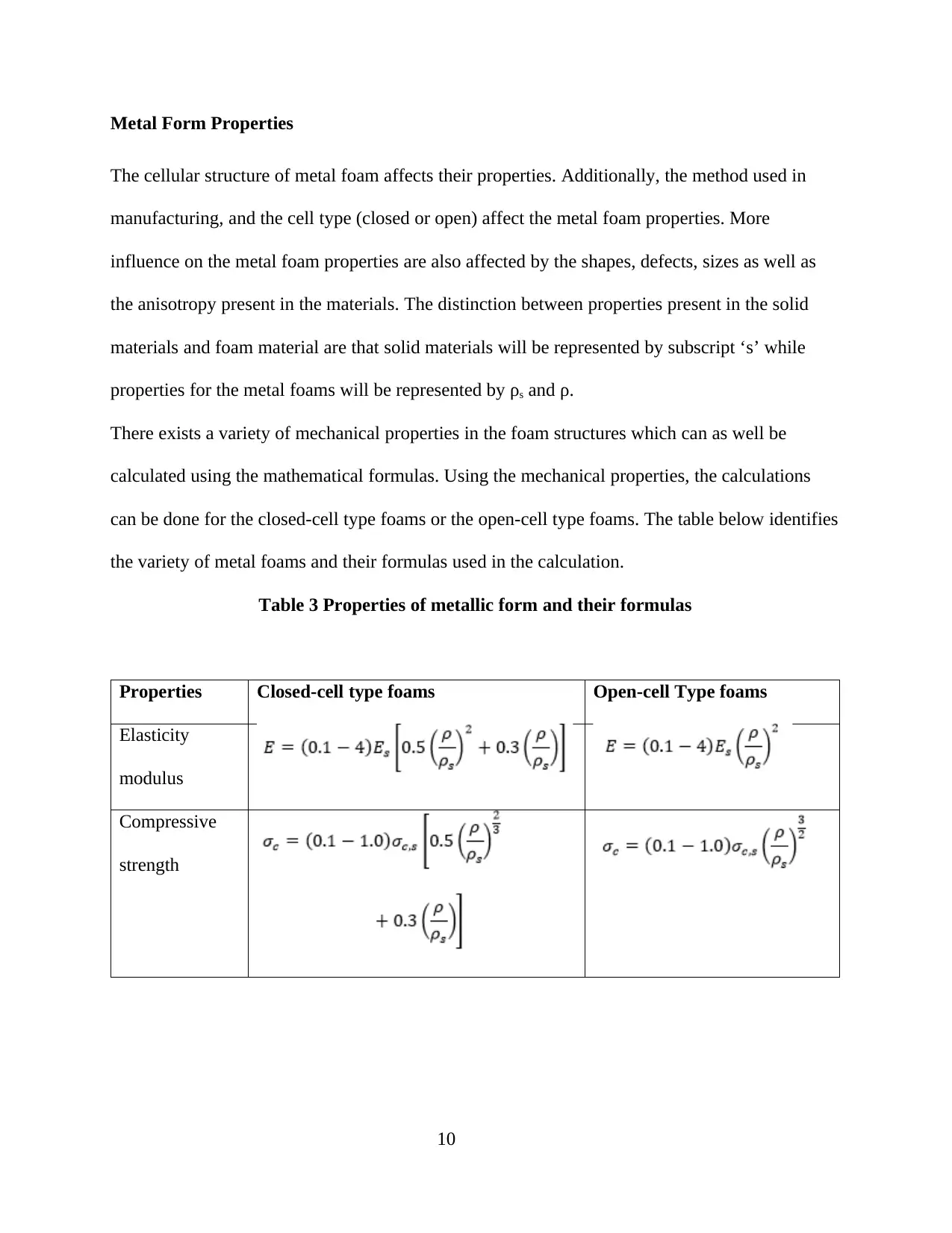
There exists a variety of mechanical properties in the foam structures which can as well be
calculated using the mathematical formulas. Using the mechanical properties, the calculations
can be done for the closed-cell type foams or the open-cell type foams. The table below identifies
the variety of metal foams and their formulas used in the calculation.
Table 3 Properties of metallic form and their formulas
Properties Closed-cell type foams Open-cell Type foams
Elasticity
modulus
Compressive
strength
10
Secure Best Marks with AI Grader
Need help grading? Try our AI Grader for instant feedback on your assignments.
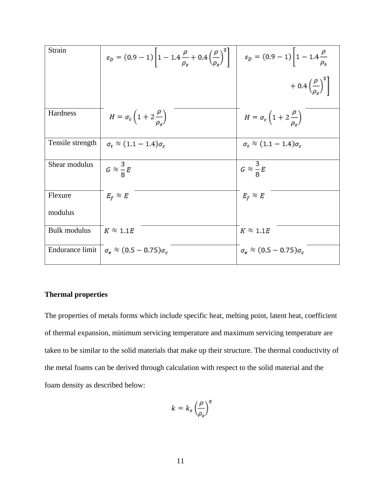
Strain
Hardness
Tensile strength
Shear modulus
Flexure
modulus
Bulk modulus
Endurance limit
Thermal properties
The properties of metals forms which include specific heat, melting point, latent heat, coefficient
of thermal expansion, minimum servicing temperature and maximum servicing temperature are
taken to be similar to the solid materials that make up their structure. The thermal conductivity of
the metal foams can be derived through calculation with respect to the solid material and the
foam density as described below:
11
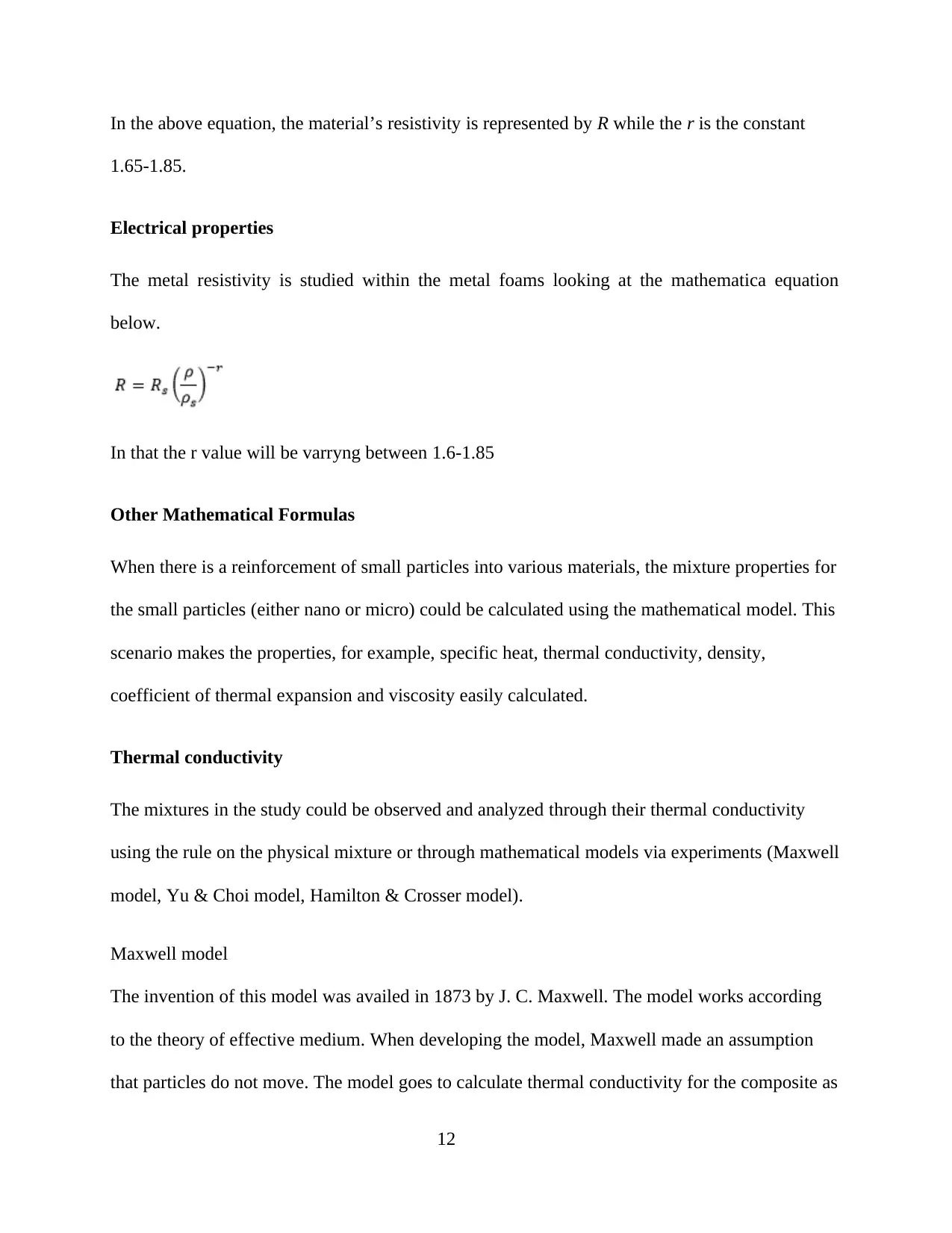
In the above equation, the material’s resistivity is represented by R while the r is the constant
1.65-1.85.
Electrical properties
The metal resistivity is studied within the metal foams looking at the mathematica equation
below.
In that the r value will be varryng between 1.6-1.85
Other Mathematical Formulas
When there is a reinforcement of small particles into various materials, the mixture properties for
the small particles (either nano or micro) could be calculated using the mathematical model. This
scenario makes the properties, for example, specific heat, thermal conductivity, density,
coefficient of thermal expansion and viscosity easily calculated.
Thermal conductivity
The mixtures in the study could be observed and analyzed through their thermal conductivity
using the rule on the physical mixture or through mathematical models via experiments (Maxwell
model, Yu & Choi model, Hamilton & Crosser model).
Maxwell model
The invention of this model was availed in 1873 by J. C. Maxwell. The model works according
to the theory of effective medium. When developing the model, Maxwell made an assumption
that particles do not move. The model goes to calculate thermal conductivity for the composite as
12
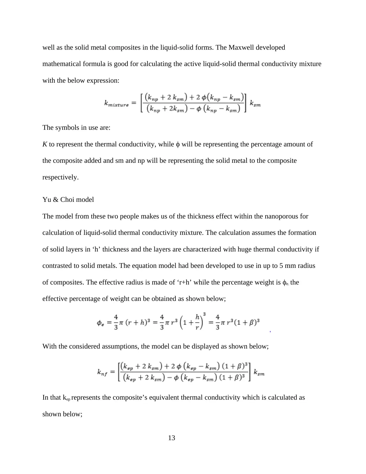
well as the solid metal composites in the liquid-solid forms. The Maxwell developed
mathematical formula is good for calculating the active liquid-solid thermal conductivity mixture
with the below expression:
The symbols in use are:
K to represent the thermal conductivity, while ϕ will be representing the percentage amount of
the composite added and sm and np will be representing the solid metal to the composite
respectively.
Yu & Choi model
The model from these two people makes us of the thickness effect within the nanoporous for
calculation of liquid-solid thermal conductivity mixture. The calculation assumes the formation
of solid layers in ‘h’ thickness and the layers are characterized with huge thermal conductivity if
contrasted to solid metals. The equation model had been developed to use in up to 5 mm radius
of composites. The effective radius is made of ‘r+h’ while the percentage weight is ϕe. the
effective percentage of weight can be obtained as shown below;
With the considered assumptions, the model can be displayed as shown below;
In that kep represents the composite’s equivalent thermal conductivity which is calculated as
shown below;
13
Paraphrase This Document
Need a fresh take? Get an instant paraphrase of this document with our AI Paraphraser
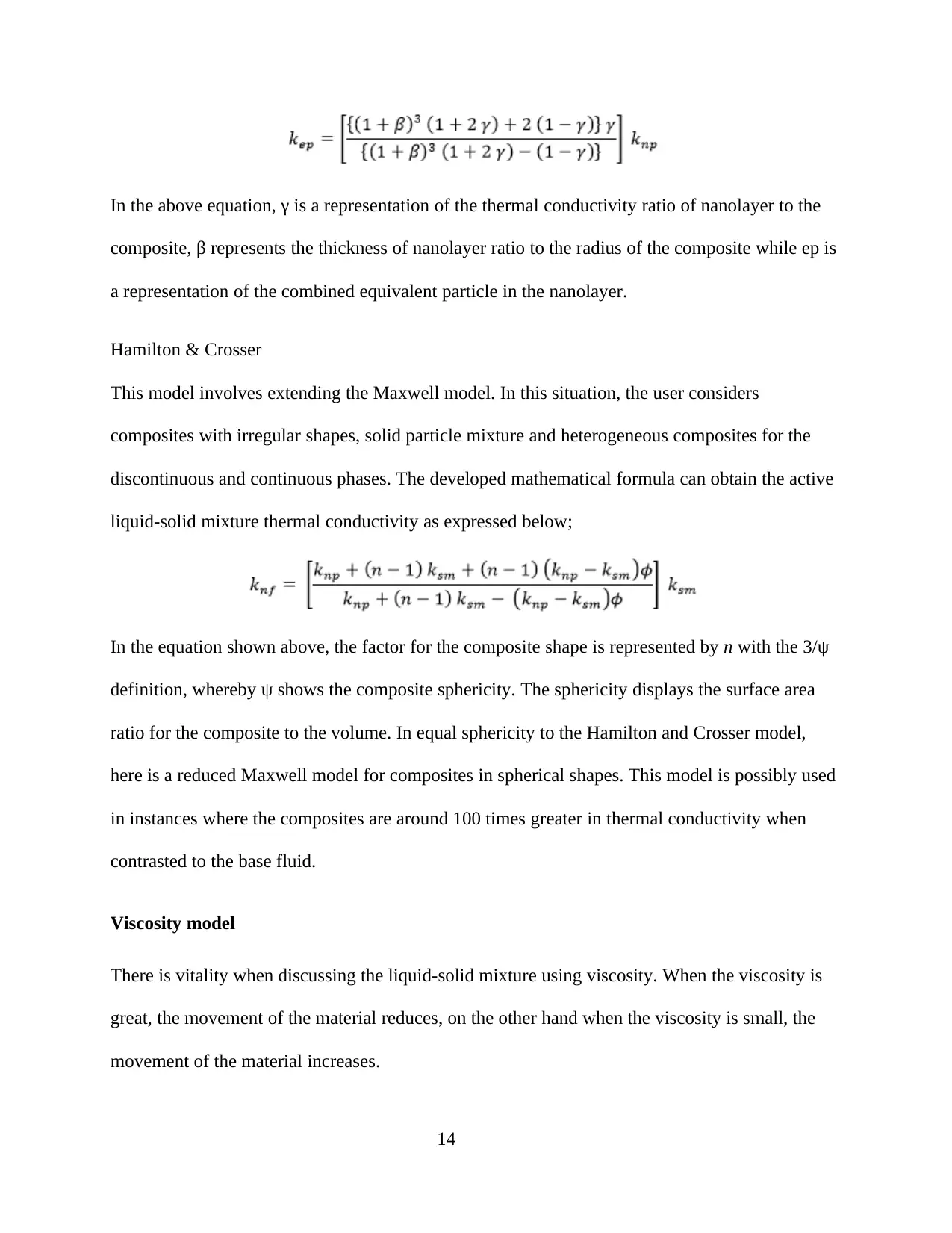
In the above equation, γ is a representation of the thermal conductivity ratio of nanolayer to the
composite, β represents the thickness of nanolayer ratio to the radius of the composite while ep is
a representation of the combined equivalent particle in the nanolayer.
Hamilton & Crosser
This model involves extending the Maxwell model. In this situation, the user considers
composites with irregular shapes, solid particle mixture and heterogeneous composites for the
discontinuous and continuous phases. The developed mathematical formula can obtain the active
liquid-solid mixture thermal conductivity as expressed below;
In the equation shown above, the factor for the composite shape is represented by n with the 3/ψ
definition, whereby ψ shows the composite sphericity. The sphericity displays the surface area
ratio for the composite to the volume. In equal sphericity to the Hamilton and Crosser model,
here is a reduced Maxwell model for composites in spherical shapes. This model is possibly used
in instances where the composites are around 100 times greater in thermal conductivity when
contrasted to the base fluid.
Viscosity model
There is vitality when discussing the liquid-solid mixture using viscosity. When the viscosity is
great, the movement of the material reduces, on the other hand when the viscosity is small, the
movement of the material increases.
14
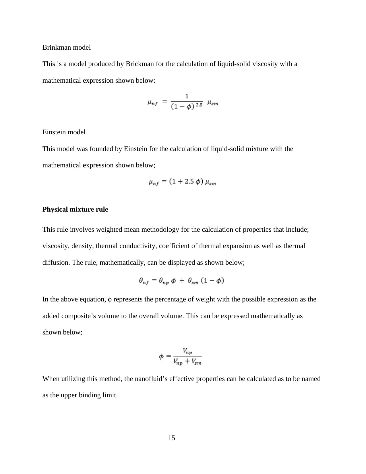
Brinkman model
This is a model produced by Brickman for the calculation of liquid-solid viscosity with a
mathematical expression shown below:
Einstein model
This model was founded by Einstein for the calculation of liquid-solid mixture with the
mathematical expression shown below;
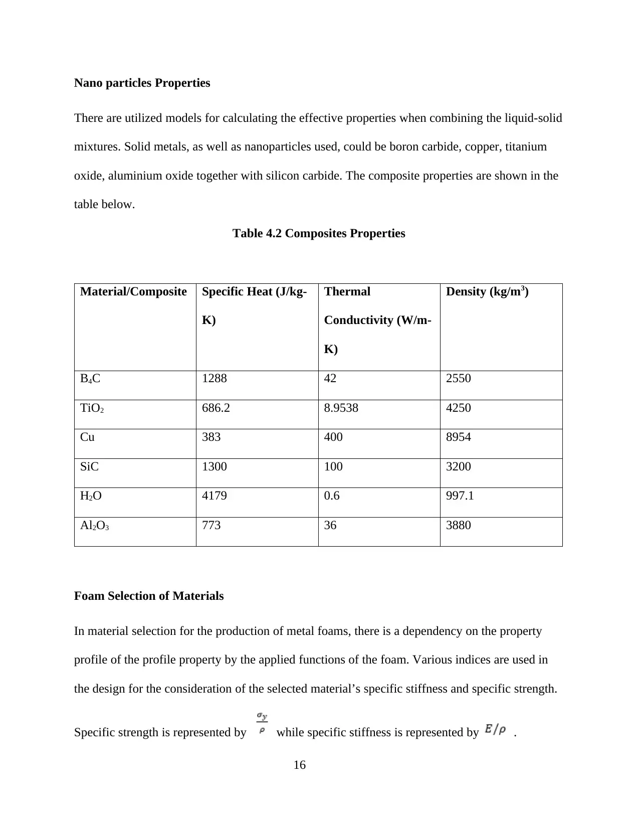
Physical mixture rule
This rule involves weighted mean methodology for the calculation of properties that include;
viscosity, density, thermal conductivity, coefficient of thermal expansion as well as thermal
diffusion. The rule, mathematically, can be displayed as shown below;
In the above equation, ϕ represents the percentage of weight with the possible expression as the
added composite’s volume to the overall volume. This can be expressed mathematically as
shown below;
When utilizing this method, the nanofluid’s effective properties can be calculated as to be named
as the upper binding limit.
15
Nano particles Properties
There are utilized models for calculating the effective properties when combining the liquid-solid
mixtures. Solid metals, as well as nanoparticles used, could be boron carbide, copper, titanium
oxide, aluminium oxide together with silicon carbide. The composite properties are shown in the
table below.
Table 4.2 Composites Properties
Material/Composite Specific Heat (J/kg-
K)
Thermal
Conductivity (W/m-
K)
Density (kg/m3)
B4C 1288 42 2550
TiO2 686.2 8.9538 4250
Cu 383 400 8954
SiC 1300 100 3200
H2O 4179 0.6 997.1
Al2O3 773 36 3880
Foam Selection of Materials
In material selection for the production of metal foams, there is a dependency on the property
profile of the profile property by the applied functions of the foam. Various indices are used in
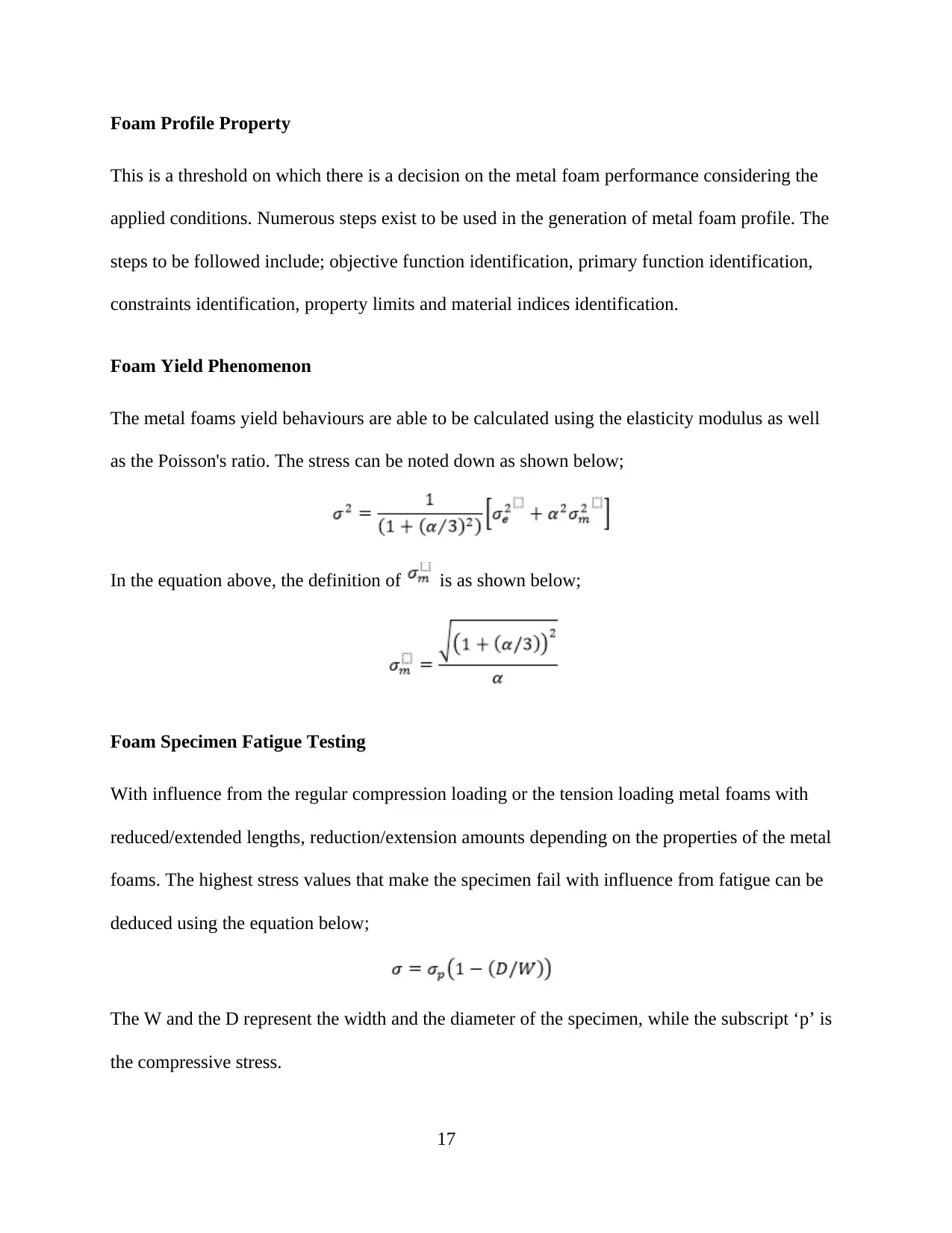
the design for the consideration of the selected material’s specific stiffness and specific strength.
Specific strength is represented by while specific stiffness is represented by .
16
Secure Best Marks with AI Grader
Need help grading? Try our AI Grader for instant feedback on your assignments.
Foam Profile Property
This is a threshold on which there is a decision on the metal foam performance considering the
applied conditions. Numerous steps exist to be used in the generation of metal foam profile. The
steps to be followed include; objective function identification, primary function identification,
constraints identification, property limits and material indices identification.
Foam Yield Phenomenon
The metal foams yield behaviours are able to be calculated using the elasticity modulus as well
as the Poisson's ratio. The stress can be noted down as shown below;
In the equation above, the definition of is as shown below;
Foam Specimen Fatigue Testing
With influence from the regular compression loading or the tension loading metal foams with
reduced/extended lengths, reduction/extension amounts depending on the properties of the metal
foams. The highest stress values that make the specimen fail with influence from fatigue can be
deduced using the equation below;
The W and the D represent the width and the diameter of the specimen, while the subscript ‘p’ is
the compressive stress.
17
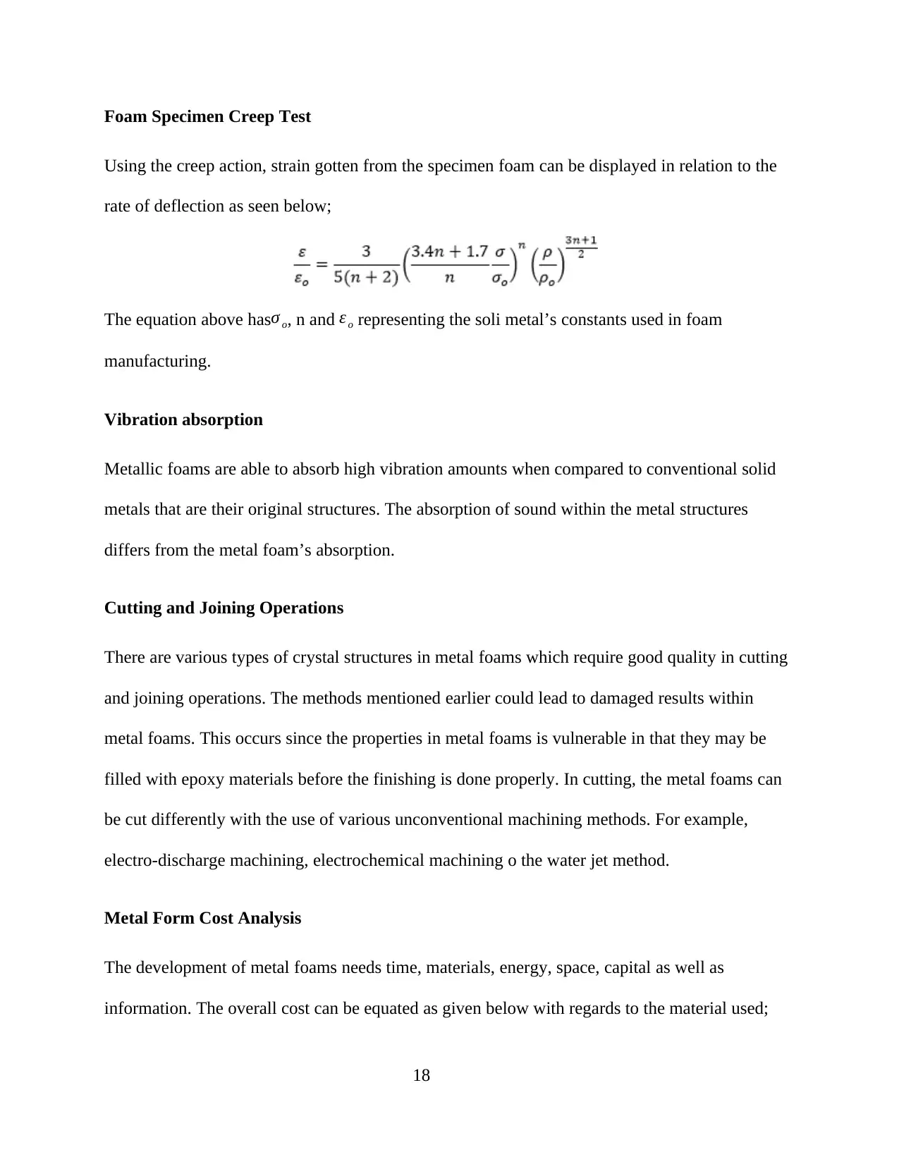
Foam Specimen Creep Test
Using the creep action, strain gotten from the specimen foam can be displayed in relation to the
rate of deflection as seen below;
The equation above hasσ o, n and ε o representing the soli metal’s constants used in foam
manufacturing.
Vibration absorption
Metallic foams are able to absorb high vibration amounts when compared to conventional solid
metals that are their original structures. The absorption of sound within the metal structures
differs from the metal foam’s absorption.
Cutting and Joining Operations
There are various types of crystal structures in metal foams which require good quality in cutting
and joining operations. The methods mentioned earlier could lead to damaged results within
metal foams. This occurs since the properties in metal foams is vulnerable in that they may be
filled with epoxy materials before the finishing is done properly. In cutting, the metal foams can
be cut differently with the use of various unconventional machining methods. For example,
electro-discharge machining, electrochemical machining o the water jet method.
Metal Form Cost Analysis
The development of metal foams needs time, materials, energy, space, capital as well as
information. The overall cost can be equated as given below with regards to the material used;
18
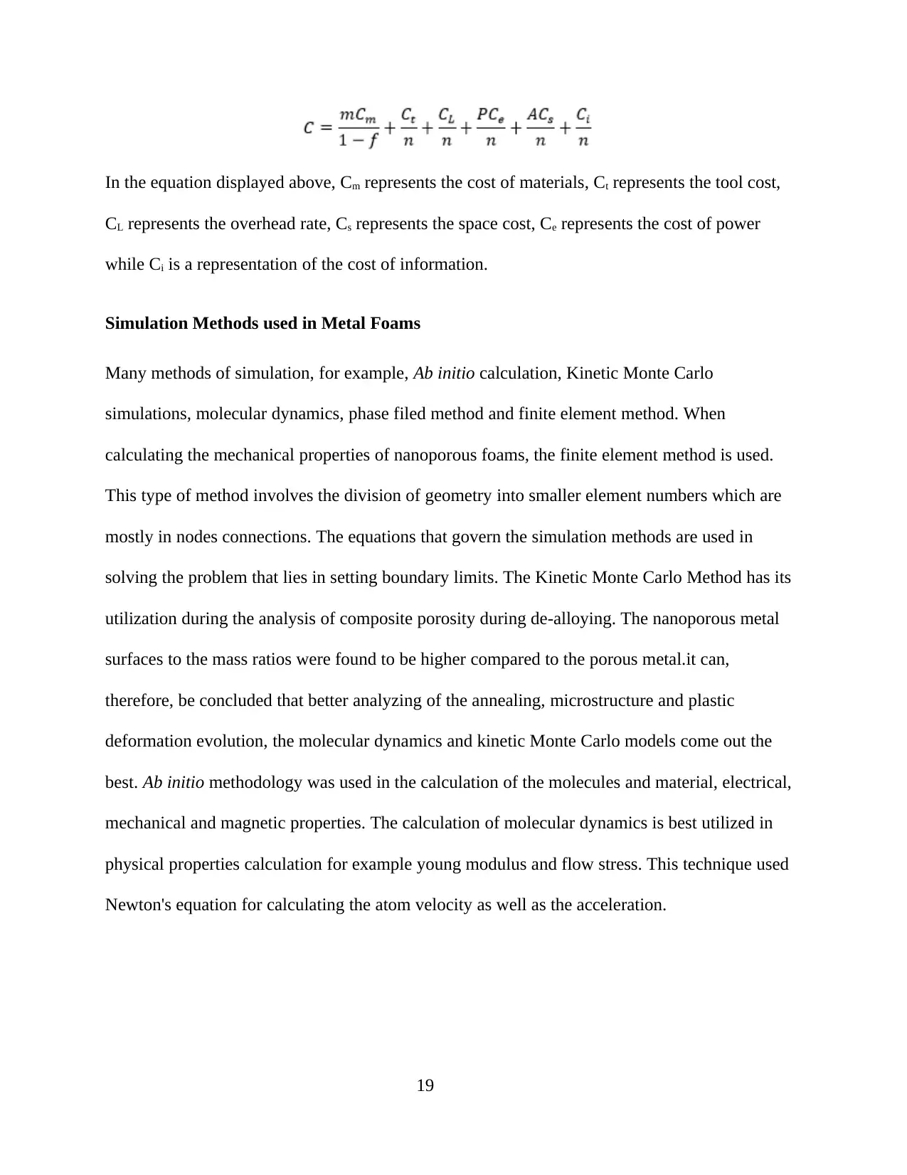
In the equation displayed above, Cm represents the cost of materials, Ct represents the tool cost,
CL represents the overhead rate, Cs represents the space cost, Ce represents the cost of power
while Ci is a representation of the cost of information.
Simulation Methods used in Metal Foams
Many methods of simulation, for example, Ab initio calculation, Kinetic Monte Carlo
simulations, molecular dynamics, phase filed method and finite element method. When
calculating the mechanical properties of nanoporous foams, the finite element method is used.
This type of method involves the division of geometry into smaller element numbers which are
mostly in nodes connections. The equations that govern the simulation methods are used in
solving the problem that lies in setting boundary limits. The Kinetic Monte Carlo Method has its
utilization during the analysis of composite porosity during de-alloying. The nanoporous metal
surfaces to the mass ratios were found to be higher compared to the porous metal.it can,
therefore, be concluded that better analyzing of the annealing, microstructure and plastic
deformation evolution, the molecular dynamics and kinetic Monte Carlo models come out the
best. Ab initio methodology was used in the calculation of the molecules and material, electrical,
mechanical and magnetic properties. The calculation of molecular dynamics is best utilized in
physical properties calculation for example young modulus and flow stress. This technique used
Newton's equation for calculating the atom velocity as well as the acceleration.
19
Paraphrase This Document
Need a fresh take? Get an instant paraphrase of this document with our AI Paraphraser
Metal Foams Applications
Numerous applications of exists, used within the development of metal foams thereby enhancing
the final product performance. Metal foams applications are divided into four major divisions
that include functional applications, structural applications and art and design decorations. In this
section, the applications have been categorized depending on the metal foam used, for example,
aluminium foam, porous silicon foam and porous gold foams.
In the production of lightweight constructions, the aluminium foams prove to be
important [Banhart, 2007].
The utilized aluminium foams can be used as energy absorbers since they help in
vibration absorption [Banhart, 2007].
The aluminium foam sandwich has a lightweight and is being used in replacing sections
of conventional steel [Banhart, 2007].
For instances of crash absorbers, aluminium foam is used when placed in numerous
layers [Banhart, 2007].
Metal foams made of porous silicon are being used within the sensor technology. Also,
the foam has found application in the HF-tester hydraulic acid identification.
Metal foams made of porous silicon are also being used in biomolecules refractive index
applications.
In capacitors, porous silicon foams are widely applied.
Metal foams with porous silicon structure are also being used in the solar cells.
Meal foams from porous silicon are also being used within the medical industry for tissue
engineering or cancer treatment.
Foams made of nanoporous carbon are being used in producing bioreactors.
20
Foams made of nanoporous foam are also being used in producing surgical implants.
Nanoporous carbon metal foams are being used to manufacture cells and electrodes.
Additionally, the nanoporous carbon is being used in manufacturing catalysts and filters.
The development of biological and chemical sensors has been made possible using
porous gold metal foams.
In Raman sensors, the porous gold metal foam has been used in its manufacture.
The production of dye-sensitized solar cell has been made possible using the porous gold
medal since they offer high thermal conductivity and transparent.
The porous gold foams are also being used in making force sensors due to their high
elasticity.
Aims and Objectives
To be able to determine challenges when using metal foam within the engineering
materials.
To be able to prevent the meeting of challenges during the use of certain strategies.
To be able to impact the use of metal foams within the engineering materials.
21
CHAPTER II: LITERATURE REVIEW
Banhart (2007) managed to have a look at the metal foam applications in various fields such as
absorbing crash energy, construction of lightweight structures, thermal insulation and sound
insulation. The study focused on aluminium metal foams and related alloys. Additionally, the
presentation was based on a variety of cases and studies. It was found out that the foams from
aluminium are being produced easily using the indirect foaming or the direct foaming.
Biener et al. (2009) produced a study on the nano-scale materials for surface chemistry. There
was an analysis of carbon aero-gel and porous gold surface chemistry as well as the surface
engineering properties. There were a variety of tests within the nanoporous gold other than the
carbon aero-gel before concluding the noted influence of the bulk nano-porous materials on
surface properties. The surface properties were noted to be affected by the strain sign and
magnitude induced. It was concluded that other latest properties could be added to materials
through using the surface chemistry processes.
Veshchunov (2009) performed modelling for grain kinetics growth on the porous ceramic
material under irradiation and normal conditions. It was found out that the arising propensity
concern occurs at the point of sintering bit will be affecting the performance of nuclear reactance
during irradiation. The studied cases produced observations in that the pores and gas bubbles
attached together with the grain boundaries move with them. An additional inclusion was on the
grain size effect on the properties regarding the final product. Therefore, the authors proposed
models for predicting the kinetics in grain growth using equations. The assumption the authors
considered was, during the migration of the pores, they unite and grow in unison with the grain.
Another observation was that the growth kinetics usually gets affected by the bubble migration in
22
Secure Best Marks with AI Grader
Need help grading? Try our AI Grader for instant feedback on your assignments.

the grain. more study on the grain growth concerning the irradiated fuel showed influence from
peripheral bubble on the grain growth, causing retardation. The model was performed in a
variety of cases looking at the drag force, bubbles and grain boundaries.
Granitzer and Rumpf (2010) studied porous silicon. They had a discussion on the various
nanoporous silicon application. Another discussion on this subject was about the nanoporous
silicon filling using depositions. It was noted that the non-ferromagnetic and ferromagnetic
materials can both be used in the metal deposition. The quantity of deposition could be done to
help in attaining required magnetic properties for performing specific applications. In addition,
the authors determined the material correlation in the behaviour of magnetic materials as well as
their morphology. The nanoporous silicon was concluded to be a multipurpose substance able to
be used in micro-technology due to the enhanced features. The substance has a big surface area
to volume ratio of around 100, 1000 and 1 m2 volume. The discussion was seen t drive into the
porous silicon ability to be applied as filler materials individually or with a combination of
various materials looking at the expected base use of the end product. The authors noted that
within microelectronic industries, the most used material is silicon and this substance can be
mixed with Cu, Co, Ni, Fe and Au in a deposition for getting numerous applications. The
cathodic condition, porous silicon insertion in metallic solutions leads to two deposition types.
One experiment showed that an electroless deposition can be produced and another experiment
showed the capability of producing electrodeposition.
Romero et al. (2010) produced a review on the modelling methods study showing a simulation of
structures with metallic and nanoporous materials. The discussion was that computer efficiency
was increasing and could be used in solving the macro and meso regimes. They discussed that
there was a necessity of knowing the structure of materials before going ahead with actual
23
calculation. In these studies, there is a utilization of ab initio as well as the supercell approach in
computation. The study targeted the development of nanoporous structure free from its previous
alignment. The utilization of ab initio as well as the tersoff potential analyzing techniques comes
from the carbon and silicon addition effect. The lattice method was applied within the
nanoporous regime that used metallic systems. Whenever the density of the amorphous materials
was less the end product, the material becomes more porous. Therefore, the study led to the
development of a supercell structure with materials looking like diamond shapes in a different
boundary condition. These structures produced had 50% increased porosity when contrasted with
conventional materials. The calculation of the p-Si dynamic properties involved beginning with
vibration density calculation and the frequency of the material calculation as well. It was
concluded that tresoff methodology exhibited remarkable calculation technique for the vibration
properties in the p-Si materials. The average energy calculated using the energy methodology
was used to find out that the mixture of hydrogen with silicon will result in higher average
energy than when the hydrogen was mixed with carbon.
Crupi, Epasto and Guglielmino (2011) were researching on impact analysis with the use of
aluminium fam sandwich which is applied in lightweight structures. Foams made of aluminium
metal were produced using the sandwich technology were seen to be having lighter weight good
for developing machines in the transport industry. The study targeted analysis of the sandwiched
aluminium foams aiming to be applied in low-velocity impact findings. Examinations were done
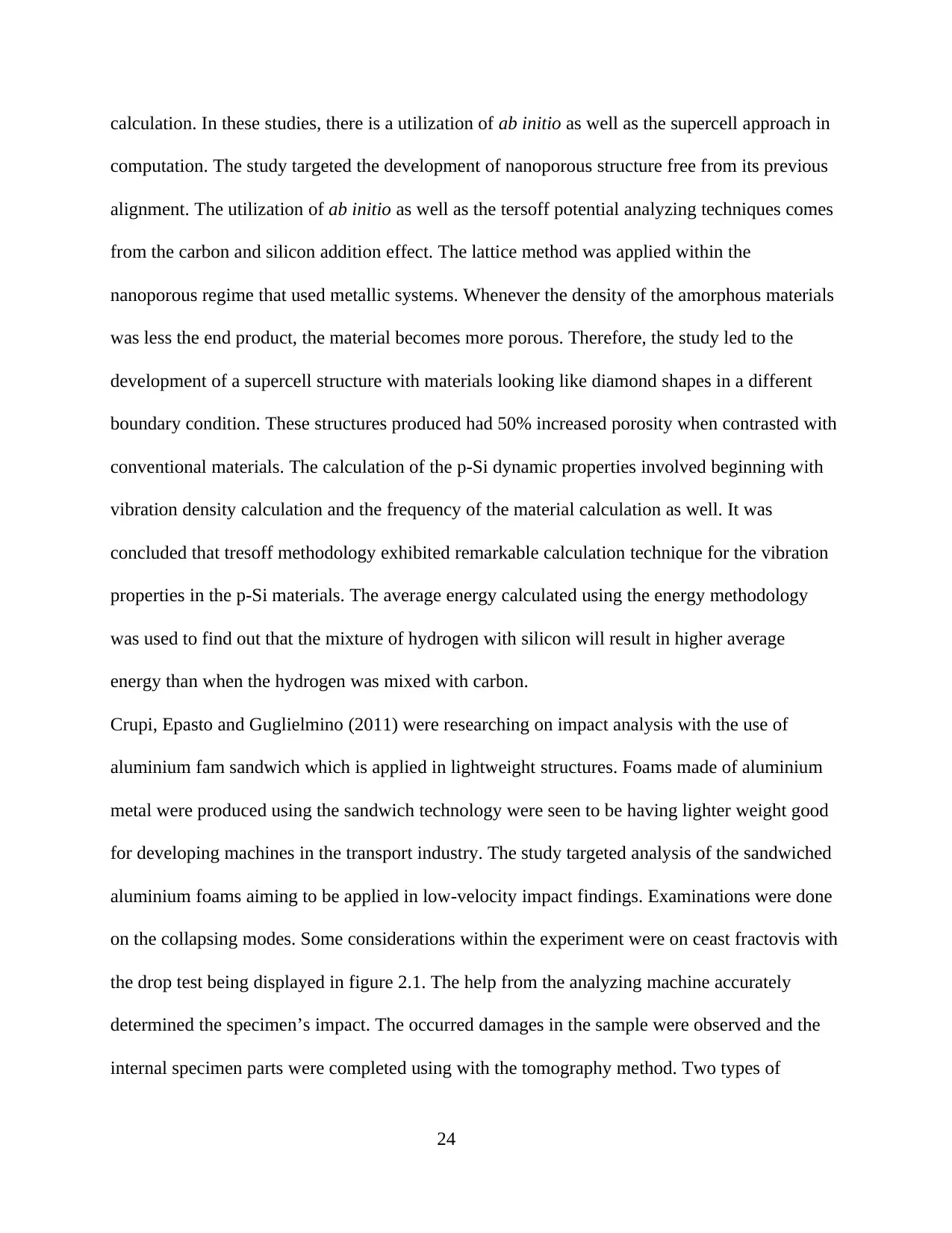
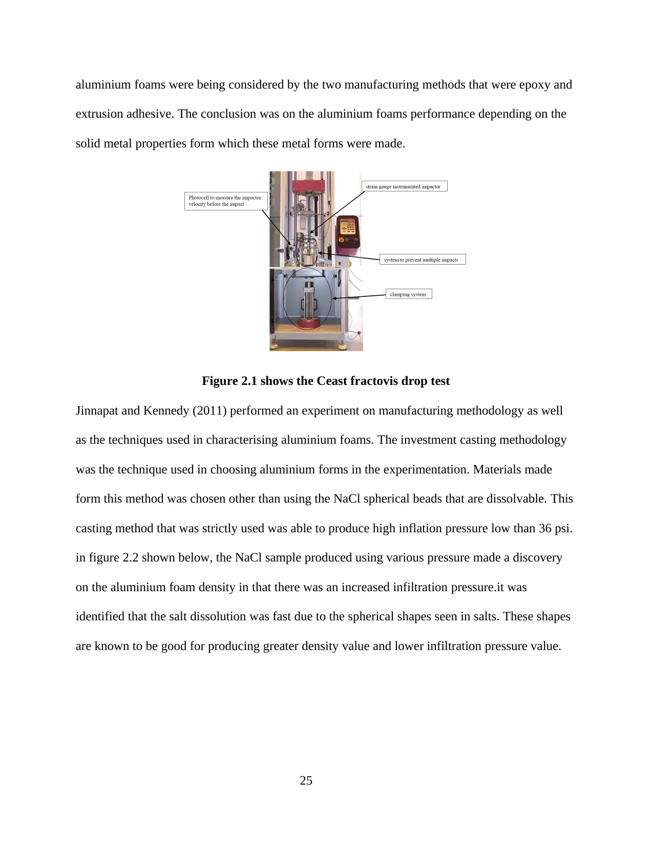
on the collapsing modes. Some considerations within the experiment were on ceast fractovis with
the drop test being displayed in figure 2.1. The help from the analyzing machine accurately
determined the specimen’s impact. The occurred damages in the sample were observed and the
internal specimen parts were completed using with the tomography method. Two types of
24
aluminium foams were being considered by the two manufacturing methods that were epoxy and
extrusion adhesive. The conclusion was on the aluminium foams performance depending on the
solid metal properties form which these metal forms were made.
Figure 2.1 shows the Ceast fractovis drop test
Jinnapat and Kennedy (2011) performed an experiment on manufacturing methodology as well
as the techniques used in characterising aluminium foams. The investment casting methodology
was the technique used in choosing aluminium forms in the experimentation. Materials made
form this method was chosen other than using the NaCl spherical beads that are dissolvable. This
casting method that was strictly used was able to produce high inflation pressure low than 36 psi.
in figure 2.2 shown below, the NaCl sample produced using various pressure made a discovery
on the aluminium foam density in that there was an increased infiltration pressure.it was
identified that the salt dissolution was fast due to the spherical shapes seen in salts. These shapes
are known to be good for producing greater density value and lower infiltration pressure value.
25
Paraphrase This Document
Need a fresh take? Get an instant paraphrase of this document with our AI Paraphraser
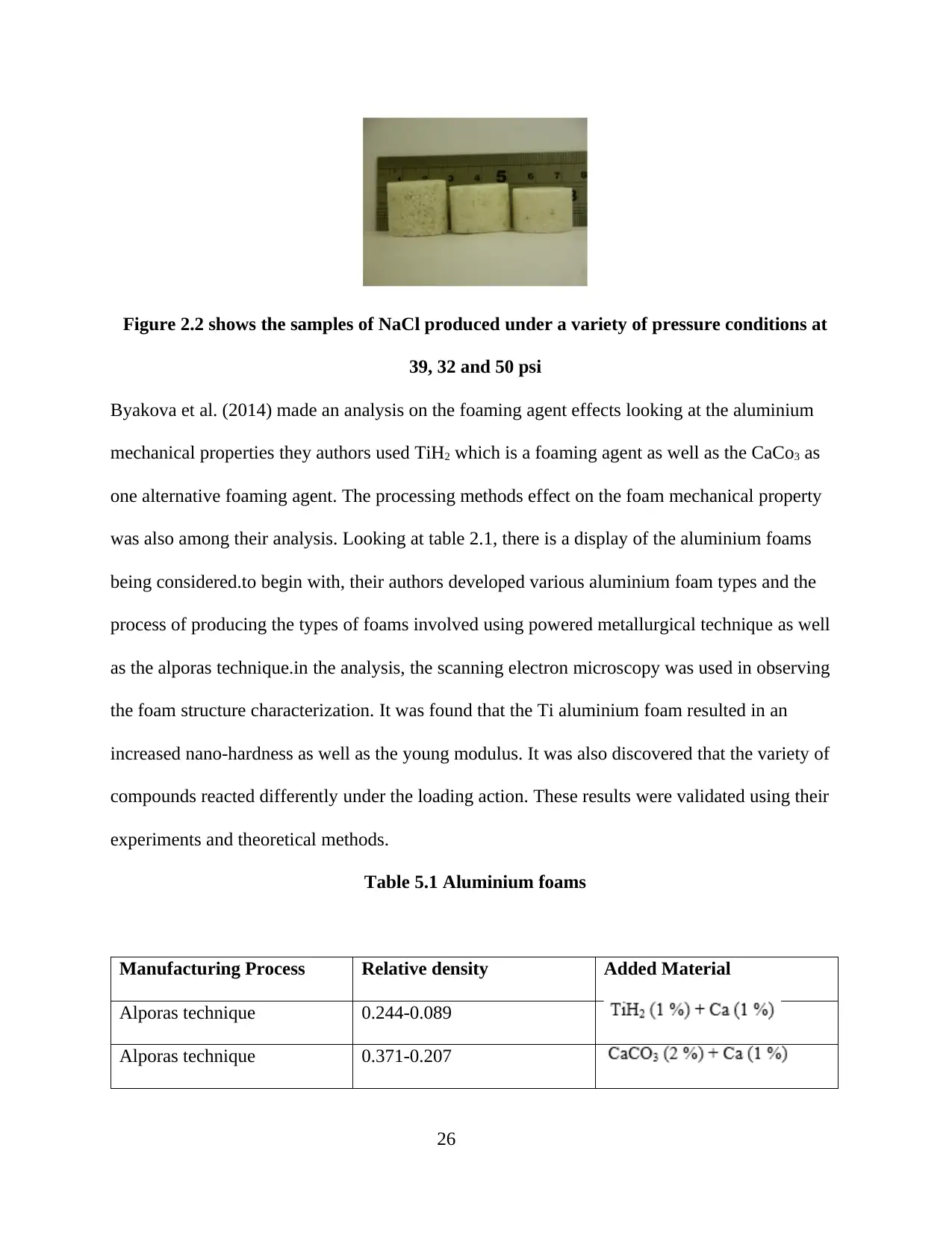
Figure 2.2 shows the samples of NaCl produced under a variety of pressure conditions at
39, 32 and 50 psi
Byakova et al. (2014) made an analysis on the foaming agent effects looking at the aluminium
mechanical properties they authors used TiH2 which is a foaming agent as well as the CaCo3 as
one alternative foaming agent. The processing methods effect on the foam mechanical property
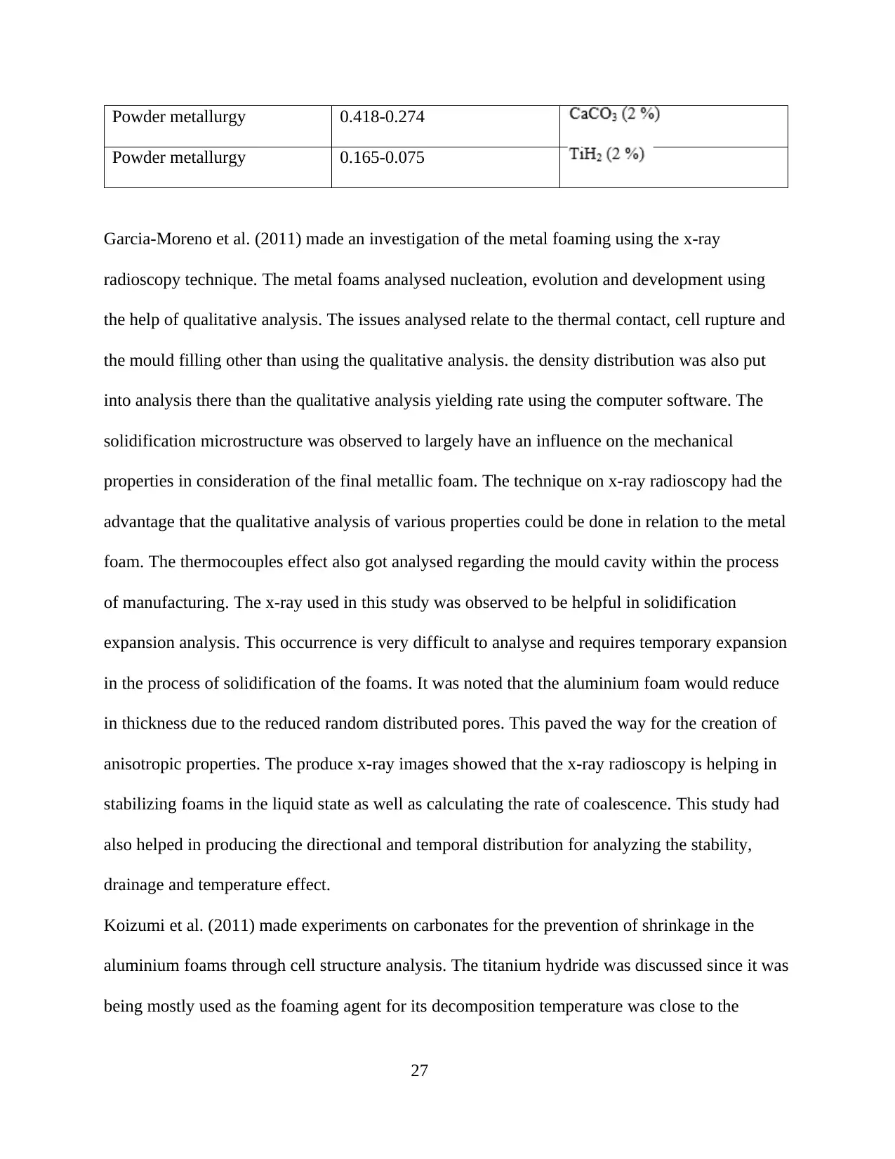
was also among their analysis. Looking at table 2.1, there is a display of the aluminium foams
being considered.to begin with, their authors developed various aluminium foam types and the
process of producing the types of foams involved using powered metallurgical technique as well
as the alporas technique.in the analysis, the scanning electron microscopy was used in observing
the foam structure characterization. It was found that the Ti aluminium foam resulted in an
increased nano-hardness as well as the young modulus. It was also discovered that the variety of
compounds reacted differently under the loading action. These results were validated using their
experiments and theoretical methods.
Table 5.1 Aluminium foams
Manufacturing Process Relative density Added Material
Alporas technique 0.244-0.089
Alporas technique 0.371-0.207
26
Powder metallurgy 0.418-0.274
Powder metallurgy 0.165-0.075
Garcia-Moreno et al. (2011) made an investigation of the metal foaming using the x-ray
radioscopy technique. The metal foams analysed nucleation, evolution and development using
the help of qualitative analysis. The issues analysed relate to the thermal contact, cell rupture and
the mould filling other than using the qualitative analysis. the density distribution was also put
into analysis there than the qualitative analysis yielding rate using the computer software. The
solidification microstructure was observed to largely have an influence on the mechanical
properties in consideration of the final metallic foam. The technique on x-ray radioscopy had the
advantage that the qualitative analysis of various properties could be done in relation to the metal
foam. The thermocouples effect also got analysed regarding the mould cavity within the process
of manufacturing. The x-ray used in this study was observed to be helpful in solidification
expansion analysis. This occurrence is very difficult to analyse and requires temporary expansion
in the process of solidification of the foams. It was noted that the aluminium foam would reduce
in thickness due to the reduced random distributed pores. This paved the way for the creation of
anisotropic properties. The produce x-ray images showed that the x-ray radioscopy is helping in
stabilizing foams in the liquid state as well as calculating the rate of coalescence. This study had
also helped in producing the directional and temporal distribution for analyzing the stability,
drainage and temperature effect.
Koizumi et al. (2011) made experiments on carbonates for the prevention of shrinkage in the
aluminium foams through cell structure analysis. The titanium hydride was discussed since it was
being mostly used as the foaming agent for its decomposition temperature was close to the
27
aluminium alloy melting point’s temperature. The titanium hydride was also observed to be
expensive and people may opt to use carbonate in foaming agents for titanium. The prevention of
shrinkage was done using cell connection as well as cell structure due to the oxidized cell
stability. When the magnesium carbonate was added the dolomite decomposition became faster
thereby facilitating the prevention of shrinkage. Adding the dolomite in multiple sense ed t the
result being made of fine cell structures with a 0.87 density. However, it shows that the non-
homogeneity structure of cells had low-density values.
Vesenjak et al. (2012) made an analysis of the metallic foam behaviour under the impact loading
as well as the action shock loading. The study was targeting the material as well as the structural
calculation for the metallic foams in the open-cell aluminium foams. Experiments and the
dynamic simulations were conducted using the computers to observe the aluminium foams
restricted in tanks. The tans were filled using water before being exposed to explosive charges.
The considered tank was sizing up to 200 by 200 by 135 mm3 using the PMMA walls for seeing
the shock waves. The shadowgraph taken into consideration involve the methods to develop
shock waves and the effect on the aluminium foams. The LS-DYNA was used in performing the
numerical study explicitly via the finite element software. Three distinct models were considered
for producing various aluminium foams before validation through experimental results.
Zhang and Olin (2014) had to analyse various works to come up with the experimental results on
porous gold foam. The synthesis of the foam was being done using a number of methods such as
self-assembly, spray, de-alloying and electrochemical disposition. The porous gold was analysed
and defined using its roughness and the two-surfaces’ areas. It was discovered that the porous
gold’s roughness was 1000 if produced using electrochemical deposition between NaBH4 as well
as KCl, while their roughness reads 218 when produced using electrochemical deposition
28
Secure Best Marks with AI Grader
Need help grading? Try our AI Grader for instant feedback on your assignments.
between Cl as well as Au. It was discovered that the porous fold foam was being used in the
production of electrochemical and biological sensors due to their existing chemical stability, high
conductivity, easier modification and greater surface area to volume ratio. The foams are as well
being used in the production of solar cells due to their high conductivity and transparent
property. The porous gold foam is also being utilized in the detection of DNA other than
bacteria. The foam has other uses such as being used as energy storage other thane being used in
making supercapacitors that are consisting of graphene combination of materials.
Billiet et al. (2015) made an analysis of the radiative and orientation transfer of heat when using
aluminium foams with induced buoyancy convection. The study observed the aluminium foam in
its fine heat sink formation. The heat sink’s dimension that was used by these authors was
identical in every case. The foam that was first considered by the authors was produced using the
investment casting methodology with a 00946 porosity and a 10 pore per inch density. The next
foam structure was produced using solvable core casting methodology with a 0.85 porosity as
well as a 2.5 pore per inch density. These heat sinks were analysed using two varying
orientations (vertical as well as horizontal). The heat flux of the heat sinks was determined for
the cases being checked for performance in every case. It was found out that the difference in
temperature was more than 300 C in heat sinks produced and lacked aluminium foams
performing better compared to the heat sinks made of aluminium foams. The experimentation
conduction had fixed temperatures of the ambient heat sink between 10 to 700 C. once through
the setting the temperature, the PID was used in controlling the averaged temperature of the heat
sink’s base plate. It was discovered that the emitted power through temperature measurement
between the ambient air and the base plate, was measured in heat dissipation and managed to be
reaching a steady state temperature. The heat dissipated was measured to be the thermal
29
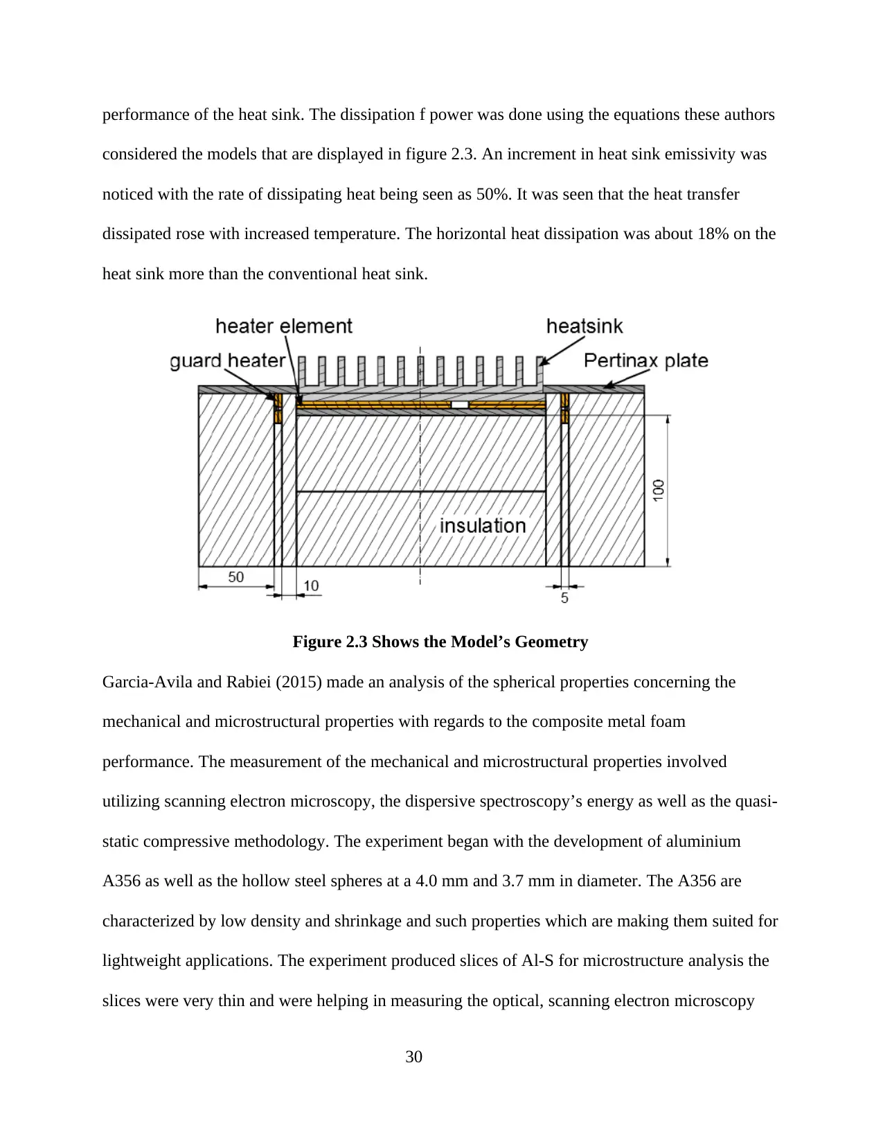
performance of the heat sink. The dissipation f power was done using the equations these authors
considered the models that are displayed in figure 2.3. An increment in heat sink emissivity was
noticed with the rate of dissipating heat being seen as 50%. It was seen that the heat transfer
dissipated rose with increased temperature. The horizontal heat dissipation was about 18% on the
heat sink more than the conventional heat sink.
Figure 2.3 Shows the Model’s Geometry
Garcia-Avila and Rabiei (2015) made an analysis of the spherical properties concerning the
mechanical and microstructural properties with regards to the composite metal foam
performance. The measurement of the mechanical and microstructural properties involved
utilizing scanning electron microscopy, the dispersive spectroscopy’s energy as well as the quasi-
static compressive methodology. The experiment began with the development of aluminium
A356 as well as the hollow steel spheres at a 4.0 mm and 3.7 mm in diameter. The A356 are
characterized by low density and shrinkage and such properties which are making them suited for
lightweight applications. The experiment produced slices of Al-S for microstructure analysis the
slices were very thin and were helping in measuring the optical, scanning electron microscopy
30
and digital techniques. There were additional rectangular samples for conducting the mechanical
test. The scanning electron microscopy produced images good for measuring surface roughness
using the Taylor Hobson surface profilometer. The foam’s density was determined using the
scanning electron microscopy imagery as well as the J. v1.43u images software. The measured
surface roughness by the authors is seen in table 2.2. There were four tests that had been
conducted on every hollowed sphere with 4.0 mm and 3.7 mm diameters.
Table 2.2 Shows the Surface roughness
The diameter of the sphere Average roughness Roughness
3.7 mm
4.558 μm
2.944 μm
2.971 μm
8.418 μm
3.897 μm
4.0 mm 5.716 μm 6.516 μm
5.144 μm
5.831 μm
5.329 μm
Güner, Arıkan and Nebioglu (2015) made development on a new technique used in the
production of aluminium foam with the casting method technology. The metal foam’s effect was
discussed with regards to the casting method over various methods, the metals had low resistance
to corrosion and low thermal conductivity. The produced metal foams were able to help in
develop metal casts very applicable in aerospace and automotive applications. The metal foams
being developed using the cast metal methodology have high stiffness, fracture resistance, flame
31
Paraphrase This Document
Need a fresh take? Get an instant paraphrase of this document with our AI Paraphraser
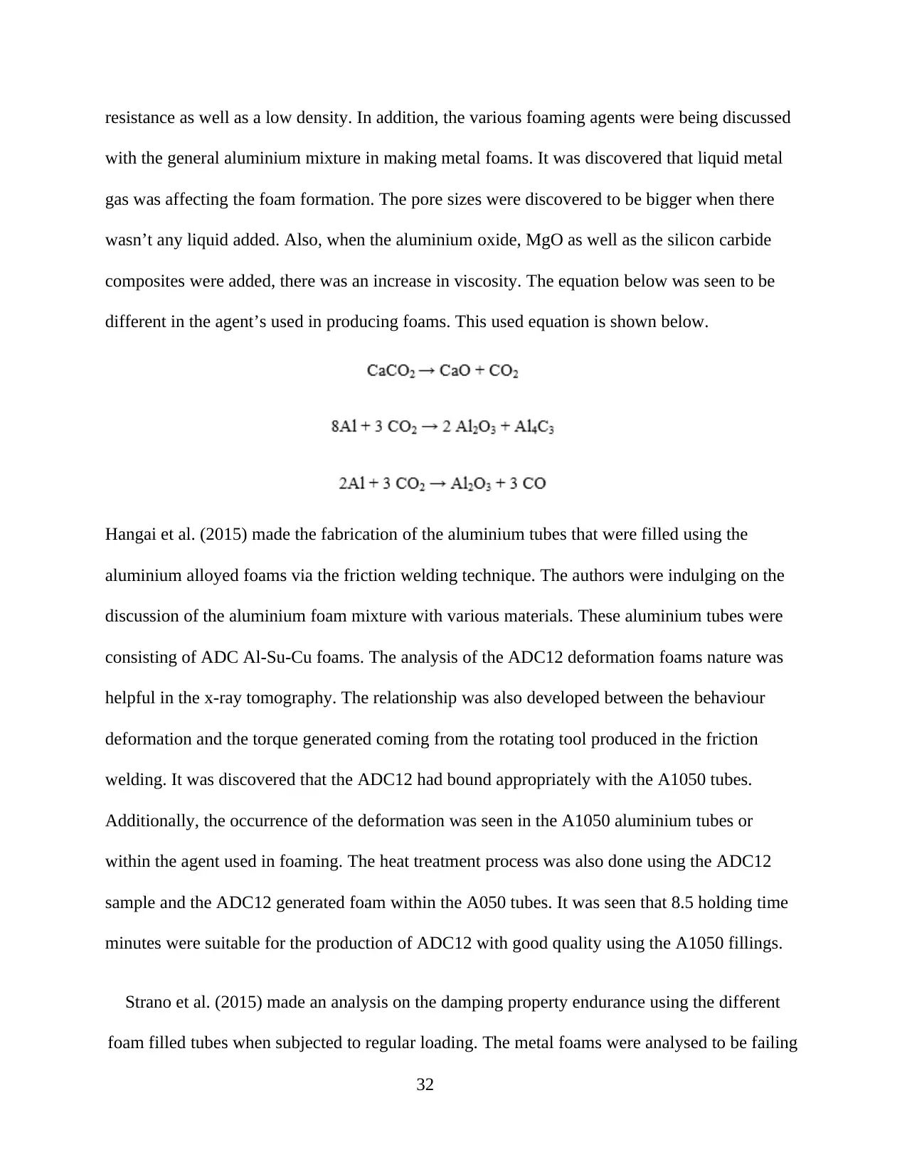
resistance as well as a low density. In addition, the various foaming agents were being discussed
with the general aluminium mixture in making metal foams. It was discovered that liquid metal
gas was affecting the foam formation. The pore sizes were discovered to be bigger when there
wasn’t any liquid added. Also, when the aluminium oxide, MgO as well as the silicon carbide
composites were added, there was an increase in viscosity. The equation below was seen to be
different in the agent’s used in producing foams. This used equation is shown below.
Hangai et al. (2015) made the fabrication of the aluminium tubes that were filled using the
aluminium alloyed foams via the friction welding technique. The authors were indulging on the
discussion of the aluminium foam mixture with various materials. These aluminium tubes were
consisting of ADC Al-Su-Cu foams. The analysis of the ADC12 deformation foams nature was
helpful in the x-ray tomography. The relationship was also developed between the behaviour
deformation and the torque generated coming from the rotating tool produced in the friction
welding. It was discovered that the ADC12 had bound appropriately with the A1050 tubes.
Additionally, the occurrence of the deformation was seen in the A1050 aluminium tubes or
within the agent used in foaming. The heat treatment process was also done using the ADC12
sample and the ADC12 generated foam within the A050 tubes. It was seen that 8.5 holding time
minutes were suitable for the production of ADC12 with good quality using the A1050 fillings.
Strano et al. (2015) made an analysis on the damping property endurance using the different
foam filled tubes when subjected to regular loading. The metal foams were analysed to be failing
32
when kept under conditions having cyclic loading. It was discussed that the outer case foams
helped in increasing the stiffness and strength of the material while giving the foam metals the
core help in adding the energy absorbing property. Two distinct foams were used in this
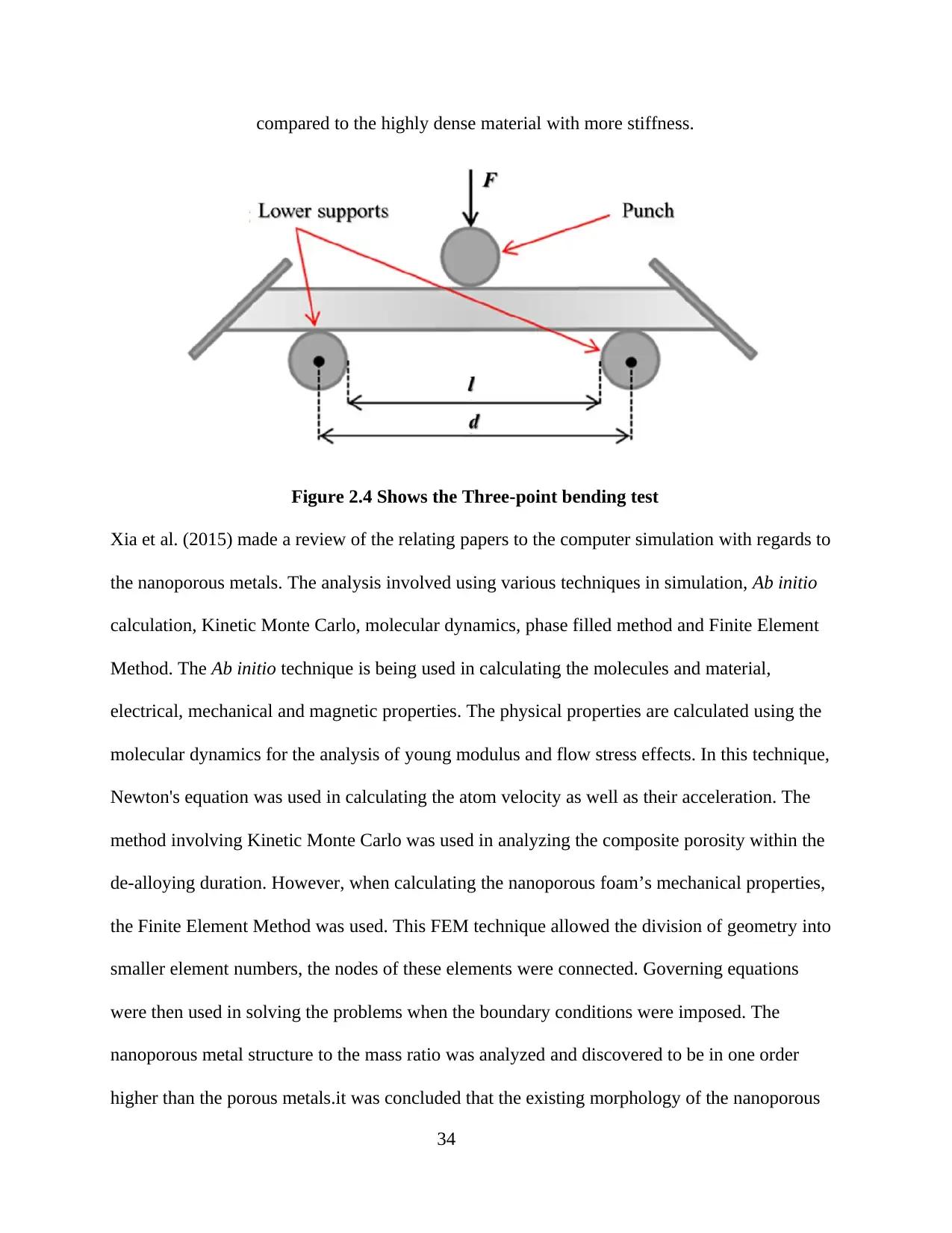
experiment with a 600 Kg/m3 and 470 Kg/m3 thermal conductivity. The three-point bending test
was used in analysing the effect that the cycle number impose. Figure 2.4 displays the bending
test’s schematic representation. The load increased by 2kN for every addition of 1000 cycle
number and this concluded the highest load the specimen could withstand. A modal analysis was
also conducted for analyzing the mode of vibration these tests were conducted after as well as
before the cyclic tests. There were two modes used in the experiment which were labelled 700
Hz and 90 Hz. The finite element analysis was also conducted and the experiment validated
using this technique. In the use of the FEM technique, an additional ABAQUS software was used
in finding the 4000 MPa elasticity modulus for the foams with low density and a 6400 MPa
elasticity modulus for the foams with higher density. It was seen that when the ratios were
damped in every case analysed, there was an increased frictional work as well as hysteresis. This
interfacial result was found to be in foam with high density which could not affect the damping
ratio whereas the interfacial ratio was seen to be heavily affecting the value of the damping ratio.
It was also noticed that the less dense materials had a uniform stiffness with respect to time
33
compared to the highly dense material with more stiffness.
Figure 2.4 Shows the Three-point bending test
Xia et al. (2015) made a review of the relating papers to the computer simulation with regards to
the nanoporous metals. The analysis involved using various techniques in simulation, Ab initio
calculation, Kinetic Monte Carlo, molecular dynamics, phase filled method and Finite Element
Method. The Ab initio technique is being used in calculating the molecules and material,
electrical, mechanical and magnetic properties. The physical properties are calculated using the
molecular dynamics for the analysis of young modulus and flow stress effects. In this technique,
Newton's equation was used in calculating the atom velocity as well as their acceleration. The
method involving Kinetic Monte Carlo was used in analyzing the composite porosity within the
de-alloying duration. However, when calculating the nanoporous foam’s mechanical properties,
the Finite Element Method was used. This FEM technique allowed the division of geometry into
smaller element numbers, the nodes of these elements were connected. Governing equations
were then used in solving the problems when the boundary conditions were imposed. The
nanoporous metal structure to the mass ratio was analyzed and discovered to be in one order
higher than the porous metals.it was concluded that the existing morphology of the nanoporous
34
Secure Best Marks with AI Grader
Need help grading? Try our AI Grader for instant feedback on your assignments.
Kinetic Monte Carlo structure was best. Therefore, better analysis of the annealing,
microstructure and plastic deformation evolution using the molecular dynamics and Kinetic
Monte Carlo were the best techniques to use.
Depczynski et al. (2016) made a modelling and microstructural characterisation analysis on the
sintered metals with porous features. The study was aimed at getting the iron powder materials
ASC 100.29 as well as the sDistaloy SE. ASC 100.29 atomization process on that the distaloy
was reduced from sponge-iron. There was a production of efficient and low-cost methodology
foam for the production of metals. The foams were generated and tested through the sintering
process of the ammonia atmosphere. It was a discussion that the range of porosity was depending
on the type of material and the size of particles. The discussion also indulged in examining the
dependency of the porosity on the material solid foam used in producing oxide powder. The
Brunauer Emmett Teller model was used in this experiment for the analysis of the type and
porosity. In addition, the scanning electron microscopy was used in analyzing the ASC 100.29
digital images as well as the Distalov. The sieve analysis was conducted for the determination of
the grain size by the percentage of the ASC 100.29. It was a consideration of the random particle
sizes as well as the distribution with an assumption that the particle sizes were known.
Duarte and Ferreira (2016) produced an analysis of the nanocomposites and the composite metal
foams. The study targeted the enhancement of mechanical properties using various nano size and
micro size particles. There as a reinforcement of the nano and microparticle sizes with closed
cells as well as open the cells of metallic foams. The discussion was that reinforcing the ceramic
particles helped in the prevention of coalescence and drainage, this led to saving the metal foams
from exhibiting non-uniform structures. The ceramic particle discussion helped in the
achievement of stability in a faster manner. The discussion also indulged in the particles made of
35
silicon carbide to reduce the drainage with the comparison of the aluminium particles it was also
a discussion that the addition of more particles of silicon carbide reduced drainage. The silicon
carbide particles improved the viscosity that was advantageous in adding the linear expansivity.
There was an added capability of the farms' brittleness using silicon carbide particles. It was
discussed that TiB2 particles improved the expansion of foams but led to the reduction of the
long-time stability. Table 2.3 shown below displays the comparison of the composite foam and
the conventional foam
Table 2.3 Shows the Conventional Foam Comparison with the Composite foam
Property
Composite foam Conventional foam
SS foam Carbon
Foam
Al-SS cast
foam
Al-LC cast
foam
Al-foam Al-foam
Relative
Density
(%)
37.5 38.9 42.5 42.5 8.9 14.8
Density
(gm/cm3)
2.95 3.06 2.45 2.43 0.24 0.4
Energy
absorption
(MJ/m3)
67.8 18.9 31 31 1.32 2.6
Diameter
(mm)
2.0 3.7 3.7 3.7 3 3
36
Thickness
(mm)
0.1 0.2 105 60 2.5 5
Stress
(MPa)
127 36.2 105 60 - -
Schampheleire et al. (2016) produced experimentation as well as numerical analysis of the metal
foam applications within the thermal industries. These numerical analyses were the visualizing
techniques applied in the Computational Fluid Dynamics methods. The CFD methodologies were
used in visualizing the small particle flow within the systems. CFD was used dealing with the
Finite Volume Method that solves the physical problem. The solution that uses CFD involves the
consideration of governing equations as well as the boundary conditions that are best used in
related problems. The models a basically three, FEM, FVM and FDM. The FDM has the easiest
technique and is mostly utilized in academics. On the other hand, the FVM and the FEM
methodologies are considered during an experiment with nodes, these techniques help give
solutions to the small elements while the FDM would be used in more discrete nodes. There are
discussions on the numerous factors belt to influence the answers gotten from the computational
fluid dynamics methods. For example the type of material, metal foam thickness, manufacturing
material method, rate of heat transfer to the surface area. Metal foam orientation, geometrical
parameters and (convection-free or forced convection) and the fouling effect. The Volume
Averaging Theory to the numerical simulation. The Navier-Strokes equation is used without the
heat generated term. This equation is made up of momentum conservation equation, mass
conservation equation and energy conservation equation. These equations are made of partial
differential equations that are first solved by one equation being converted to an algebraic form.
37
Paraphrase This Document
Need a fresh take? Get an instant paraphrase of this document with our AI Paraphraser
Sin this way, the Taylor expansion series as used. The calculation of the system’s performance
involved the calculation of the Number of Transfer Units. Its definition is the coefficient of heat
transferred multiplied by the surface area, averaged, before being divided the system’s heat
capacity. In the end, the authors managed to validate their experimental results.
Sreenivasa and Shivakumar (2018) made a review study on aluminium foam production. The
authors discussed the aluminium metal foam for the industries using lightweight materials. The
authors discussed the two methods used in the production of aluminium metal foams in liquid
form or the powder form. In producing the metallic foams, two methods were used; the blowing
agents and the gas injection foaming melts. There was an added discussion on the various
methods used in producing metallic foams. The limitations and the advantages were discussed
with regards to the metallic methods which include the dependency on applying the final metal
foam produced which allowed one selection of the method used in manufacturing. It was
concluded that the powder metallurgy could be producing metallic foams that are suited for
mechanical applications given that the powder metallurgy produced very high connectivity
within the metallic foams.
Huang et al. (2018) perfpomed their study on developing the new models that optimised the
mechanical as well as thermal performacne of the partioning cement walls. There was an
optimisation of transportation and construction performance with the use of metallic foams these
foams wwee made of cylindrical elliptic cavities that were used in forming partiton wall
porosity. In additon the authors managed to conduct numerical studies for the evaluation of
cement partion walls’ mechanical and thermal performance. The FEM technology was used in
this numerical study. Along the experiment’s procedure, the FEM was using the boundary
consition types that include unifrom displacement, squeezing force between patitioned walls and
38
force and bending force within hanging conditons. The FEM was cosidered in ABAQUS
software for the purpose of producing accurate results in the study of load and stress applications.
It was discovered that the control of eccentricity within the elliptic cavities made in cylinder
forms, the specimen’s stiffness could be altered for getting high quality performance with regards
to the thermal property. In additoin, the authors produced an analysis was done on the impact
loading effect on the specimen. The effect on the enrgy equqtion was solved and analysed with
reagrds to the specimen’s inne rtemperature. This experiment was cosidering the unsteady state
of the heat conduction equation in three dimensions.
39
CHAPTER III: METHODOLOGY
Various mathematical models must be put into account when analyzing the foams consisting of
metal composites. The mathematical models comprise of structural, mechanical and thermal
calculation features of various foams comprising of metals composites. Aluminium oxide, silicon
carbide, aluminium and boron carbide are among the most preferred foams containing metals
composites. A number of mathematical models should be put into consideration while calculating
specific heat, density, thermal conductivity, coefficient of thermal expansion and thermal
diffusivity. Three models are put into the account in respect with calculating thermal
conductivity, including, Hamilton and Crosser model, the rule of the physical mixture and
Maxwell model. The rule of the physical mixture is applied in the calculation of thermal
diffusivity, density, coefficient of thermal expansion and specific heat. Additionally, in
calculating thermal conductivity metal foam and the base metal's density are put into
consideration.
A number of mechanical features including hardness, elasticity, strain and compressive strengths
are calculated in regards to the metal foam and the metal base density for the closed type of cell
foams and open types of cell foams. Metal foam properties rely on the cell types, for instance,
closed or open. Anisotropy, defects, shapes and sizes of the materials are among the factors that
have impacts on the features of metal foams. In differentiating the features of materials that are
solid and metal foams, features of metal foams do not have subscripts whilst features of
solidified materials are presented with subscripts ‘s’, for instance, ρ and ρS respectively. The table
below outlines the various calculation formulas for metal foams and features of metal foams.
40
Secure Best Marks with AI Grader
Need help grading? Try our AI Grader for instant feedback on your assignments.
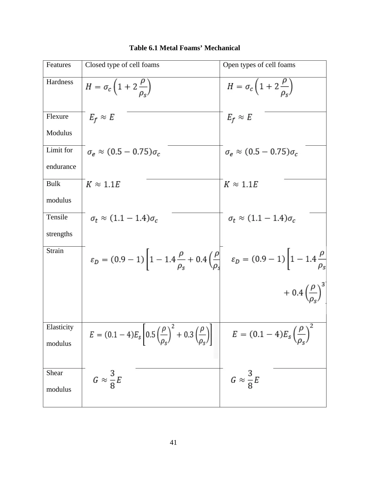
Table 6.1 Metal Foams’ Mechanical
Features Closed type of cell foams Open types of cell foams
Hardness
Flexure
Modulus
Limit for
endurance
Bulk
modulus
Tensile
strengths
Strain
Elasticity
modulus
Shear
modulus
41
Features Closed type of cell foams Open types of cell foams
Hardness
Flexure
Modulus
Limit for
endurance
Bulk
modulus
Tensile
strengths
Strain
Elasticity
modulus
Shear
modulus
41
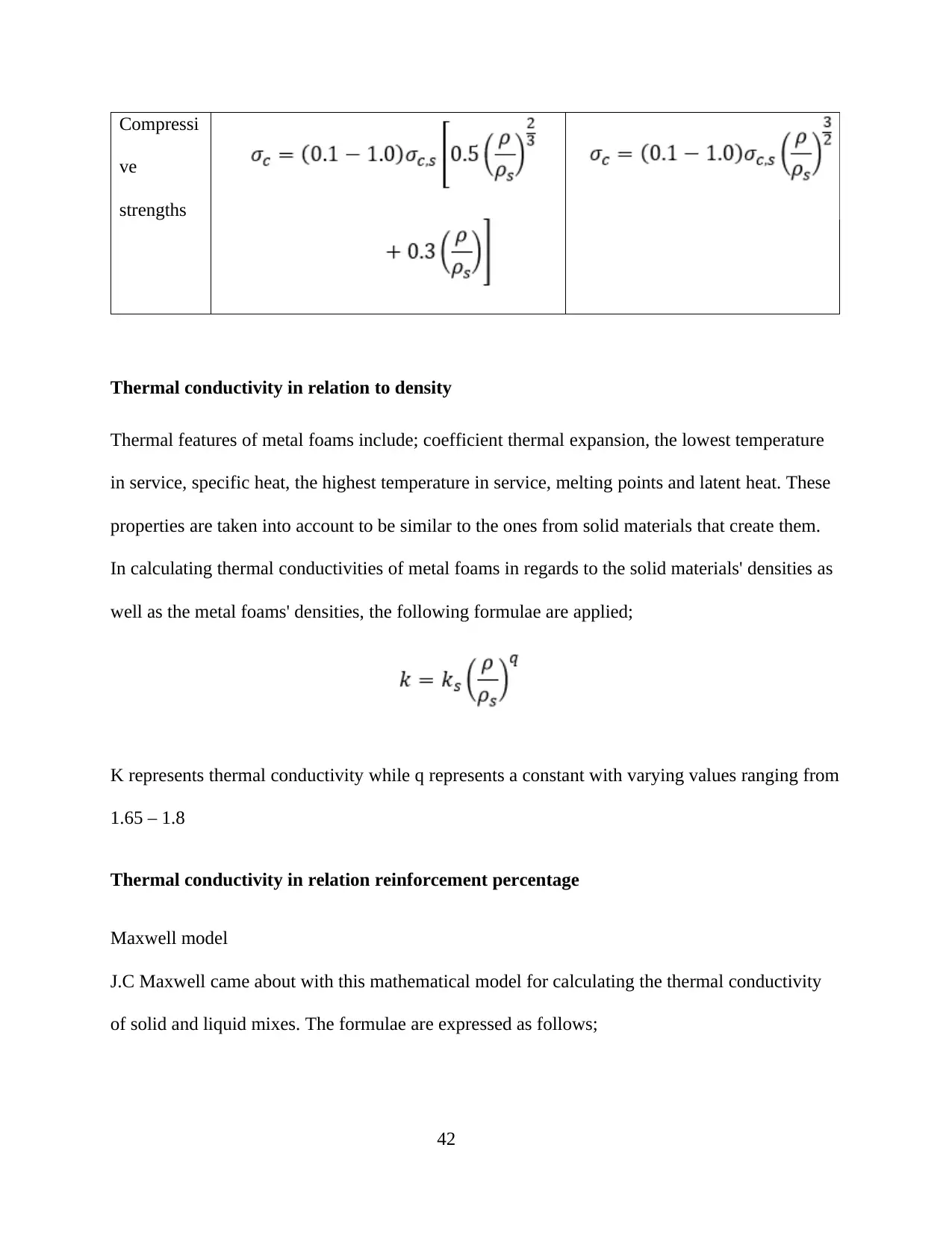
Compressi
ve
strengths
Thermal conductivity in relation to density
Thermal features of metal foams include; coefficient thermal expansion, the lowest temperature
in service, specific heat, the highest temperature in service, melting points and latent heat. These
properties are taken into account to be similar to the ones from solid materials that create them.
In calculating thermal conductivities of metal foams in regards to the solid materials' densities as
well as the metal foams' densities, the following formulae are applied;
K represents thermal conductivity while q represents a constant with varying values ranging from
1.65 – 1.8
Thermal conductivity in relation reinforcement percentage
Maxwell model
J.C Maxwell came about with this mathematical model for calculating the thermal conductivity
of solid and liquid mixes. The formulae are expressed as follows;
42
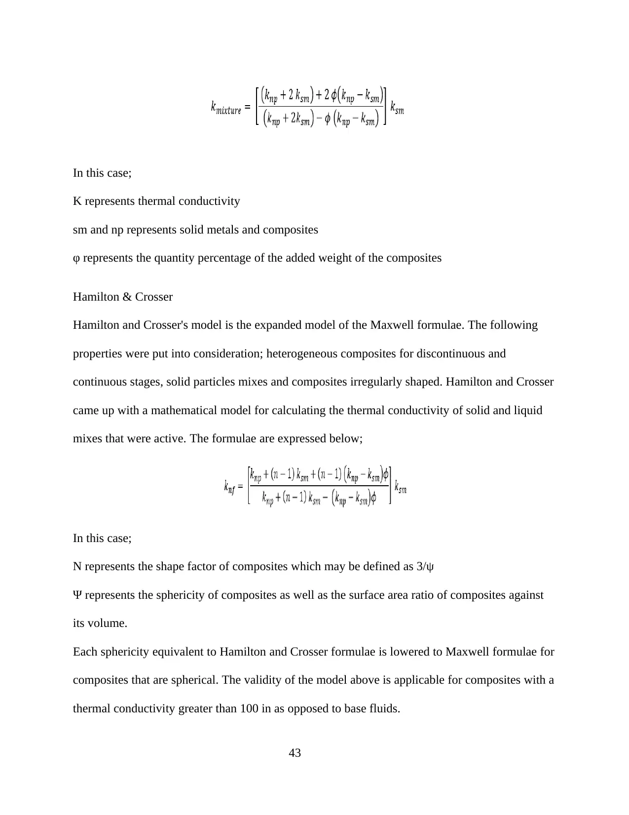
In this case;
K represents thermal conductivity
sm and np represents solid metals and composites
φ represents the quantity percentage of the added weight of the composites
Hamilton & Crosser
Hamilton and Crosser's model is the expanded model of the Maxwell formulae. The following
properties were put into consideration; heterogeneous composites for discontinuous and
continuous stages, solid particles mixes and composites irregularly shaped. Hamilton and Crosser
came up with a mathematical model for calculating the thermal conductivity of solid and liquid
mixes that were active. The formulae are expressed below;
In this case;
N represents the shape factor of composites which may be defined as 3/ψ
Ψ represents the sphericity of composites as well as the surface area ratio of composites against
its volume.
Each sphericity equivalent to Hamilton and Crosser formulae is lowered to Maxwell formulae for
composites that are spherical. The validity of the model above is applicable for composites with a
thermal conductivity greater than 100 in as opposed to base fluids.
43
Paraphrase This Document
Need a fresh take? Get an instant paraphrase of this document with our AI Paraphraser
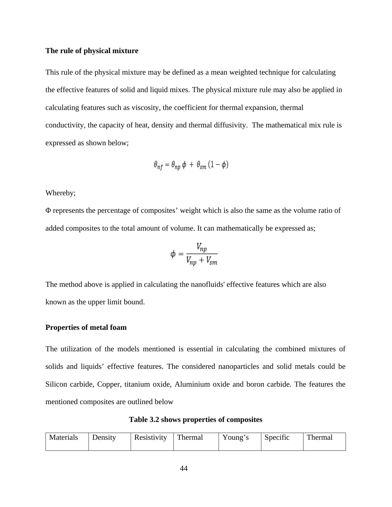
The rule of physical mixture
This rule of the physical mixture may be defined as a mean weighted technique for calculating
the effective features of solid and liquid mixes. The physical mixture rule may also be applied in
calculating features such as viscosity, the coefficient for thermal expansion, thermal
conductivity, the capacity of heat, density and thermal diffusivity. The mathematical mix rule is
expressed as shown below;
Whereby;
Φ represents the percentage of composites’ weight which is also the same as the volume ratio of
added composites to the total amount of volume. It can mathematically be expressed as;
The method above is applied in calculating the nanofluids' effective features which are also
known as the upper limit bound.
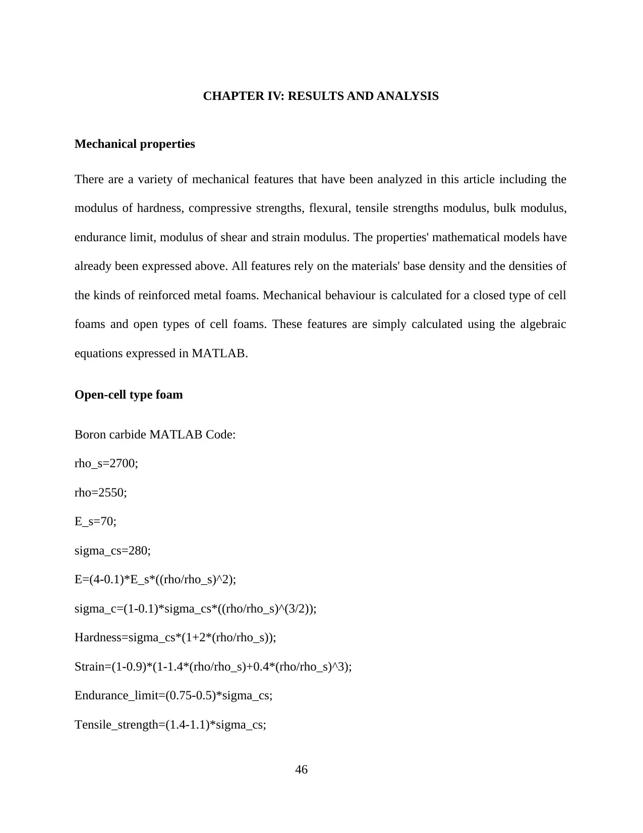
Properties of metal foam
The utilization of the models mentioned is essential in calculating the combined mixtures of
solids and liquids’ effective features. The considered nanoparticles and solid metals could be
Silicon carbide, Copper, titanium oxide, Aluminium oxide and boron carbide. The features the
mentioned composites are outlined below
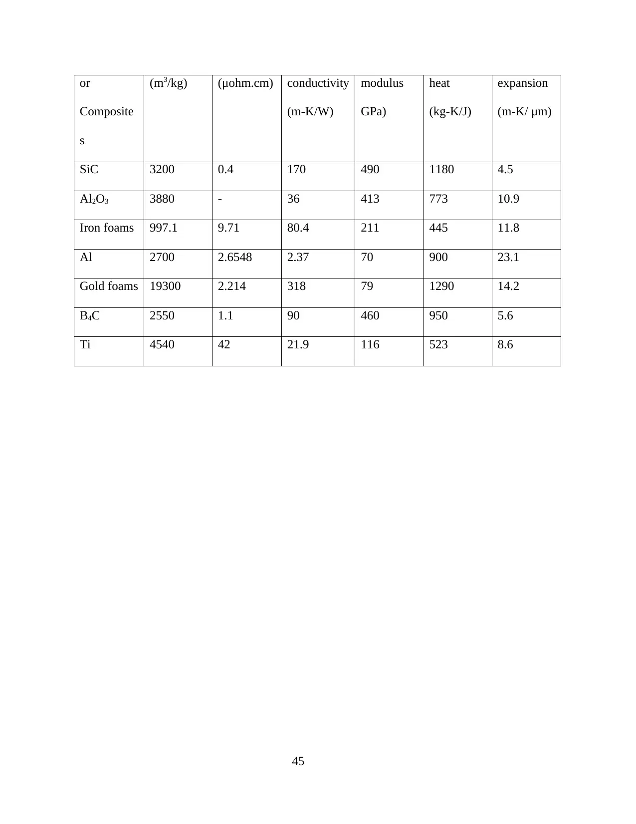
Table 3.2 shows properties of composites
Materials Density Resistivity Thermal Young’s Specific Thermal
44
or
Composite
s
(m3/kg) (μohm.cm) conductivity
(m-K/W)
modulus
GPa)
heat
(kg-K/J)
expansion
(m-K/ μm)
SiC 3200 0.4 170 490 1180 4.5
Al2O3 3880 - 36 413 773 10.9
Iron foams 997.1 9.71 80.4 211 445 11.8
Al 2700 2.6548 2.37 70 900 23.1
Gold foams 19300 2.214 318 79 1290 14.2
B4C 2550 1.1 90 460 950 5.6
Ti 4540 42 21.9 116 523 8.6
45
CHAPTER IV: RESULTS AND ANALYSIS
Mechanical properties
There are a variety of mechanical features that have been analyzed in this article including the
modulus of hardness, compressive strengths, flexural, tensile strengths modulus, bulk modulus,
endurance limit, modulus of shear and strain modulus. The properties' mathematical models have
already been expressed above. All features rely on the materials' base density and the densities of
the kinds of reinforced metal foams. Mechanical behaviour is calculated for a closed type of cell
foams and open types of cell foams. These features are simply calculated using the algebraic
equations expressed in MATLAB.
Open-cell type foam
Boron carbide MATLAB Code:
rho_s=2700;
rho=2550;
E_s=70;
sigma_cs=280;
E=(4-0.1)*E_s*((rho/rho_s)^2);
sigma_c=(1-0.1)*sigma_cs*((rho/rho_s)^(3/2));
Hardness=sigma_cs*(1+2*(rho/rho_s));
Strain=(1-0.9)*(1-1.4*(rho/rho_s)+0.4*(rho/rho_s)^3);
Endurance_limit=(0.75-0.5)*sigma_cs;
Tensile_strength=(1.4-1.1)*sigma_cs;
46
Secure Best Marks with AI Grader
Need help grading? Try our AI Grader for instant feedback on your assignments.
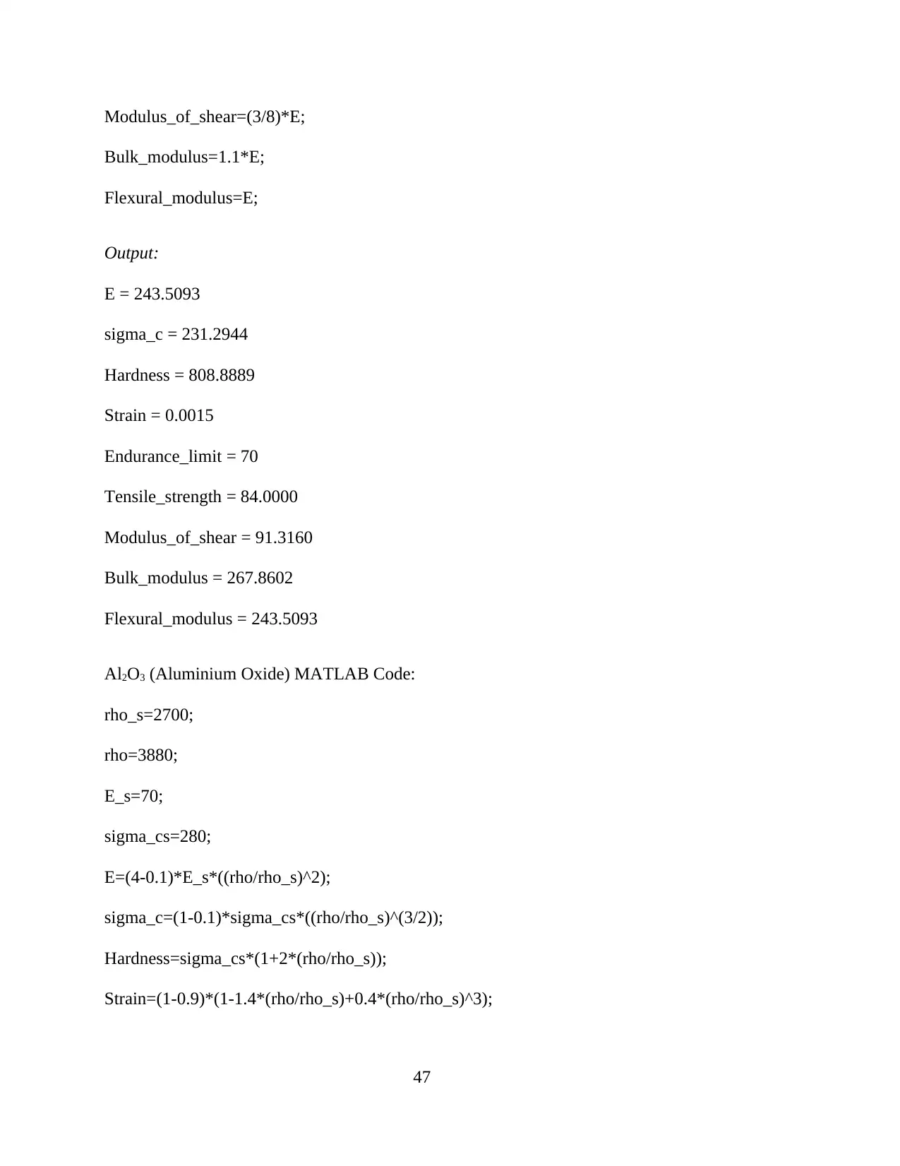
Modulus_of_shear=(3/8)*E;
Bulk_modulus=1.1*E;
Flexural_modulus=E;
Output:
E = 243.5093
sigma_c = 231.2944
Hardness = 808.8889
Strain = 0.0015
Endurance_limit = 70
Tensile_strength = 84.0000
Modulus_of_shear = 91.3160
Bulk_modulus = 267.8602
Flexural_modulus = 243.5093
Al2O3 (Aluminium Oxide) MATLAB Code:
rho_s=2700;
rho=3880;
E_s=70;
sigma_cs=280;
E=(4-0.1)*E_s*((rho/rho_s)^2);
sigma_c=(1-0.1)*sigma_cs*((rho/rho_s)^(3/2));
Hardness=sigma_cs*(1+2*(rho/rho_s));
Strain=(1-0.9)*(1-1.4*(rho/rho_s)+0.4*(rho/rho_s)^3);
47
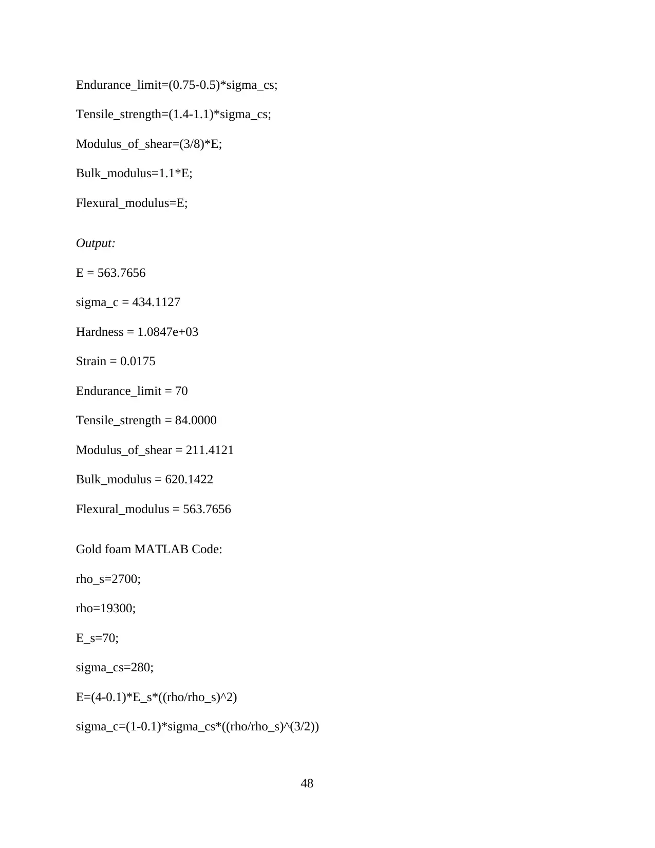
Endurance_limit=(0.75-0.5)*sigma_cs;
Tensile_strength=(1.4-1.1)*sigma_cs;
Modulus_of_shear=(3/8)*E;
Bulk_modulus=1.1*E;
Flexural_modulus=E;
Output:
E = 563.7656
sigma_c = 434.1127
Hardness = 1.0847e+03
Strain = 0.0175
Endurance_limit = 70
Tensile_strength = 84.0000
Modulus_of_shear = 211.4121
Bulk_modulus = 620.1422
Flexural_modulus = 563.7656
Gold foam MATLAB Code:
rho_s=2700;
rho=19300;
E_s=70;
sigma_cs=280;
E=(4-0.1)*E_s*((rho/rho_s)^2)
sigma_c=(1-0.1)*sigma_cs*((rho/rho_s)^(3/2))
48
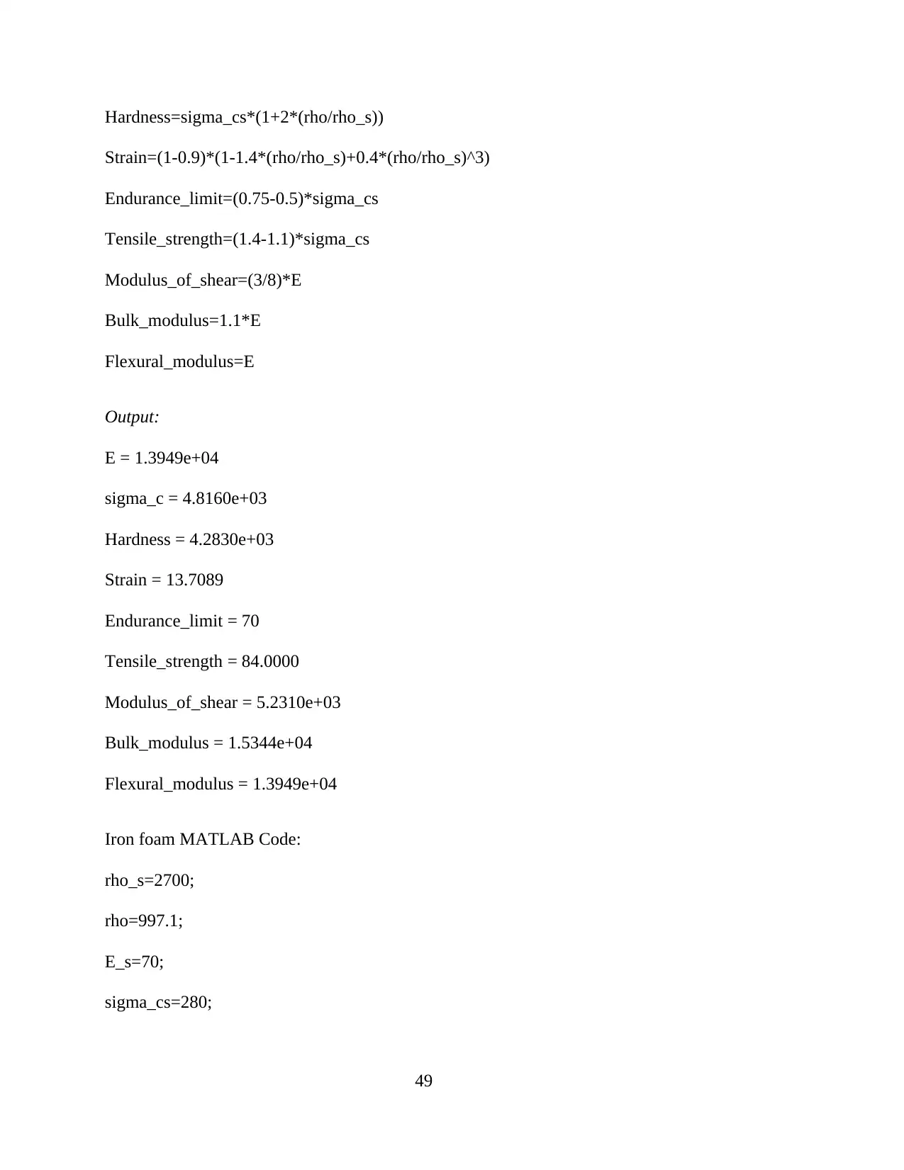
Hardness=sigma_cs*(1+2*(rho/rho_s))
Strain=(1-0.9)*(1-1.4*(rho/rho_s)+0.4*(rho/rho_s)^3)
Endurance_limit=(0.75-0.5)*sigma_cs
Tensile_strength=(1.4-1.1)*sigma_cs
Modulus_of_shear=(3/8)*E
Bulk_modulus=1.1*E
Flexural_modulus=E
Output:
E = 1.3949e+04
sigma_c = 4.8160e+03
Hardness = 4.2830e+03
Strain = 13.7089
Endurance_limit = 70
Tensile_strength = 84.0000
Modulus_of_shear = 5.2310e+03
Bulk_modulus = 1.5344e+04
Flexural_modulus = 1.3949e+04
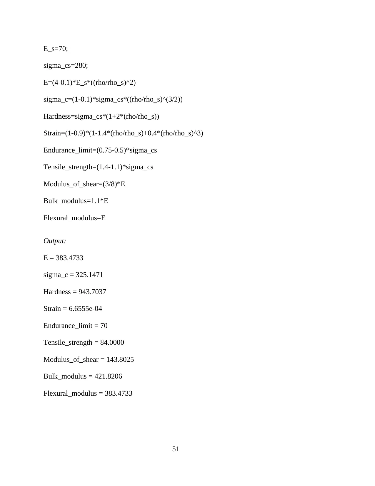
Iron foam MATLAB Code:
rho_s=2700;
rho=997.1;
E_s=70;
sigma_cs=280;
49
Paraphrase This Document
Need a fresh take? Get an instant paraphrase of this document with our AI Paraphraser

E=(4-0.1)*E_s*((rho/rho_s)^2)
sigma_c=(1-0.1)*sigma_cs*((rho/rho_s)^(3/2))
Hardness=sigma_cs*(1+2*(rho/rho_s))
Strain=(1-0.9)*(1-1.4*(rho/rho_s)+0.4*(rho/rho_s)^3)
Endurance_limit=(0.75-0.5)*sigma_cs
Tensile_strength=(1.4-1.1)*sigma_cs
Modulus_of_shear=(3/8)*E
Bulk_modulus=1.1*E
Flexural_modulus=E
Output:
E = 37.2317
sigma_c = 56.5540
Hardness = 486.8059
Strain = 0.0503
Endurance_limit = 70
Tensile_strength = 84.0000
Modulus_of_shear = 13.9619
Bulk_modulus = 40.9548
Flexural_modulus = 37.2317
Silicon carbide (SiC) foam MATLAB Code
rho_s=2700;
rho=3200;
50
E_s=70;
sigma_cs=280;
E=(4-0.1)*E_s*((rho/rho_s)^2)
sigma_c=(1-0.1)*sigma_cs*((rho/rho_s)^(3/2))
Hardness=sigma_cs*(1+2*(rho/rho_s))
Strain=(1-0.9)*(1-1.4*(rho/rho_s)+0.4*(rho/rho_s)^3)
Endurance_limit=(0.75-0.5)*sigma_cs
Tensile_strength=(1.4-1.1)*sigma_cs
Modulus_of_shear=(3/8)*E
Bulk_modulus=1.1*E
Flexural_modulus=E
Output:
E = 383.4733
sigma_c = 325.1471
Hardness = 943.7037
Strain = 6.6555e-04
Endurance_limit = 70
Tensile_strength = 84.0000
Modulus_of_shear = 143.8025
Bulk_modulus = 421.8206
Flexural_modulus = 383.4733
51

Titanium foam MATLAB Code
rho_s=2700;
rho=4540;
E_s=70;
sigma_cs=280;
E=(4-0.1)*E_s*((rho/rho_s)^2)
sigma_c=(1-0.1)*sigma_cs*((rho/rho_s)^(3/2))
Hardness=sigma_cs*(1+2*(rho/rho_s))
Strain=(1-0.9)*(1-1.4*(rho/rho_s)+0.4*(rho/rho_s)^3)
Endurance_limit=(0.75-0.5)*sigma_cs
Tensile_strength=(1.4-1.1)*sigma_cs
Modulus_of_shear=(3/8)*E
Bulk_modulus=1.1*E
Flexural_modulus=E
Output
E = 771.8747
sigma_c = 549.4633
Hardness = 1.2216e+03
Strain = 0.0548
Endurance_limit = 70
Tensile_strength = 84.0000
Modulus_of_shear = 289.4530
Bulk_modulus = 849.0622
52
Secure Best Marks with AI Grader
Need help grading? Try our AI Grader for instant feedback on your assignments.
Flexural_modulus = 771.8747
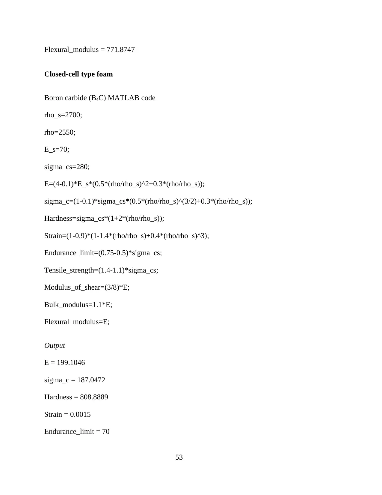
Closed-cell type foam
Boron carbide (B4C) MATLAB code
rho_s=2700;
rho=2550;
E_s=70;
sigma_cs=280;
E=(4-0.1)*E_s*(0.5*(rho/rho_s)^2+0.3*(rho/rho_s));
sigma_c=(1-0.1)*sigma_cs*(0.5*(rho/rho_s)^(3/2)+0.3*(rho/rho_s));
Hardness=sigma_cs*(1+2*(rho/rho_s));
Strain=(1-0.9)*(1-1.4*(rho/rho_s)+0.4*(rho/rho_s)^3);
Endurance_limit=(0.75-0.5)*sigma_cs;
Tensile_strength=(1.4-1.1)*sigma_cs;
Modulus_of_shear=(3/8)*E;
Bulk_modulus=1.1*E;
Flexural_modulus=E;
Output
E = 199.1046
sigma_c = 187.0472
Hardness = 808.8889
Strain = 0.0015
Endurance_limit = 70
53
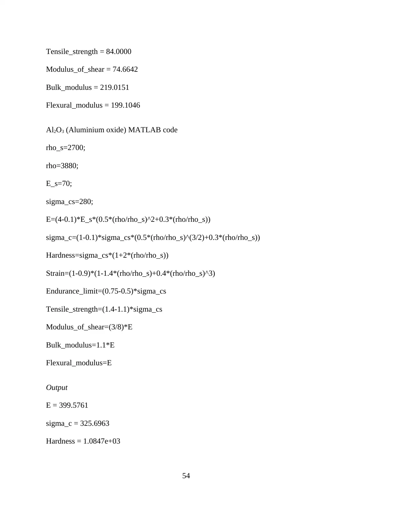
Tensile_strength = 84.0000
Modulus_of_shear = 74.6642
Bulk_modulus = 219.0151
Flexural_modulus = 199.1046
Al2O3 (Aluminium oxide) MATLAB code
rho_s=2700;
rho=3880;
E_s=70;
sigma_cs=280;
E=(4-0.1)*E_s*(0.5*(rho/rho_s)^2+0.3*(rho/rho_s))
sigma_c=(1-0.1)*sigma_cs*(0.5*(rho/rho_s)^(3/2)+0.3*(rho/rho_s))
Hardness=sigma_cs*(1+2*(rho/rho_s))
Strain=(1-0.9)*(1-1.4*(rho/rho_s)+0.4*(rho/rho_s)^3)
Endurance_limit=(0.75-0.5)*sigma_cs
Tensile_strength=(1.4-1.1)*sigma_cs
Modulus_of_shear=(3/8)*E
Bulk_modulus=1.1*E
Flexural_modulus=E
Output
E = 399.5761
sigma_c = 325.6963
Hardness = 1.0847e+03
54
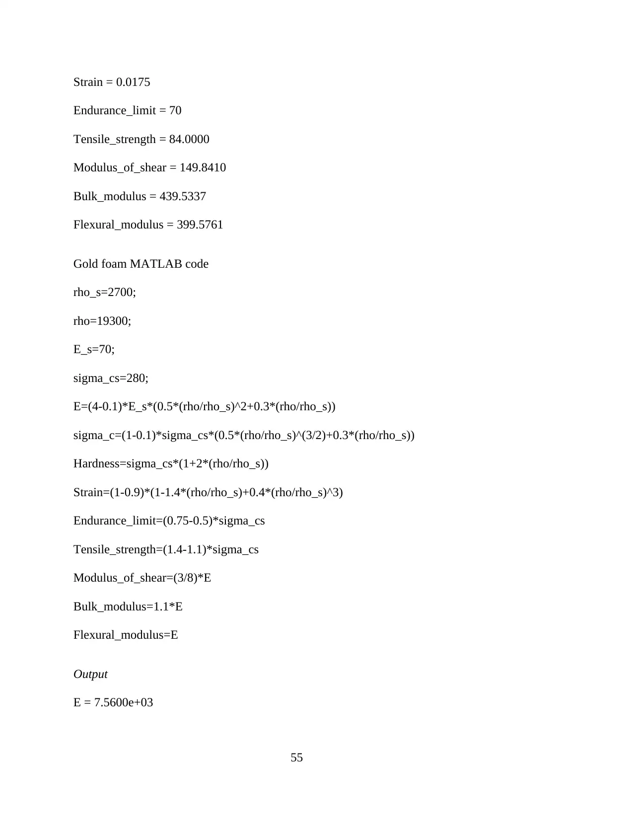
Strain = 0.0175
Endurance_limit = 70
Tensile_strength = 84.0000
Modulus_of_shear = 149.8410
Bulk_modulus = 439.5337
Flexural_modulus = 399.5761
Gold foam MATLAB code
rho_s=2700;
rho=19300;
E_s=70;
sigma_cs=280;
E=(4-0.1)*E_s*(0.5*(rho/rho_s)^2+0.3*(rho/rho_s))
sigma_c=(1-0.1)*sigma_cs*(0.5*(rho/rho_s)^(3/2)+0.3*(rho/rho_s))
Hardness=sigma_cs*(1+2*(rho/rho_s))
Strain=(1-0.9)*(1-1.4*(rho/rho_s)+0.4*(rho/rho_s)^3)
Endurance_limit=(0.75-0.5)*sigma_cs
Tensile_strength=(1.4-1.1)*sigma_cs
Modulus_of_shear=(3/8)*E
Bulk_modulus=1.1*E
Flexural_modulus=E
Output
E = 7.5600e+03
55
Paraphrase This Document
Need a fresh take? Get an instant paraphrase of this document with our AI Paraphraser
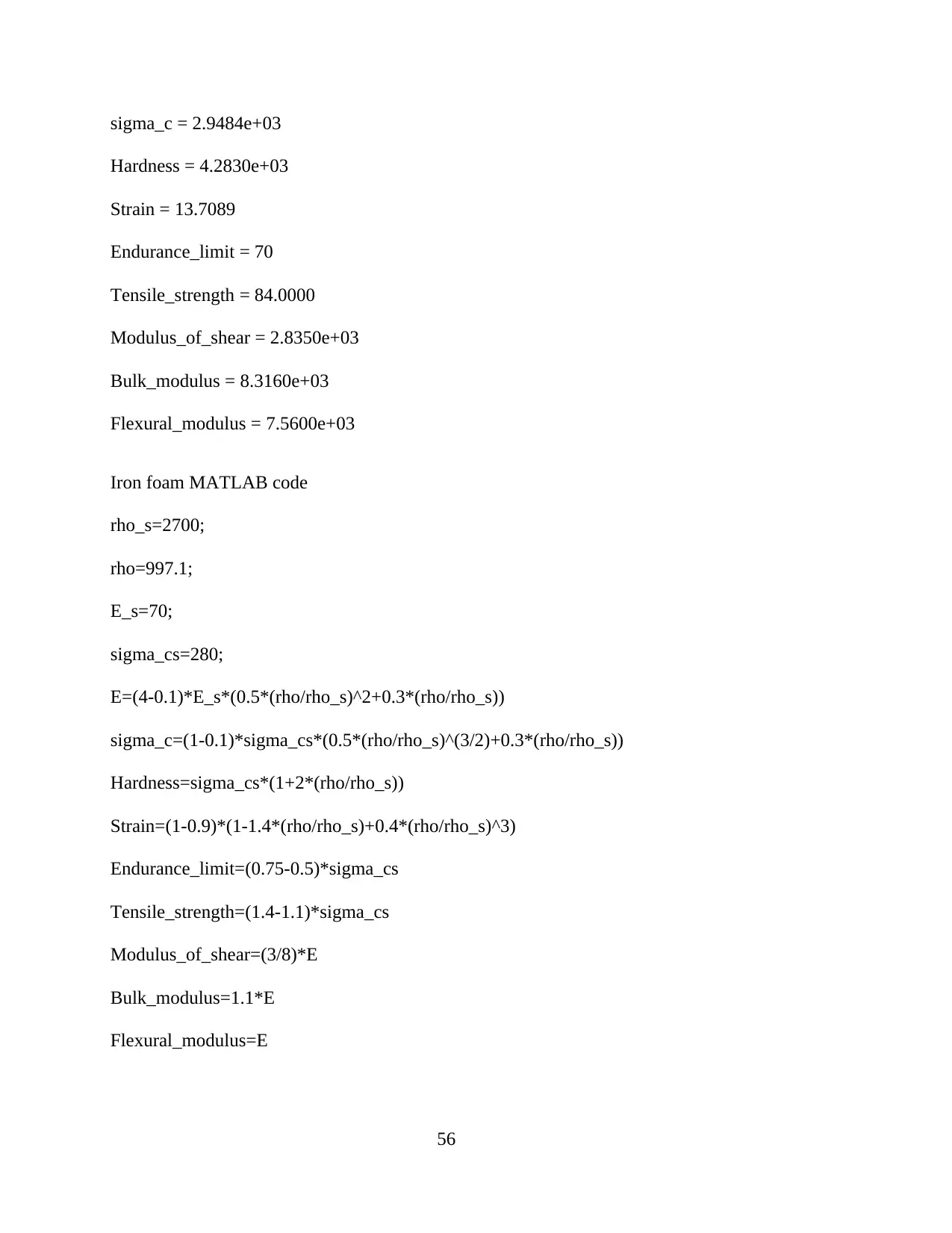
sigma_c = 2.9484e+03
Hardness = 4.2830e+03
Strain = 13.7089
Endurance_limit = 70
Tensile_strength = 84.0000
Modulus_of_shear = 2.8350e+03
Bulk_modulus = 8.3160e+03
Flexural_modulus = 7.5600e+03
Iron foam MATLAB code
rho_s=2700;
rho=997.1;
E_s=70;
sigma_cs=280;
E=(4-0.1)*E_s*(0.5*(rho/rho_s)^2+0.3*(rho/rho_s))
sigma_c=(1-0.1)*sigma_cs*(0.5*(rho/rho_s)^(3/2)+0.3*(rho/rho_s))
Hardness=sigma_cs*(1+2*(rho/rho_s))
Strain=(1-0.9)*(1-1.4*(rho/rho_s)+0.4*(rho/rho_s)^3)
Endurance_limit=(0.75-0.5)*sigma_cs
Tensile_strength=(1.4-1.1)*sigma_cs
Modulus_of_shear=(3/8)*E
Bulk_modulus=1.1*E
Flexural_modulus=E
56
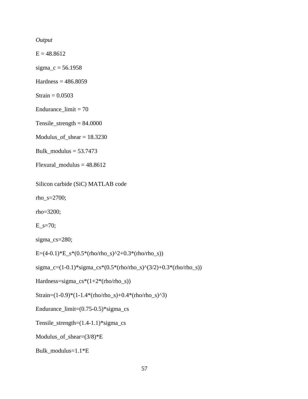
Output
E = 48.8612
sigma_c = 56.1958
Hardness = 486.8059
Strain = 0.0503
Endurance_limit = 70
Tensile_strength = 84.0000
Modulus_of_shear = 18.3230
Bulk_modulus = 53.7473
Flexural_modulus = 48.8612
Silicon carbide (SiC) MATLAB code
rho_s=2700;
rho=3200;
E_s=70;
sigma_cs=280;
E=(4-0.1)*E_s*(0.5*(rho/rho_s)^2+0.3*(rho/rho_s))
sigma_c=(1-0.1)*sigma_cs*(0.5*(rho/rho_s)^(3/2)+0.3*(rho/rho_s))
Hardness=sigma_cs*(1+2*(rho/rho_s))
Strain=(1-0.9)*(1-1.4*(rho/rho_s)+0.4*(rho/rho_s)^3)
Endurance_limit=(0.75-0.5)*sigma_cs
Tensile_strength=(1.4-1.1)*sigma_cs
Modulus_of_shear=(3/8)*E
Bulk_modulus=1.1*E
57
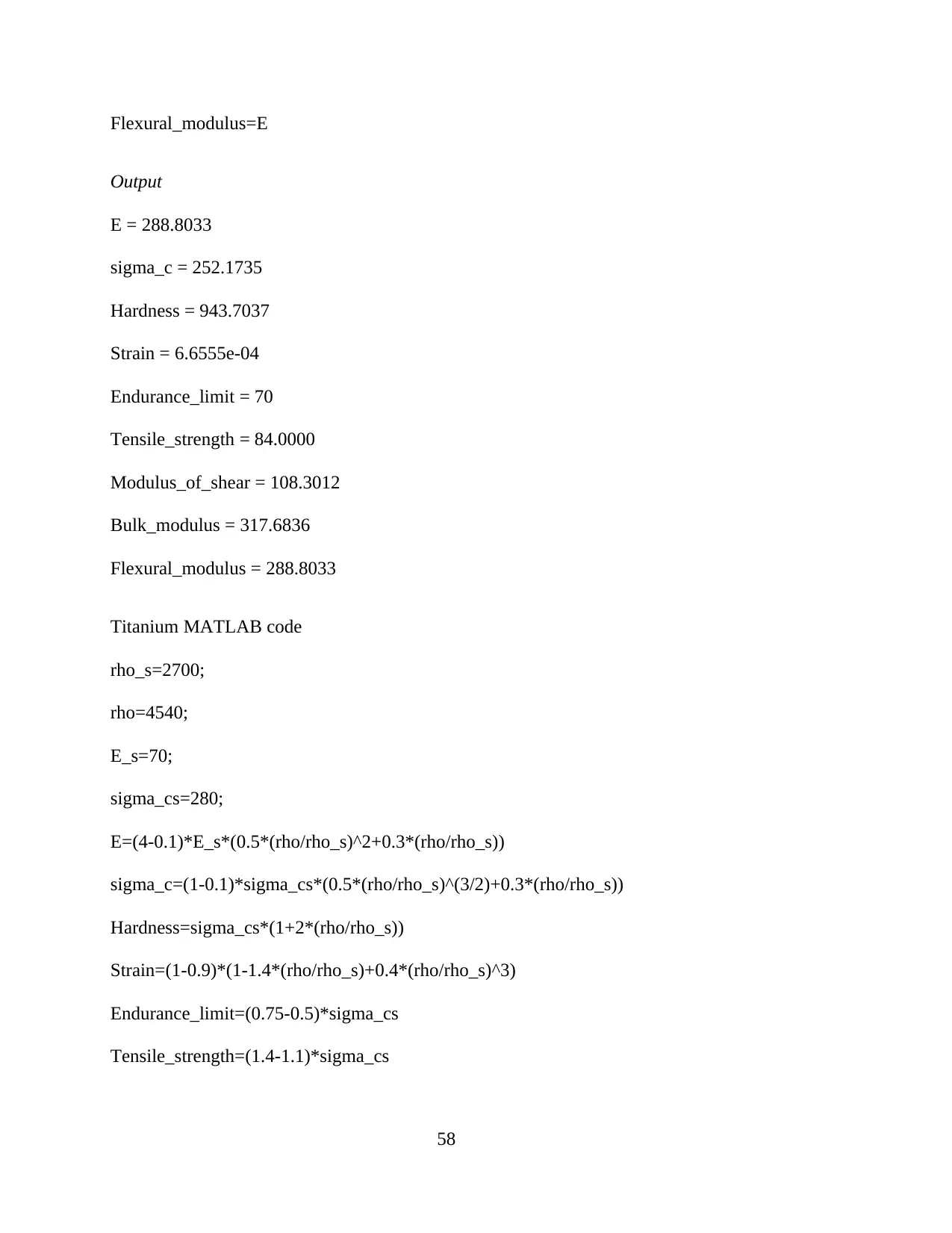
Flexural_modulus=E
Output
E = 288.8033
sigma_c = 252.1735
Hardness = 943.7037
Strain = 6.6555e-04
Endurance_limit = 70
Tensile_strength = 84.0000
Modulus_of_shear = 108.3012
Bulk_modulus = 317.6836
Flexural_modulus = 288.8033
Titanium MATLAB code
rho_s=2700;
rho=4540;
E_s=70;
sigma_cs=280;
E=(4-0.1)*E_s*(0.5*(rho/rho_s)^2+0.3*(rho/rho_s))
sigma_c=(1-0.1)*sigma_cs*(0.5*(rho/rho_s)^(3/2)+0.3*(rho/rho_s))
Hardness=sigma_cs*(1+2*(rho/rho_s))
Strain=(1-0.9)*(1-1.4*(rho/rho_s)+0.4*(rho/rho_s)^3)
Endurance_limit=(0.75-0.5)*sigma_cs
Tensile_strength=(1.4-1.1)*sigma_cs
58
Secure Best Marks with AI Grader
Need help grading? Try our AI Grader for instant feedback on your assignments.
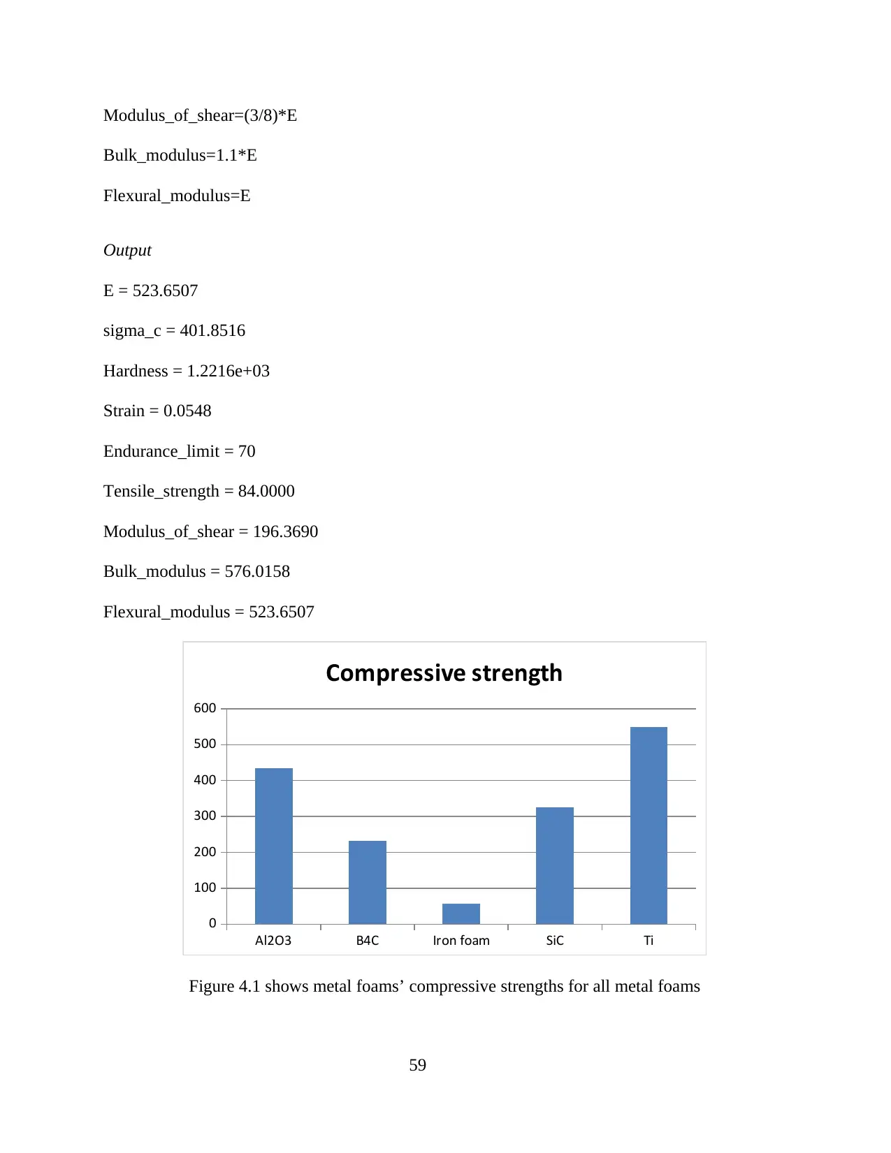
Modulus_of_shear=(3/8)*E
Bulk_modulus=1.1*E
Flexural_modulus=E
Output
E = 523.6507
sigma_c = 401.8516
Hardness = 1.2216e+03
Strain = 0.0548
Endurance_limit = 70
Tensile_strength = 84.0000
Modulus_of_shear = 196.3690
Bulk_modulus = 576.0158
Flexural_modulus = 523.6507
Al2O3 B4C Iron foam SiC Ti
0
100
200
300
400
500
600
Compressive strength
Figure 4.1 shows metal foams’ compressive strengths for all metal foams
59
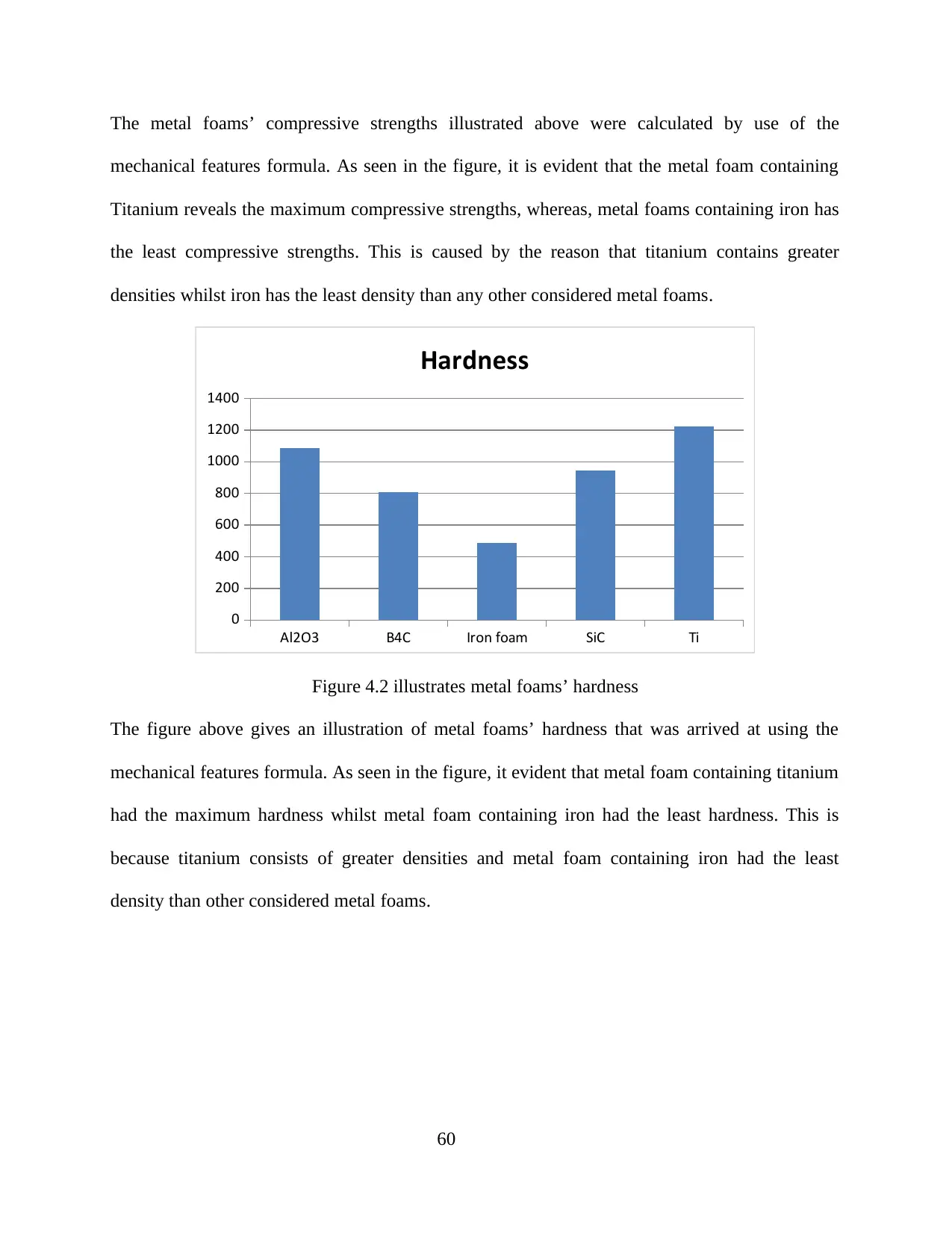
The metal foams’ compressive strengths illustrated above were calculated by use of the
mechanical features formula. As seen in the figure, it is evident that the metal foam containing
Titanium reveals the maximum compressive strengths, whereas, metal foams containing iron has
the least compressive strengths. This is caused by the reason that titanium contains greater
densities whilst iron has the least density than any other considered metal foams.
Al2O3 B4C Iron foam SiC Ti
0
200
400
600
800
1000
1200
1400
Hardness
Figure 4.2 illustrates metal foams’ hardness
The figure above gives an illustration of metal foams’ hardness that was arrived at using the
mechanical features formula. As seen in the figure, it evident that metal foam containing titanium
had the maximum hardness whilst metal foam containing iron had the least hardness. This is
because titanium consists of greater densities and metal foam containing iron had the least
density than other considered metal foams.
60
Al2O3 B4C Iron foam SiC Ti
0
100
200
300
400
500
600
700
800
900
Young's Modulus
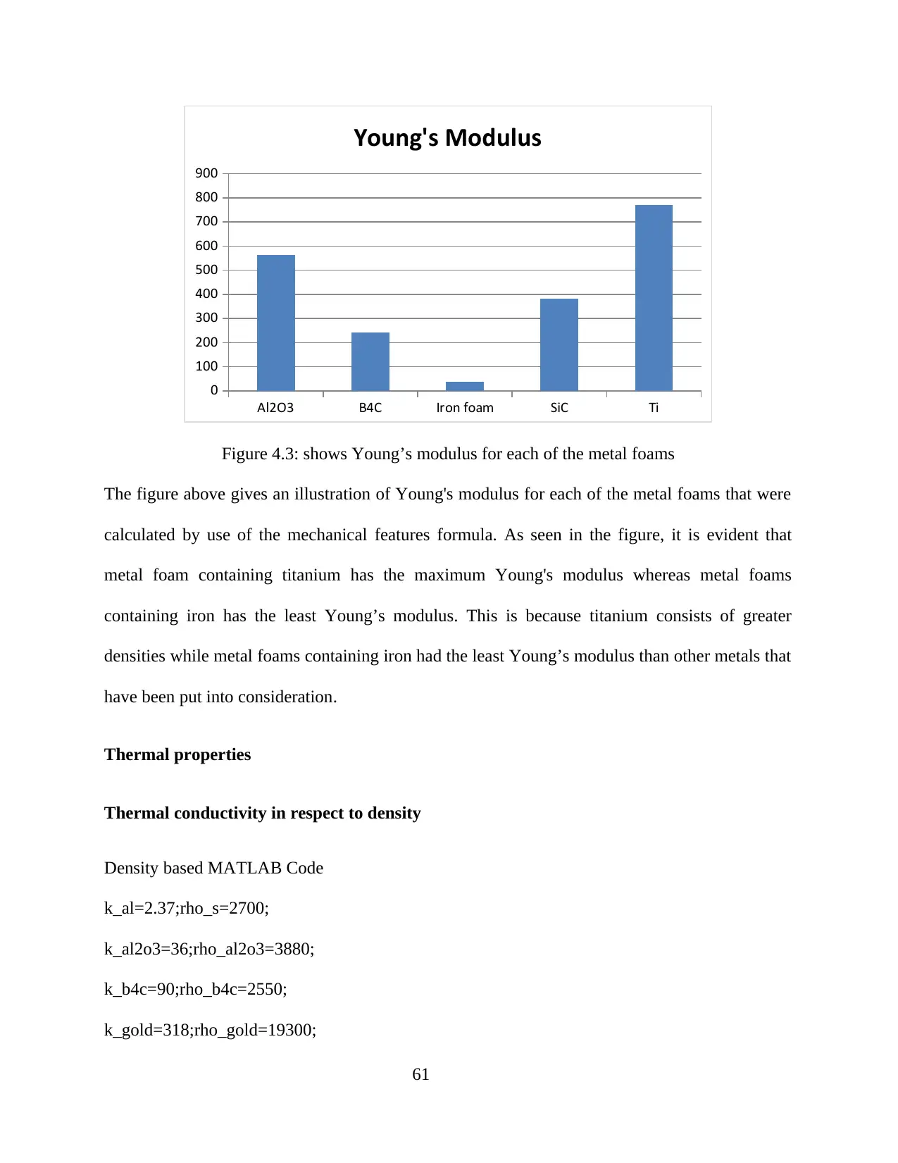
Figure 4.3: shows Young’s modulus for each of the metal foams
The figure above gives an illustration of Young's modulus for each of the metal foams that were
calculated by use of the mechanical features formula. As seen in the figure, it is evident that
metal foam containing titanium has the maximum Young's modulus whereas metal foams
containing iron has the least Young’s modulus. This is because titanium consists of greater
densities while metal foams containing iron had the least Young’s modulus than other metals that
have been put into consideration.
Thermal properties
Thermal conductivity in respect to density
Density based MATLAB Code
k_al=2.37;rho_s=2700;
k_al2o3=36;rho_al2o3=3880;
k_b4c=90;rho_b4c=2550;
k_gold=318;rho_gold=19300;
61
Paraphrase This Document
Need a fresh take? Get an instant paraphrase of this document with our AI Paraphraser
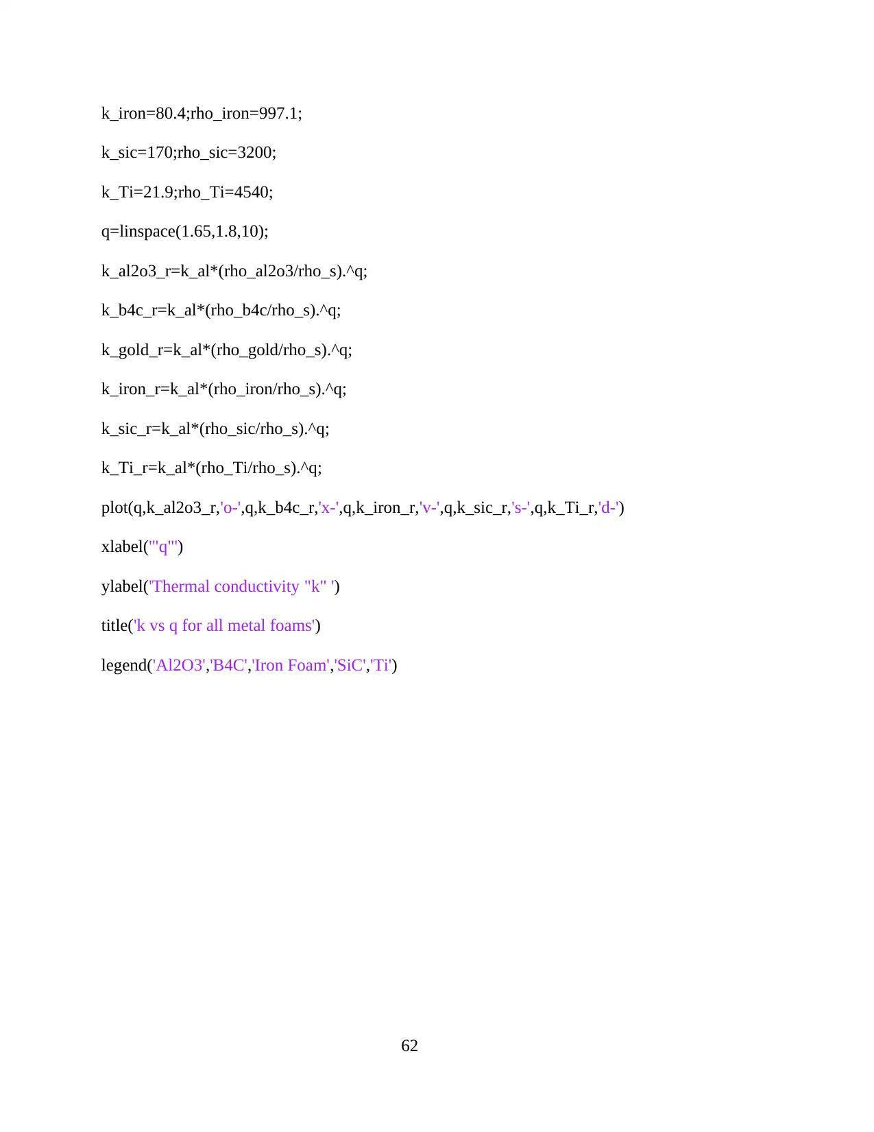
k_iron=80.4;rho_iron=997.1;
k_sic=170;rho_sic=3200;
k_Ti=21.9;rho_Ti=4540;
q=linspace(1.65,1.8,10);
k_al2o3_r=k_al*(rho_al2o3/rho_s).^q;
k_b4c_r=k_al*(rho_b4c/rho_s).^q;
k_gold_r=k_al*(rho_gold/rho_s).^q;
k_iron_r=k_al*(rho_iron/rho_s).^q;
k_sic_r=k_al*(rho_sic/rho_s).^q;
k_Ti_r=k_al*(rho_Ti/rho_s).^q;
plot(q,k_al2o3_r,'o-',q,k_b4c_r,'x-',q,k_iron_r,'v-',q,k_sic_r,'s-',q,k_Ti_r,'d-')
xlabel('"q"')
ylabel('Thermal conductivity "k" ')
title('k vs q for all metal foams')
legend('Al2O3','B4C','Iron Foam','SiC','Ti')
62
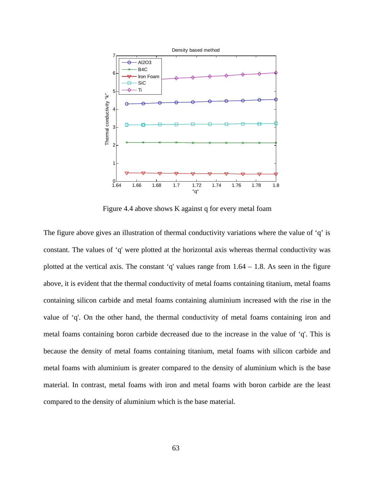
1.64 1.66 1.68 1.7 1.72 1.74 1.76 1.78 1.8
0
1
2
3
4
5
6
7
"q"
Thermal conductivity "k"
Density based method
Al2O3
B4C
Iron Foam
SiC
Ti
Figure 4.4 above shows K against q for every metal foam
The figure above gives an illustration of thermal conductivity variations where the value of ‘q’ is
constant. The values of ‘q' were plotted at the horizontal axis whereas thermal conductivity was
plotted at the vertical axis. The constant ‘q' values range from 1.64 – 1.8. As seen in the figure
above, it is evident that the thermal conductivity of metal foams containing titanium, metal foams
containing silicon carbide and metal foams containing aluminium increased with the rise in the
value of ‘q'. On the other hand, the thermal conductivity of metal foams containing iron and
metal foams containing boron carbide decreased due to the increase in the value of ‘q'. This is
because the density of metal foams containing titanium, metal foams with silicon carbide and
metal foams with aluminium is greater compared to the density of aluminium which is the base
material. In contrast, metal foams with iron and metal foams with boron carbide are the least
compared to the density of aluminium which is the base material.
63

Thermal conductivity in respect to % of reinforcement
Mixture rule MATLAB code
k_al=2.37;rho_s=2700;
k_al2o3=36;rho_al2o3=3880;
k_b4c=90;rho_b4c=2550;
k_gold=318;rho_gold=19300;
k_iron=80.4;rho_iron=997.1;
k_sic=170;rho_sic=3200;
k_Ti=21.9;rho_Ti=4540;
phi=linspace(0,0.05,10);
k_al2o3_mixture=k_al*(1-phi)+k_al2o3*phi;
k_b4c_mixture=k_al*(1-phi)+k_b4c*phi;
k_gold_mixture=k_al*(1-phi)+k_gold*phi;
k_iron_mixture=k_al*(1-phi)+k_iron*phi;
k_sic_mixture=k_al*(1-phi)+k_sic*phi;
k_Ti_mixture=k_al*(1-phi)+k_Ti*phi;
plot(phi,k_al2o3_mixture,'o-',phi,k_b4c_mixture,'x-',phi,k_gold_mixture,'h-',phi,k_iron_mixture,'
v-',phi,k_sic_mixture,'s-',phi,k_Ti_mixture,'d-')
xlabel('"phi"')
ylabel('Thermal conductivity "k" ')
title('k vs phi for all metal foams')
legend('Al2O3','B4C','Gold Foam','Iron Foam','SiC','Ti')
64
Secure Best Marks with AI Grader
Need help grading? Try our AI Grader for instant feedback on your assignments.

0 0.005 0.01 0.015 0.02 0.025 0.03 0.035 0.04 0.045 0.05
2
4
6
8
10
12
14
16
18
20
"phi"
Thermal conductivity "k"
Mixture rule
Al2O3
B4C
Gold Foam
Iron Foam
SiC
Ti
Figure 4.5 above shows K against phi variations for Mixture rule
The figure above gives an illustration of the thermal conductivity variations containing the
percentage of composites reinforcement weight. The values of the percentage composites weight
reinforcement were plotted on the horizontal axis whereas the thermal conductivity was plotted
on the vertical axis. The constant weight percentage of composite reinforcement ranges from 0 –
0.05. As seen in the figure above, it is evident that the considered metal foams' thermal
conductivity increased with the rise in the reinforcement weight percentage of the metal foam
composites into aluminium which is the base metal. It also clear that the metal foams with the
maximum thermal conductivity than the various metal foams have superior thermal conductivity
than the various foams.
Maxwell model MATLAB code
k_al=2.37;rho_s=2700;
k_al2o3=36;rho_al2o3=3880;
65
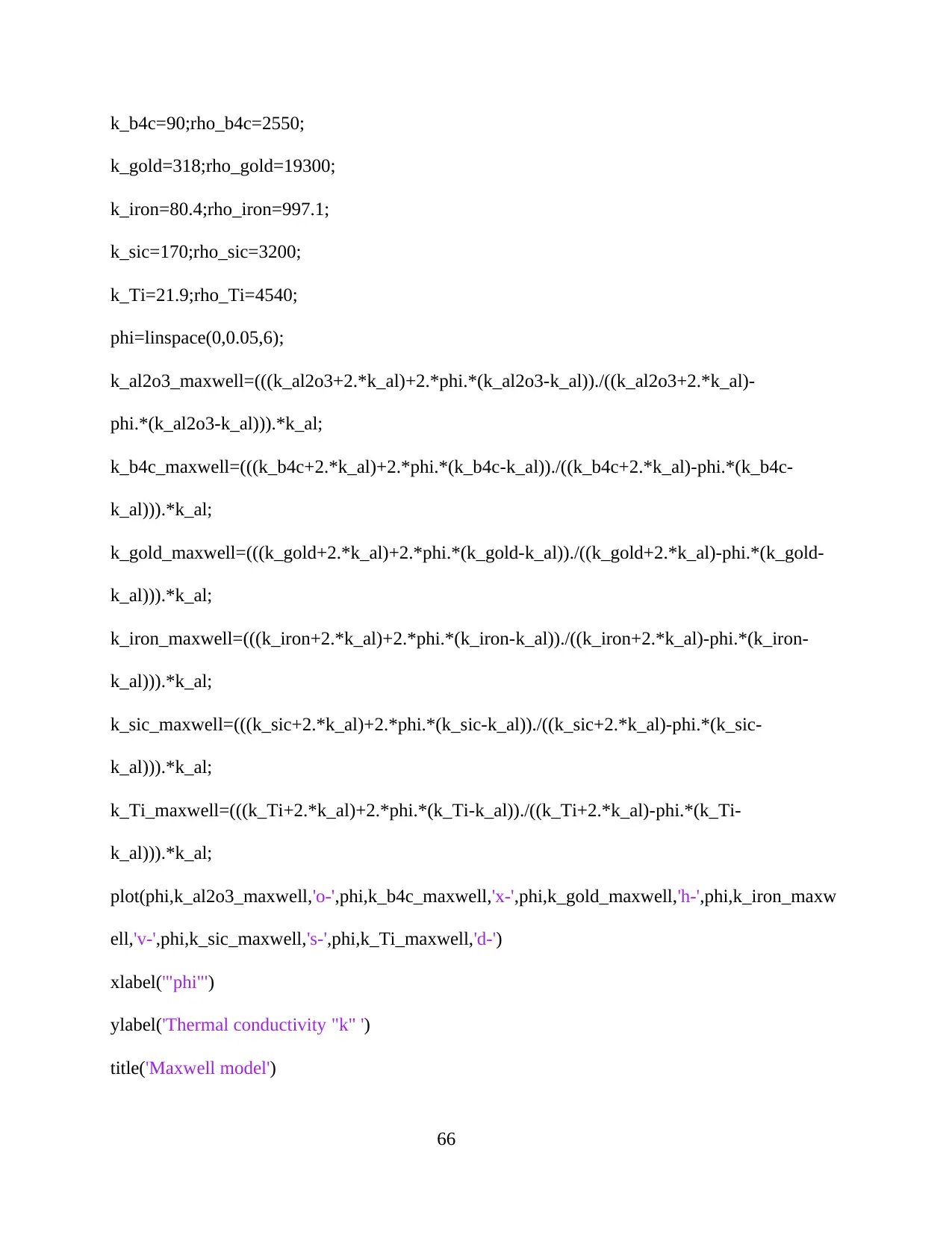
k_b4c=90;rho_b4c=2550;
k_gold=318;rho_gold=19300;
k_iron=80.4;rho_iron=997.1;
k_sic=170;rho_sic=3200;
k_Ti=21.9;rho_Ti=4540;
phi=linspace(0,0.05,6);
k_al2o3_maxwell=(((k_al2o3+2.*k_al)+2.*phi.*(k_al2o3-k_al))./((k_al2o3+2.*k_al)-
phi.*(k_al2o3-k_al))).*k_al;
k_b4c_maxwell=(((k_b4c+2.*k_al)+2.*phi.*(k_b4c-k_al))./((k_b4c+2.*k_al)-phi.*(k_b4c-
k_al))).*k_al;
k_gold_maxwell=(((k_gold+2.*k_al)+2.*phi.*(k_gold-k_al))./((k_gold+2.*k_al)-phi.*(k_gold-
k_al))).*k_al;
k_iron_maxwell=(((k_iron+2.*k_al)+2.*phi.*(k_iron-k_al))./((k_iron+2.*k_al)-phi.*(k_iron-
k_al))).*k_al;
k_sic_maxwell=(((k_sic+2.*k_al)+2.*phi.*(k_sic-k_al))./((k_sic+2.*k_al)-phi.*(k_sic-
k_al))).*k_al;
k_Ti_maxwell=(((k_Ti+2.*k_al)+2.*phi.*(k_Ti-k_al))./((k_Ti+2.*k_al)-phi.*(k_Ti-
k_al))).*k_al;
plot(phi,k_al2o3_maxwell,'o-',phi,k_b4c_maxwell,'x-',phi,k_gold_maxwell,'h-',phi,k_iron_maxw
ell,'v-',phi,k_sic_maxwell,'s-',phi,k_Ti_maxwell,'d-')
xlabel('"phi"')
ylabel('Thermal conductivity "k" ')
title('Maxwell model')
66

legend('Al2O3','B4C','Gold Foam','Iron Foam','SiC','Ti','Location','NorthWest')
0 0.005 0.01 0.015 0.02 0.025 0.03 0.035 0.04 0.045 0.05
2.35
2.4
2.45
2.5
2.55
2.6
2.65
2.7
2.75
"phi"
Thermal conductivity "k"
Maxwell model
Al2O3
B4C
Gold Foam
Iron Foam
SiC
Ti
Figure 4.6 above shows K against phi for the Maxwell model
The figure above outlines the thermal conductivity variations comprising of the percentage
weight of composites reinforcement. Thermal conductivity was plotted on the axis vertically
whereas the percentage weight of composite reinforcement values was plotted on the axis
horizontally. The constant percentage values of reinforced composite weight range from 0 – 0.05.
As demonstrated in the above figure, it is clear that, the considered metal foams’ thermal
conductivity rise due to the increase in the reinforced weight percentage of the metal foam
composites into aluminium which is the base metal. It is also clear that metal foams with superior
thermal conductivities than most of the metal foams indicate greater thermal conductivity
increment.
67
Paraphrase This Document
Need a fresh take? Get an instant paraphrase of this document with our AI Paraphraser
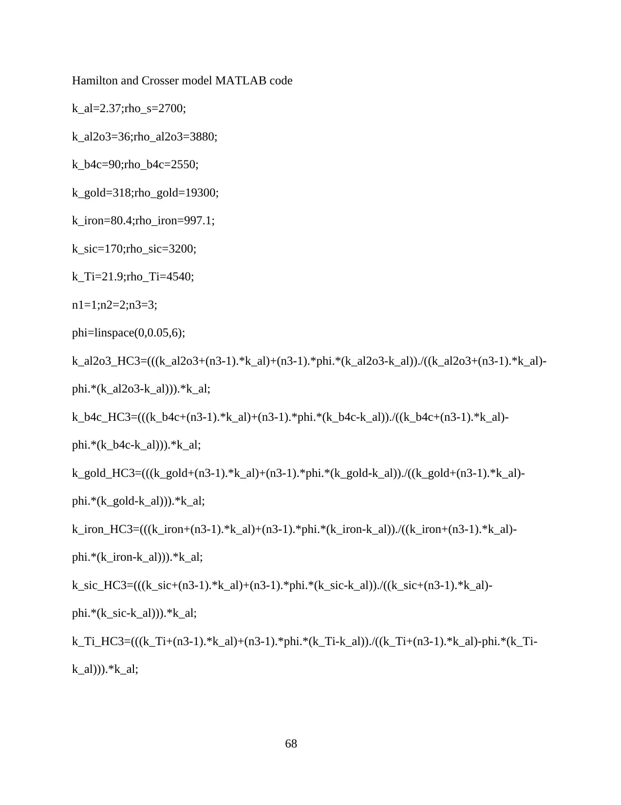
Hamilton and Crosser model MATLAB code
k_al=2.37;rho_s=2700;
k_al2o3=36;rho_al2o3=3880;
k_b4c=90;rho_b4c=2550;
k_gold=318;rho_gold=19300;
k_iron=80.4;rho_iron=997.1;
k_sic=170;rho_sic=3200;
k_Ti=21.9;rho_Ti=4540;
n1=1;n2=2;n3=3;
phi=linspace(0,0.05,6);
k_al2o3_HC3=(((k_al2o3+(n3-1).*k_al)+(n3-1).*phi.*(k_al2o3-k_al))./((k_al2o3+(n3-1).*k_al)-
phi.*(k_al2o3-k_al))).*k_al;
k_b4c_HC3=(((k_b4c+(n3-1).*k_al)+(n3-1).*phi.*(k_b4c-k_al))./((k_b4c+(n3-1).*k_al)-
phi.*(k_b4c-k_al))).*k_al;
k_gold_HC3=(((k_gold+(n3-1).*k_al)+(n3-1).*phi.*(k_gold-k_al))./((k_gold+(n3-1).*k_al)-
phi.*(k_gold-k_al))).*k_al;
k_iron_HC3=(((k_iron+(n3-1).*k_al)+(n3-1).*phi.*(k_iron-k_al))./((k_iron+(n3-1).*k_al)-
phi.*(k_iron-k_al))).*k_al;
k_sic_HC3=(((k_sic+(n3-1).*k_al)+(n3-1).*phi.*(k_sic-k_al))./((k_sic+(n3-1).*k_al)-
phi.*(k_sic-k_al))).*k_al;
k_Ti_HC3=(((k_Ti+(n3-1).*k_al)+(n3-1).*phi.*(k_Ti-k_al))./((k_Ti+(n3-1).*k_al)-phi.*(k_Ti-
k_al))).*k_al;
68
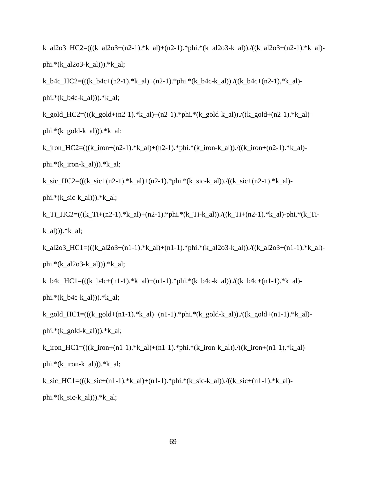
k_al2o3_HC2=(((k_al2o3+(n2-1).*k_al)+(n2-1).*phi.*(k_al2o3-k_al))./((k_al2o3+(n2-1).*k_al)-
phi.*(k_al2o3-k_al))).*k_al;
k_b4c_HC2=(((k_b4c+(n2-1).*k_al)+(n2-1).*phi.*(k_b4c-k_al))./((k_b4c+(n2-1).*k_al)-
phi.*(k_b4c-k_al))).*k_al;
k_gold_HC2=(((k_gold+(n2-1).*k_al)+(n2-1).*phi.*(k_gold-k_al))./((k_gold+(n2-1).*k_al)-
phi.*(k_gold-k_al))).*k_al;
k_iron_HC2=(((k_iron+(n2-1).*k_al)+(n2-1).*phi.*(k_iron-k_al))./((k_iron+(n2-1).*k_al)-
phi.*(k_iron-k_al))).*k_al;
k_sic_HC2=(((k_sic+(n2-1).*k_al)+(n2-1).*phi.*(k_sic-k_al))./((k_sic+(n2-1).*k_al)-
phi.*(k_sic-k_al))).*k_al;
k_Ti_HC2=(((k_Ti+(n2-1).*k_al)+(n2-1).*phi.*(k_Ti-k_al))./((k_Ti+(n2-1).*k_al)-phi.*(k_Ti-
k_al))).*k_al;
k_al2o3_HC1=(((k_al2o3+(n1-1).*k_al)+(n1-1).*phi.*(k_al2o3-k_al))./((k_al2o3+(n1-1).*k_al)-
phi.*(k_al2o3-k_al))).*k_al;
k_b4c_HC1=(((k_b4c+(n1-1).*k_al)+(n1-1).*phi.*(k_b4c-k_al))./((k_b4c+(n1-1).*k_al)-
phi.*(k_b4c-k_al))).*k_al;
k_gold_HC1=(((k_gold+(n1-1).*k_al)+(n1-1).*phi.*(k_gold-k_al))./((k_gold+(n1-1).*k_al)-
phi.*(k_gold-k_al))).*k_al;
k_iron_HC1=(((k_iron+(n1-1).*k_al)+(n1-1).*phi.*(k_iron-k_al))./((k_iron+(n1-1).*k_al)-
phi.*(k_iron-k_al))).*k_al;
k_sic_HC1=(((k_sic+(n1-1).*k_al)+(n1-1).*phi.*(k_sic-k_al))./((k_sic+(n1-1).*k_al)-
phi.*(k_sic-k_al))).*k_al;
69
phi.*(k_al2o3-k_al))).*k_al;
k_b4c_HC2=(((k_b4c+(n2-1).*k_al)+(n2-1).*phi.*(k_b4c-k_al))./((k_b4c+(n2-1).*k_al)-
phi.*(k_b4c-k_al))).*k_al;
k_gold_HC2=(((k_gold+(n2-1).*k_al)+(n2-1).*phi.*(k_gold-k_al))./((k_gold+(n2-1).*k_al)-
phi.*(k_gold-k_al))).*k_al;
k_iron_HC2=(((k_iron+(n2-1).*k_al)+(n2-1).*phi.*(k_iron-k_al))./((k_iron+(n2-1).*k_al)-
phi.*(k_iron-k_al))).*k_al;
k_sic_HC2=(((k_sic+(n2-1).*k_al)+(n2-1).*phi.*(k_sic-k_al))./((k_sic+(n2-1).*k_al)-
phi.*(k_sic-k_al))).*k_al;
k_Ti_HC2=(((k_Ti+(n2-1).*k_al)+(n2-1).*phi.*(k_Ti-k_al))./((k_Ti+(n2-1).*k_al)-phi.*(k_Ti-
k_al))).*k_al;
k_al2o3_HC1=(((k_al2o3+(n1-1).*k_al)+(n1-1).*phi.*(k_al2o3-k_al))./((k_al2o3+(n1-1).*k_al)-
phi.*(k_al2o3-k_al))).*k_al;
k_b4c_HC1=(((k_b4c+(n1-1).*k_al)+(n1-1).*phi.*(k_b4c-k_al))./((k_b4c+(n1-1).*k_al)-
phi.*(k_b4c-k_al))).*k_al;
k_gold_HC1=(((k_gold+(n1-1).*k_al)+(n1-1).*phi.*(k_gold-k_al))./((k_gold+(n1-1).*k_al)-
phi.*(k_gold-k_al))).*k_al;
k_iron_HC1=(((k_iron+(n1-1).*k_al)+(n1-1).*phi.*(k_iron-k_al))./((k_iron+(n1-1).*k_al)-
phi.*(k_iron-k_al))).*k_al;
k_sic_HC1=(((k_sic+(n1-1).*k_al)+(n1-1).*phi.*(k_sic-k_al))./((k_sic+(n1-1).*k_al)-
phi.*(k_sic-k_al))).*k_al;
69
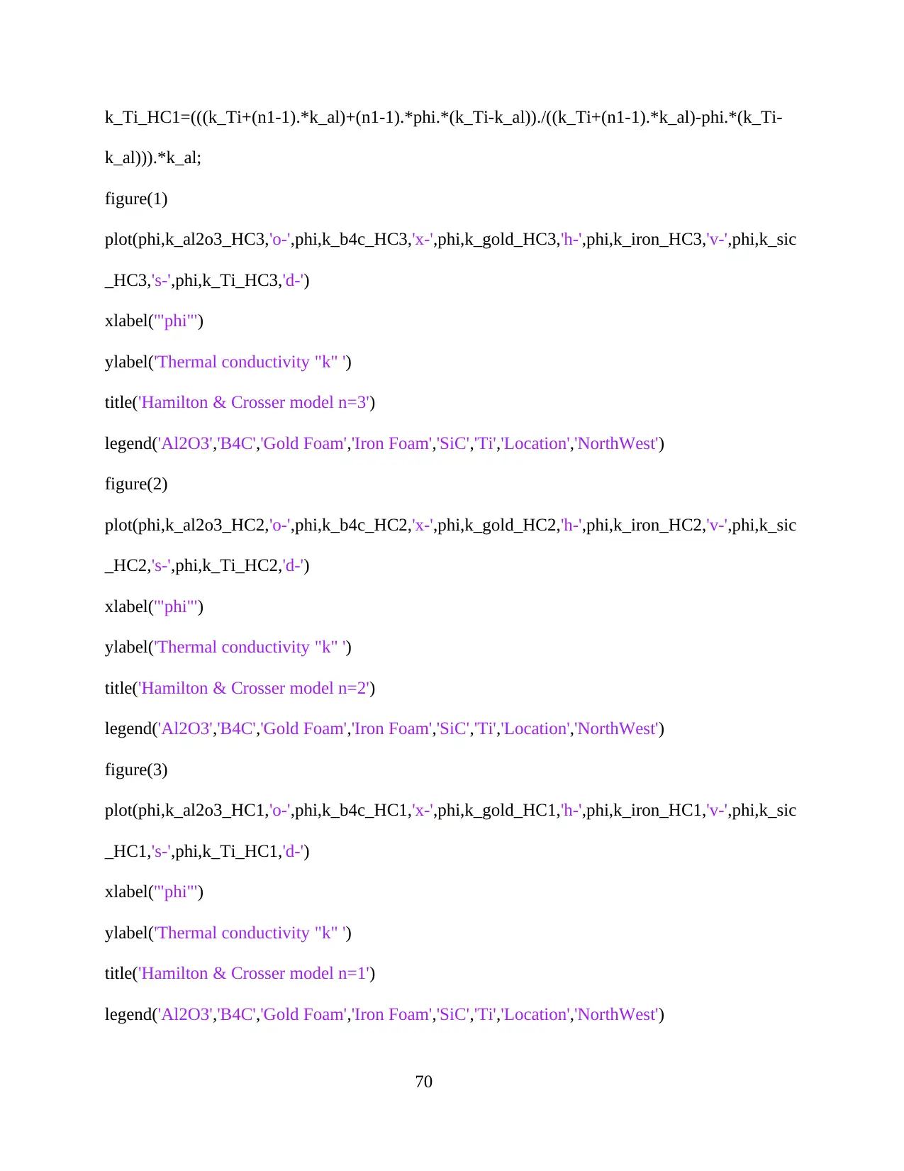
k_Ti_HC1=(((k_Ti+(n1-1).*k_al)+(n1-1).*phi.*(k_Ti-k_al))./((k_Ti+(n1-1).*k_al)-phi.*(k_Ti-
k_al))).*k_al;
figure(1)
plot(phi,k_al2o3_HC3,'o-',phi,k_b4c_HC3,'x-',phi,k_gold_HC3,'h-',phi,k_iron_HC3,'v-',phi,k_sic
_HC3,'s-',phi,k_Ti_HC3,'d-')
xlabel('"phi"')
ylabel('Thermal conductivity "k" ')
title('Hamilton & Crosser model n=3')
legend('Al2O3','B4C','Gold Foam','Iron Foam','SiC','Ti','Location','NorthWest')
figure(2)
plot(phi,k_al2o3_HC2,'o-',phi,k_b4c_HC2,'x-',phi,k_gold_HC2,'h-',phi,k_iron_HC2,'v-',phi,k_sic
_HC2,'s-',phi,k_Ti_HC2,'d-')
xlabel('"phi"')
ylabel('Thermal conductivity "k" ')
title('Hamilton & Crosser model n=2')
legend('Al2O3','B4C','Gold Foam','Iron Foam','SiC','Ti','Location','NorthWest')
figure(3)
plot(phi,k_al2o3_HC1,'o-',phi,k_b4c_HC1,'x-',phi,k_gold_HC1,'h-',phi,k_iron_HC1,'v-',phi,k_sic
_HC1,'s-',phi,k_Ti_HC1,'d-')
xlabel('"phi"')
ylabel('Thermal conductivity "k" ')
title('Hamilton & Crosser model n=1')
legend('Al2O3','B4C','Gold Foam','Iron Foam','SiC','Ti','Location','NorthWest')
70
Secure Best Marks with AI Grader
Need help grading? Try our AI Grader for instant feedback on your assignments.
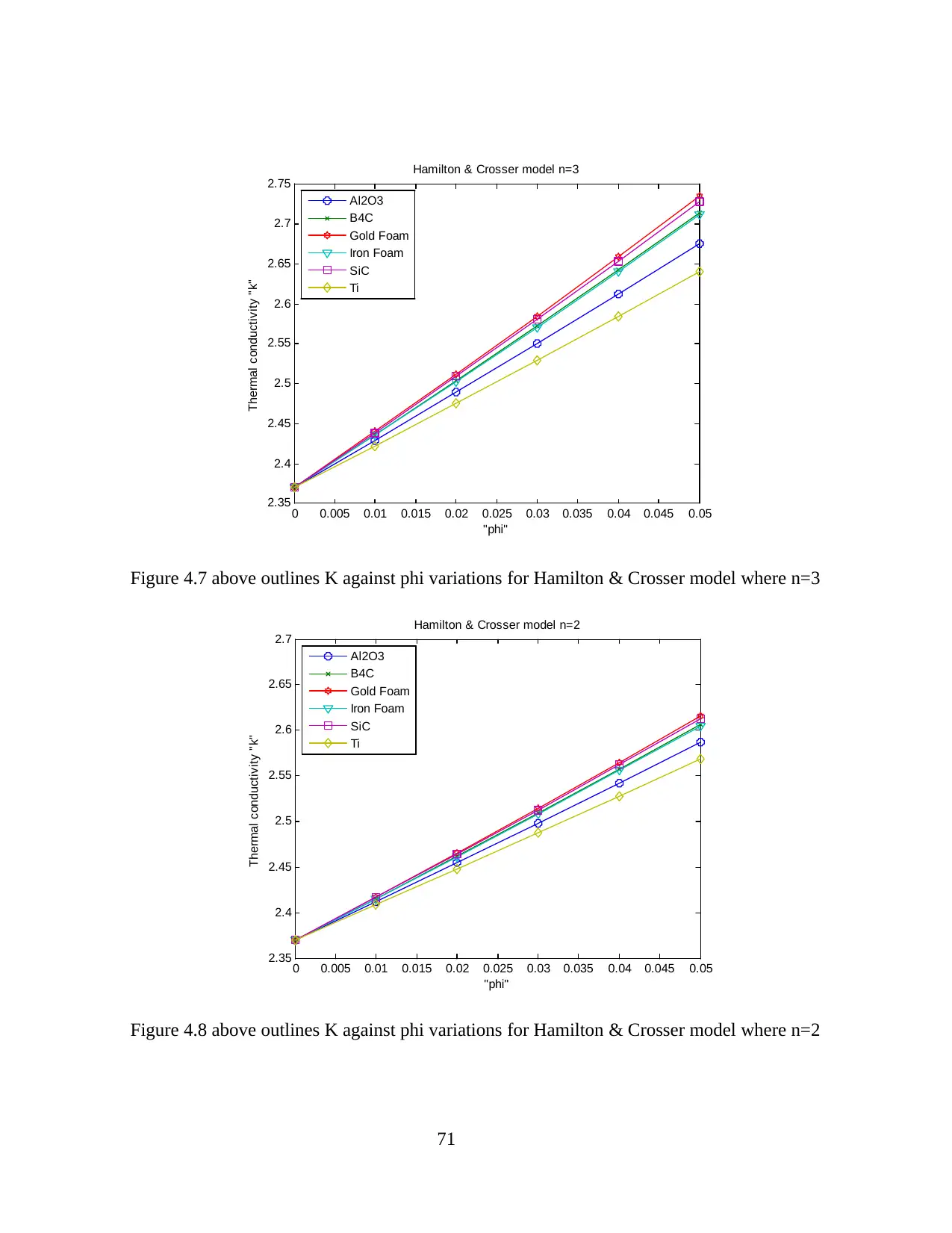
0 0.005 0.01 0.015 0.02 0.025 0.03 0.035 0.04 0.045 0.05
2.35
2.4
2.45
2.5
2.55
2.6
2.65
2.7
2.75
"phi"
Thermal conductivity "k"
Hamilton & Crosser model n=3
Al2O3
B4C
Gold Foam
Iron Foam
SiC
Ti
Figure 4.7 above outlines K against phi variations for Hamilton & Crosser model where n=3
0 0.005 0.01 0.015 0.02 0.025 0.03 0.035 0.04 0.045 0.05
2.35
2.4
2.45
2.5
2.55
2.6
2.65
2.7
"phi"
Thermal conductivity "k"
Hamilton & Crosser model n=2
Al2O3
B4C
Gold Foam
Iron Foam
SiC
Ti
Figure 4.8 above outlines K against phi variations for Hamilton & Crosser model where n=2
71
2.35
2.4
2.45
2.5
2.55
2.6
2.65
2.7
2.75
"phi"
Thermal conductivity "k"
Hamilton & Crosser model n=3
Al2O3
B4C
Gold Foam
Iron Foam
SiC
Ti
Figure 4.7 above outlines K against phi variations for Hamilton & Crosser model where n=3
0 0.005 0.01 0.015 0.02 0.025 0.03 0.035 0.04 0.045 0.05
2.35
2.4
2.45
2.5
2.55
2.6
2.65
2.7
"phi"
Thermal conductivity "k"
Hamilton & Crosser model n=2
Al2O3
B4C
Gold Foam
Iron Foam
SiC
Ti
Figure 4.8 above outlines K against phi variations for Hamilton & Crosser model where n=2
71
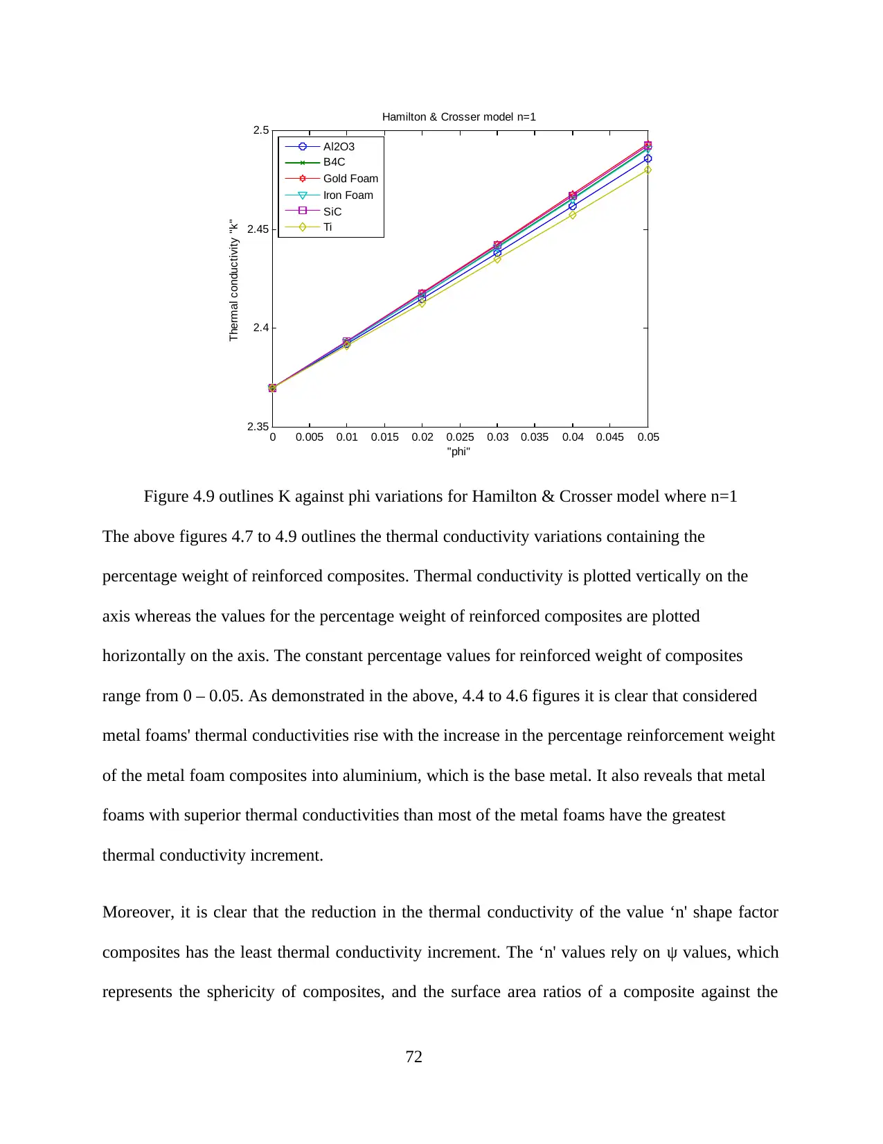
0 0.005 0.01 0.015 0.02 0.025 0.03 0.035 0.04 0.045 0.05
2.35
2.4
2.45
2.5
"phi"
Thermal conductivity "k"
Hamilton & Crosser model n=1
Al2O3
B4C
Gold Foam
Iron Foam
SiC
Ti
Figure 4.9 outlines K against phi variations for Hamilton & Crosser model where n=1
The above figures 4.7 to 4.9 outlines the thermal conductivity variations containing the
percentage weight of reinforced composites. Thermal conductivity is plotted vertically on the
axis whereas the values for the percentage weight of reinforced composites are plotted
horizontally on the axis. The constant percentage values for reinforced weight of composites
range from 0 – 0.05. As demonstrated in the above, 4.4 to 4.6 figures it is clear that considered
metal foams' thermal conductivities rise with the increase in the percentage reinforcement weight
of the metal foam composites into aluminium, which is the base metal. It also reveals that metal
foams with superior thermal conductivities than most of the metal foams have the greatest
thermal conductivity increment.
Moreover, it is clear that the reduction in the thermal conductivity of the value ‘n' shape factor
composites has the least thermal conductivity increment. The ‘n' values rely on ψ values, which
represents the sphericity of composites, and the surface area ratios of a composite against the
72

composite’s volume. This implies that composites with huge surface areas have superior ψ values
which lead to very small ‘n' values for composite shape factors. The resultant ‘n' values that
small will lead to a lower increase in thermal conductivity.
73
which lead to very small ‘n' values for composite shape factors. The resultant ‘n' values that
small will lead to a lower increase in thermal conductivity.
73
Paraphrase This Document
Need a fresh take? Get an instant paraphrase of this document with our AI Paraphraser
CHAPTER VI: CONCLUSION
Various metal foam types have been recently studied with the application of varied mathematical
models. There are a variety of six metal foams put into account including titanium, aluminium
oxide, silicon carbide, gold, boron carbide and iron. Various mathematical model types were put
into consideration in the analyzation of thermal conductivity. These mathematical models
include; models based reinforcing composites and models based on density.
The following are the outcome of the recent research;
Metal foams with titanium revealed superior compressive strengths, Young’s modulus
and hardness.
Thermal conductivity of metal foams with titanium, metal foamed silicon carbide and
metal foamed aluminium rises with the increase in the value of ‘q’.
Metal foams consisting of superior thermal conductivity have the greatest thermal
conductivity increment.
Metal foamed iron have the least compressive strengths, Young’s modulus and hardness.
The metal foams' thermal conductivities rises with the increase in the percentage of the
reinforced weight of the metal foam composites.
Metal foamed iron and Metal foamed boron’s thermal conductivity reduces with the
increment in the value of ‘q’.
74
REFERENCES
Banhart, J. (2007) ‘Metal Foams — from Fundamental Research to Applications’, Universities
Press Limited: Telangana, India, (May), pp. 279–89.
Biener, J. et al. (2009) ‘Surface chemistry in nanoscale materials’, Materials, 2(4), pp. 2404–
2428.
Billiet, M. et al. (2015) ‘Influence of orientation and radiative heat transfer on aluminum foams
in buoyancy-induced convection’, Materials, 8(10), pp. 6792–6805.
Byakova, A. et al. (2014) ‘The role of foaming agent and processing route in mechanical
performance of fabricated aluminum foams’, Advances in Materials Science and
Engineering, 2014, pp. 95–112.
Crupi, V., Epasto, G. and Guglielmino, E. (2011) ‘Impact Response of Aluminum Foam
Sandwiches for Light-Weight Ship Structures’, Metals, 1(1), pp. 98–112.
Depczynski, W. et al. (2016) ‘Modelling and microstructural characterization of sintered metallic
porous materials’, Materials, 9(7), pp. 1–12.
Duarte, I. and Ferreira, J. M. F. (2016) Composite and nanocomposite metal foams, Materials.
Garcia-Avila, M. and Rabiei, A. (2015) ‘Effect of Sphere Properties on Microstructure and
Mechanical Performance of Cast Composite Metal Foams’, Metals, 5(2), pp. 822–835.
Garcia-Moreno, F. et al. (2011) ‘Metal Foaming Investigated by X-ray Radioscopy’, Metals,
2(1), pp. 10–21.
75
Granitzer, P. and Rumpf, K. (2010) ‘Porous silicon-a versatile host material’, Materials, 3(2), pp.
943–998.
Güner, A., Arıkan, M. and Nebioglu, M. (2015) ‘New Approaches to Aluminum Integral Foam
Production with Casting Methods’, Metals, 5(3), pp. 1553–1565.
Hamilton, R. L., and Crosser, O. K., (1962), ‘Thermal Conductivity of Heterogeneous Two-
Component System’, Industrial and Engineering Chemistry Fundamentals, 1(3), pp. 187-
191.
Hangai, Y. et al. (2015) ‘Fabrication of aluminum tubes filled with aluminum alloy foam by
frictionwelding’, Materials, 8(10), pp. 7180–7190.
Jinnapat, A. and Kennedy, A. (2011) ‘The Manufacture and Characterisation of Aluminium
Foams Made by Investment Casting Using Dissolvable Spherical Sodium Chloride Bead
Preforms’, Metals, 1(1), pp. 49–64.
Koizumi, T. et al. (2011) ‘Method of Preventing Shrinkage of Aluminum Foam Using
Carbonates’, Metals, 2(4), pp. 1–9.
Maxwell, J. C., (1873), ‘A Treatise on Electricity and Magnetism, 1st edition’, Volume 1,
Clarendon Press, pp. 360-366
Romero, C. et al. (2010) A new approach to the computer modeling of amorphous nanoporous
structures of semiconducting and metallic materials: A review, Materials.
Strano, M. et al. (2015) ‘Endurance of damping properties of foam-filled tubes’, Materials, 8(7),
pp. 4061–4079.
76
Secure Best Marks with AI Grader
Need help grading? Try our AI Grader for instant feedback on your assignments.
Vesenjak, M. et al. (2012) ‘Behavior of Metallic Foam under Shock Wave Loading’, Metals,
2(4), pp. 258–264.
Veshchunov, M. S. (2009) ‘Modelling of grain growth kinetics in porous ceramic materials under
normal and irradiation conditions’, Materials, 2(3), pp. 1252–1287.
Xia, R. et al. (2015) ‘The role of computer simulation in nanoporous metals-a review’, Materials,
8(8), pp. 5060–5083.
Zhang, R. and Olin, H. (2014) ‘Porous gold films-a short review on recent progress’, Materials,
7(5), pp. 3834–3854.
77
1 out of 77
Related Documents
Your All-in-One AI-Powered Toolkit for Academic Success.
+13062052269
info@desklib.com
Available 24*7 on WhatsApp / Email
![[object Object]](/_next/static/media/star-bottom.7253800d.svg)
Unlock your academic potential
© 2024 | Zucol Services PVT LTD | All rights reserved.
