Metal Removal Technology: Milling Processes and Analysis
VerifiedAdded on 2023/06/04
|39
|11910
|257
Report
AI Summary
This report delves into the realm of metal removal technology, specifically focusing on milling processes. It begins with an introduction to metal removal, highlighting its significance in primary manufacturing and its use in creating precision features. The report explores the motivation behind the research, which aims to review existing literature to understand milling procedures, technologies, and machine center features. A comprehensive literature review is conducted, covering milling processes, milling machines, reducing milling time, advanced milling techniques, types of milling machines, and tooling. The report then outlines the methods of milling used in the research, including work-piece materials, the design of experiments (DOE), and data analysis. The current progress of the project is discussed, along with a project timeline. The report concludes by summarizing the findings and emphasizing the importance of metal removal technology in various manufacturing processes.
Running head: METAL REMOVAL TECHNOLOGY
Metal Removal Technology
Name of the student:
Name of the university:
Author Note
Metal Removal Technology
Name of the student:
Name of the university:
Author Note
Paraphrase This Document
Need a fresh take? Get an instant paraphrase of this document with our AI Paraphraser
1METAL REMOVAL TECHNOLOGY
Executive summary
The process of metal removal is an innovative economic option regarding primary manufacturing.
Despite the costs of tooling and least setup the huge machining times are requires as it is cost
effective for high amounts. Due to high tolerances and outcomes of the surfaces, as offered by
machining it is used to add and refine precision features for present part. In this research different
processes of metal removal through milling are discussed. Apart from this different process of
milling methods are analyzed. These results are done through processes of experimentation with
suitable time schedule that are analyze on the study.
2METAL REMOVAL TECHNOLOGY
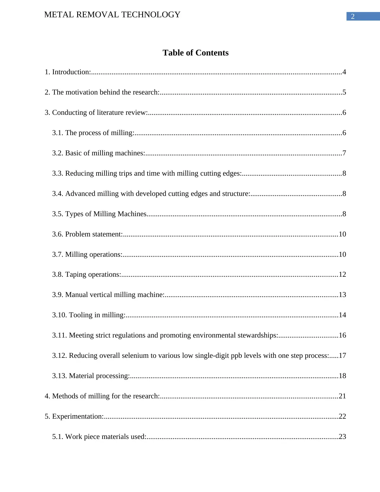
Table of Contents
1. Introduction:......................................................................................................................................4
2. The motivation behind the research:..................................................................................................5
3. Conducting of literature review:........................................................................................................6
3.1. The process of milling:...............................................................................................................6
3.2. Basic of milling machines:.........................................................................................................7
3.3. Reducing milling trips and time with milling cutting edges:.....................................................8
3.4. Advanced milling with developed cutting edges and structure:.................................................8
3.5. Types of Milling Machines.........................................................................................................8
3.6. Problem statement:...................................................................................................................10
3.7. Milling operations:....................................................................................................................10
3.8. Taping operations:....................................................................................................................12
3.9. Manual vertical milling machine:.............................................................................................13
3.10. Tooling in milling:..................................................................................................................14
3.11. Meeting strict regulations and promoting environmental stewardships:................................16
3.12. Reducing overall selenium to various low single-digit ppb levels with one step process:.....17
3.13. Material processing:................................................................................................................18
4. Methods of milling for the research:...............................................................................................21
5. Experimentation:..............................................................................................................................22
5.1. Work piece materials used:.......................................................................................................23
⊘ This is a preview!⊘
Do you want full access?
Subscribe today to unlock all pages.

Trusted by 1+ million students worldwide
3METAL REMOVAL TECHNOLOGY
5.2. Design of experiment (DOE):...................................................................................................24
5.3. Equipment used:.......................................................................................................................24
5.4. Data analysis:............................................................................................................................24
6. The current progresses:....................................................................................................................25
7. Timeline of the current project:.......................................................................................................27
8. Conclusion:......................................................................................................................................29
9. References:......................................................................................................................................31
Paraphrase This Document
Need a fresh take? Get an instant paraphrase of this document with our AI Paraphraser
4METAL REMOVAL TECHNOLOGY
1. Introduction:
The metal removal process or machining is the most financial option as far as primary
manufacturing is concerned. This has been paid for and cutting away and discarding the achievement
of ultimate part. Moreover, despite the tooling costs and least setup, the long machining times has
been needed and thus it is cost prohibitive for huge quantities. Thus metal removal is used for
restricted amount as in fabrication of various prototypes and custom tools. This is for manufacturing
procedures. It is also used commonly as a secondary methods. Here minimal material is eradicated
and overall cycle time is short (Zaretalab et al. 2018). Moreover, because of huge tolerances and
surfaces outcomes, offered by machining, it is utilized for adding and refining various precision
features for current part and smoothing a surface for efficient finish.
Metal removal also involves various procedures, where every elements are removed from the
part or work-piece. Most common metal removal processes are denoted as the traditional machining.
These have been mechanically cutting smaller chips of metals through sharp tools. Besides, non-
traditional machining procedures are used as thermal or chemical means to remove materials. The
traditional processes are placed into three type of categories. This is abrasive machining, multi-point
cutting and single point cutting (Li et al. 2015). Besides, under a given process of various activities
that are done. This has been using particular cutting motions and tools. This machining part has been
needing various operations done with proper planning sequence for developing intended elements.
Milling is the metal removal method through using rotary cutters for removing materials
from work-pieces. This is done through advancing the cutter to work-piece at specific directions.
This is held at a specific angle that is relative to the axis of their tool. In this research various metal
removal processes through milling are demonstrated. Further, various processes of milling methods
5METAL REMOVAL TECHNOLOGY
are analyzed. Further, the results are analyzed and processes of experimentation with proper time
schedule is discussed.
2. The motivation behind the research:
The study aims to review printed materials. This is helpful to gain knowledge and understand
primary milling procedures and theories. Besides, this is useful to become aware of latest
technologies and functions and features of machine centers. This primary vertical know mill
machine is examined, parameters of successful metal removal are recognized. Here applying the
technology to milling is explained. Various machine center functions and features are also
highlighted. Besides different cutting tools, work-changing and work-holding devices are been also
detailed (Khorasani and Yazdi 2017).
At present, various processes are applied where materials are removed with the help of
various processes. This helps in obtaining the final part. The milling machines denotes to the tools
that are designed for solid materials, woods and metals. Very often there milling machines are
automated. These are positioned in different horizontal and vertical orientation for carving out
materials in the basis of pre-existing designs (Wan et al. 2017). Here, the designs are commonly
CAD directed. There are various milling machines that are also CNC operated through
conventionally and manually automated milling devices that are also popular. They are also able to
perform, dynamic movement for work piece and tools. They can also undertake different types of
multi-axis machining. Due to different variation of application, operation and orientation, the milling
machines consists of various functions and numerous principles of operations. As far as tooling is
concerned, the milling machine are outfitted with various heads of tools. This is done to accomplish
various needs of machining. Here, few tools include ball end mills, fluted mills, rounding mills and
cutters. Furthermore, few milling machines have consisted of ends of rotating tools changing the
⊘ This is a preview!⊘
Do you want full access?
Subscribe today to unlock all pages.

Trusted by 1+ million students worldwide
6METAL REMOVAL TECHNOLOGY
dependences in the required activities. Here, the communications with computer programming with
machine are done as there is any change in the tooling.
Various tools used in milling machines are on the basis of intended and material shapes. Due
to the fact that materials such as steel and woods consists of various physical characteristics, the tool
bits are required to be machine those metals properly. As the machine of milling utilizes any tool bits
that are not strong enough for machine steel, the tooling and machines itself also undergoes
damages. This is also strong for soft materials damaging the work-pieces (Stephenson and Agapiou
2016). Here, the primary tooling bit over milling machines are known as cutters. It refers to a shaped
bar consisting saw teeth. This rotates very fast for cutting down and shaping materials. This is
attached to arbors and is known as madel. This includes a shape bar varying in ending, length and
size and used to hold the cutters strongly. A saw ending of millings are oriented, sized and shaped in
various ways. These teeth are located in various orientations in straight up and down manner.
Besides, it is angled in helical orientations and the straight teeth are preferable in operations over
denser materials as the helical teeth creates smooth cuts over soft materials (Sun et al. 2016).
Further, there are various cutters at these categories. This includes t-clot cutters, angle cutters and
dense end cutters. These are subjected to various standard sizes having CAT sizes as the
commonly0utilizwed standardizations categories. As mechanical modelling is a vital feature of this
process of engineering, the review is concentrated of various diffusion, isotherm and kinetic models.
3. Conducting of literature review:
3.1. The process of milling:
It is versatile part of machining processes. This removal of metal is dine through relative
motions of multi-axis, multi-edge cutter, motions of rotating movements of work-pieces. It is a form
of interrupting cutting. Here various repeated cycles of exit and entry motions of those cutting tools
Paraphrase This Document
Need a fresh take? Get an instant paraphrase of this document with our AI Paraphraser
7METAL REMOVAL TECHNOLOGY
has been accomplishing the actual removal of metals with discontinuous generation of chip. Xiao et
al. (2016) mentioned that The milling comprises of variations of machine work-pieces, tooling and
machine types that any other type of machining method. These milling machines coming from
models of tabletops ate the standard vehicle knee mills. They have been operating in similar
principles and parameters of operations. The most vital part of those operating parameters includes
various aspects. The cutting speed is included here which is the speed at which tools has engaged
with the task. Further, it includes feed rates. This includes where the distance tool edge has been
travelling in cuter revolution. Moreover, there is axial depth of cutting. It represents the tools to set
below of machined surfaced. Here, radial depth of cut where the quantity of work surface has been
engaged by that tool. Moreover, the abilities of milling machines are calculated by spindle taper size,
maximum spindle speeds and motor horsepower.
3.2. Basic of milling machines:
The primary milling machine includes vertical spindle, ram-type “knee” mill. However, it is
adapted well for producing milling. This is ideal of making tools and machining prototypes.
Moreover, the knee mills are mainly used for various manual operations. However, Zhou et al.
(2018) argues that these abilities can also expanded. The knee has been travelling vertically, up and
down the columns and supporting table and saddles. Here the saddle has been moving out and in
from column, where table has been moving side by side of that columns. Apart from this, the ram, at
top of that column has been supporting milling head that contains feed controls, speed, tool heads
and motors, spindle and quills. This non-rotating quill has been holding rotating spindles. Here, ram
can be removed from both in and out from that columns and is tilted for drilling and angular milling.
The cutting of tools are secured in collecting and drilling chucks that are held in that spindle. Here,
works are commonly protected to tables through using clamps and bolts through using fixtures and
vises that ate bolted to tables. This work table has containing longitudinal “T” slots for facilitating
8METAL REMOVAL TECHNOLOGY
the attachments of those devices. The abilities of knee mills are expanded through using digital
readout displays and technologies (Wu and Zhang 2014).
3.3. Reducing milling trips and time with milling cutting edges:
The engineers has used pressed sintered carbide of tungsten. These AMT cutters are available
in various metallurgies and shapes. This broad range of cutter has inserted metallurgical and profile
choices. This has been enabling higher flexibilities in designing mills. Here cutting structures
consists of particular properties of performances (Jozić, Bajić and Celent 2015). This is applicable to
base of various applications and tasks. Thus depending on that applications, milling tools have been
including various kinds of AMT cutters for optimizing different aspects of milling operations. These
cutters are designed for taking mills to toughest steels. This includes nickel-content materials and
high-chromes.
3.4. Advanced milling with developed cutting edges and structure:
Then there are cutting structures including cutters that has comprised of developed wear
rates, cutting edges, and impact resistances that has been resulting in shortened milling time. Next,
they are able to withstand abrasive and exotic materials are common to fishing and milling
operations, reducing the time and maximizing performances in broad range of deployments as shown
by Han et al. (2016). This cutters has been sharping profiles with chip-breaking features for
controlling cutting sizes and shapes, enabling efficient cutting removing and management of debris.
3.5. Types of Milling Machines
The machines of milling are differentiated as per orientation to work-pieces and degree of motions.
The first one is knee-type. This a vertical workspace that is been supported by knee. This is an
adjustable vertical casting. This knee supports the saddle and adjusted to allow regarding
customizable workspaces. Then there are plain horizontal and vertical tools. These with standard
⊘ This is a preview!⊘
Do you want full access?
Subscribe today to unlock all pages.

Trusted by 1+ million students worldwide
9METAL REMOVAL TECHNOLOGY
work surfaces are oriented horizontally or vertically. This assembly of tooling is affixed on swivel
and turrets and is positioned parallel to workspaces. This swivel and turret has been allowing the
tools to move freely across work-pieces for enforcing tight kind of tolerances. Then there are
universal horizontal machines of millings as per Canakci and Varol (2015). This differ from plain
horizontal kinds since this is a table swivel housing. This is helpful to move the table in 45 degrees
from the standard horizontal location. This movement of work-piece permits to gain easy angular or
helical operations of milling. Then there are ram type and milling machines. This are also universal
in many cases. It is helpful to allow tooling for positioning them over higher ranges of spaces as the
work pieces. This ram-type machines consist of spindles over movable housings that can move
under any set of horizontal plane. It is a universal ram-type milling machine that involves swivel
housing rising the range of cutting movements. Next, there is swivel cutter head which is a ram-type
milling system. Several cutters with milling machines are able to rotate from a totally vertical to
horizontal position. This workable has been moving and providing the users with liberal degree of
orientation and motion. Various swivel cutters has included hand driven and automatic settings and
rise in options of operations.
According to Al-Sandooq, Yousif and Jensen (2015) the milling is a primary drilling taking
place among various powered processes of metal cutting. It is versatile for basic processes of
machining. However since the milling set up comprises of various degrees of freedom. This milling
is less accurate regarding or turning irrespective of rigid featuring is deployed. There are also manual
machining and is important to fabricate objects that are not symmetric axially. Moreover, there are
broad scopes of various milling machines. This ranges from manual light-duty Bridge-ports. Various
CNC machines regarding milling are consisted of hundreds of feet longs. For example, Cao, Zhou
and Chen (2015) analyzes that organizations such as Sinotech has been offering exceptionally wide
range of secondary procedures applied to metals that are formed in cold or hot processes. Their
Paraphrase This Document
Need a fresh take? Get an instant paraphrase of this document with our AI Paraphraser
10METAL REMOVAL TECHNOLOGY
quality engineers has been finding the availability of processes under metals forming facilities and
quality. As the internal secondary process never meet standards of Sinotech, then the process is done
under Sinotech-audited and qualified facilities of secondary processing. Karagüzel (2015) mentioned
that it has worked, qualified and audited with QS-9000 and various ISO certified secondary
procedures that has been facilitating various nations for many years. It is dedicated to control the
project on-sites and delivering various parts at lower process with same quality, service and terms as
domestic suppliers.
3.6. Problem statement:
As per Maher, Sadeghi and Moheb (2014) the milling is the process to eradicate metals
through feeding tasks against cutters with rotating multipoint. The surface gained by machine tool is
greater in quality and more precise and accurate. Here, the metals ate eradicated through faster rates
as the cutters het various cutting edges and rotating with high speeds. It is also possible to perform
the machine g through mounting more than a single cutter at any instance of time. This table of
machine is moved through accuracy of 0.02 mm. It is also helpful as different cutters and precise
tools are machined. Various special attachments ate mounted on machines for performing operations
done in additional machine tools. However, tyere are various challenges in this section also.
This cost of milling machine has been high.
Since the cost of milling cutters are high, investments to procure the tools are more.
Production cost rises as one carries out operations that are done with specific shape or
drilling machine with milling machines.
11METAL REMOVAL TECHNOLOGY
3.7. Milling operations:
As the process cycle goes on, various operations are done to work-pieces for yielding
intended part shapes. These operations are done with defined kinds of cutters used and oath of
cutters for eradicating metals from work-pieces.
The end-milling indicates making peripheral and slot cuts. This is done through step-over
distances around work pieces for machine specific elements. This includes complicated surface
contour, pockets, slots and profiles according to Machida and Horizoe (2015). Here the depth of the
element is machine in a pass and is reached by machining at least axial depth of cutting and creating
various passes.
Next, there are end milling activities or pocket millings. The first one is chamfer milling.
This makes peripheral cut across edges of work pieces and featuring to develop angles surfaces that
are identified as chamfers. This a typical 45 degree angle and is machines on interior or exterior of
parts and follows curved and straight paths. Next, there is chamfer milling activities. This face mill
machines are flat surfaces of work-pieces for providing smooth finishes. Here the depth of the face is
little and is machines in one pass and is reached through machining smaller axial depth of cutting
and creating numerous passes. Next Luo, et al. (2015) analyzes that there is face milling tasks. Then
there is drilling. This enters the work-pieces in axial manner and cutting hole with diameters that are
same as the tool. This task of drilling is able to create blind holes that extends to some depth within
the work pieces and through holes extending totally through work pieces. Then there is drilling
operations. Here the boring took enter work pieces in axial way and cuts along internal surfaced
forming various features. This is single-point tool of cutting and is set to cut the intended diameter
through using boring heads that are adjustable. This is totally done as drilling the hole for enlarging
diameters and obtaining precise dimensions. Then Lu et al. (2016) discusses that there is the boring
⊘ This is a preview!⊘
Do you want full access?
Subscribe today to unlock all pages.

Trusted by 1+ million students worldwide
1 out of 39
Related Documents
Your All-in-One AI-Powered Toolkit for Academic Success.
+13062052269
info@desklib.com
Available 24*7 on WhatsApp / Email
![[object Object]](/_next/static/media/star-bottom.7253800d.svg)
Unlock your academic potential
Copyright © 2020–2026 A2Z Services. All Rights Reserved. Developed and managed by ZUCOL.


