Design and Simulation of a Hybrid System: PV and Fuel Cell Integration
VerifiedAdded on 2020/05/08
|18
|2508
|255
Project
AI Summary
This project delves into the design, modeling, and simulation of a hybrid energy system that integrates photovoltaic (PV) cells and fuel cells. The system includes a fuel cell, a PV cell, a DC-DC converter, and an inverter, with the fuel cell serving as an alternative power source. The project details the operational principles of each component, including the PV cell's conversion of light to DC electricity, the fuel cell's consumption of hydrogen, and the role of the DC-DC converter and inverter in power management. The simulation is conducted using MATLAB, providing insights into the system's performance under various conditions. The project also explores the application of this hybrid system, particularly in the mobile telecommunication sector, highlighting its potential for providing sustainable energy solutions, especially in remote areas. Furthermore, the project provides detailed calculations and parameter specifications for each component, including PV cell characteristics, fuel cell parameters, and DC-DC converter specifications. The case study of the sustainable energy in the mobile telecommunication sector showcases the practical applications and benefits of hybrid renewable energy systems in reducing reliance on fossil fuels and improving the environmental and socioeconomic standards.
Methodology
Hybrid System with Photovoltaic and fuel cell
Hybrid System with Photovoltaic and fuel cell contains a fuel cell, a
photovoltaic cell, a DC to DC converter and an inverter. The fuel cell is the
other alternative power supply which is used instead of solar radiation.
Power is fed using PV Cell via inverter and DC-DC converter. According to the
power requirement, the hydrogen is consumed by the fuel cell system.
The HES use various RE resources like solar, micro or small hydro, wind,
biomass, with petrol fossil fuel powered or diesel generator for producing
electricity for rural areas which are placed remotely. It is developed on the
base of low cost modelling for the remote rural area. The solar energy is
available on worldwide and free of cost. It can provide DC electricity without
any environmental effects. The photovoltaic fuel cell combine model includes
the path for the valuable energy performance by lowering the fuel cell cost
utilized for this techniques. To simulate the performance of the system, the
matlab simulation software program is used.
1
Paraphrase This Document
Need a fresh take? Get an instant paraphrase of this document with our AI Paraphraser
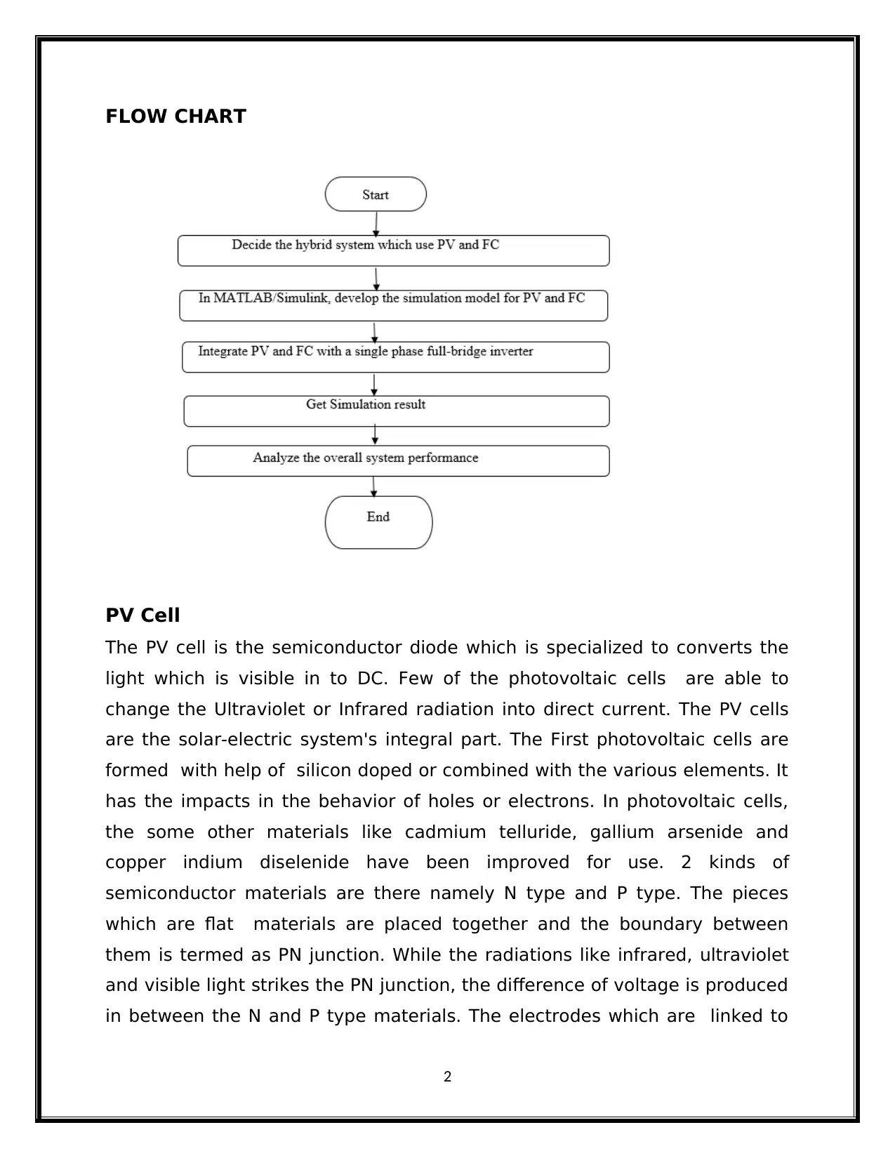
FLOW CHART
PV Cell
The PV cell is the semiconductor diode which is specialized to converts the
light which is visible in to DC. Few of the photovoltaic cells are able to
change the Ultraviolet or Infrared radiation into direct current. The PV cells
are the solar-electric system's integral part. The First photovoltaic cells are
formed with help of silicon doped or combined with the various elements. It
has the impacts in the behavior of holes or electrons. In photovoltaic cells,
the some other materials like cadmium telluride, gallium arsenide and
copper indium diselenide have been improved for use. 2 kinds of
semiconductor materials are there namely N type and P type. The pieces
which are flat materials are placed together and the boundary between
them is termed as PN junction. While the radiations like infrared, ultraviolet
and visible light strikes the PN junction, the difference of voltage is produced
in between the N and P type materials. The electrodes which are linked to
2
the semiconductor layers allows the flow of current. The solar panels, arrays
and models are formed by the large sets of photovoltaic cells. The batteries
and photovoltaic cells usage for a generation of usable electrical energy is
termed as photovoltaic.
The PV array is the basic power conversion unit of the photovoltaic generator
system. PV is composed of modules. The photovoltaic array has a nonlinear
characteristics. It is expensive. It takes more time to obtain the photovoltaic
array operating curves under different operating conditions. Simple and
common solar panel model has been developed. It is integrated to may
engineering software involves Simulink or Matlab.
Calculation for PV cell
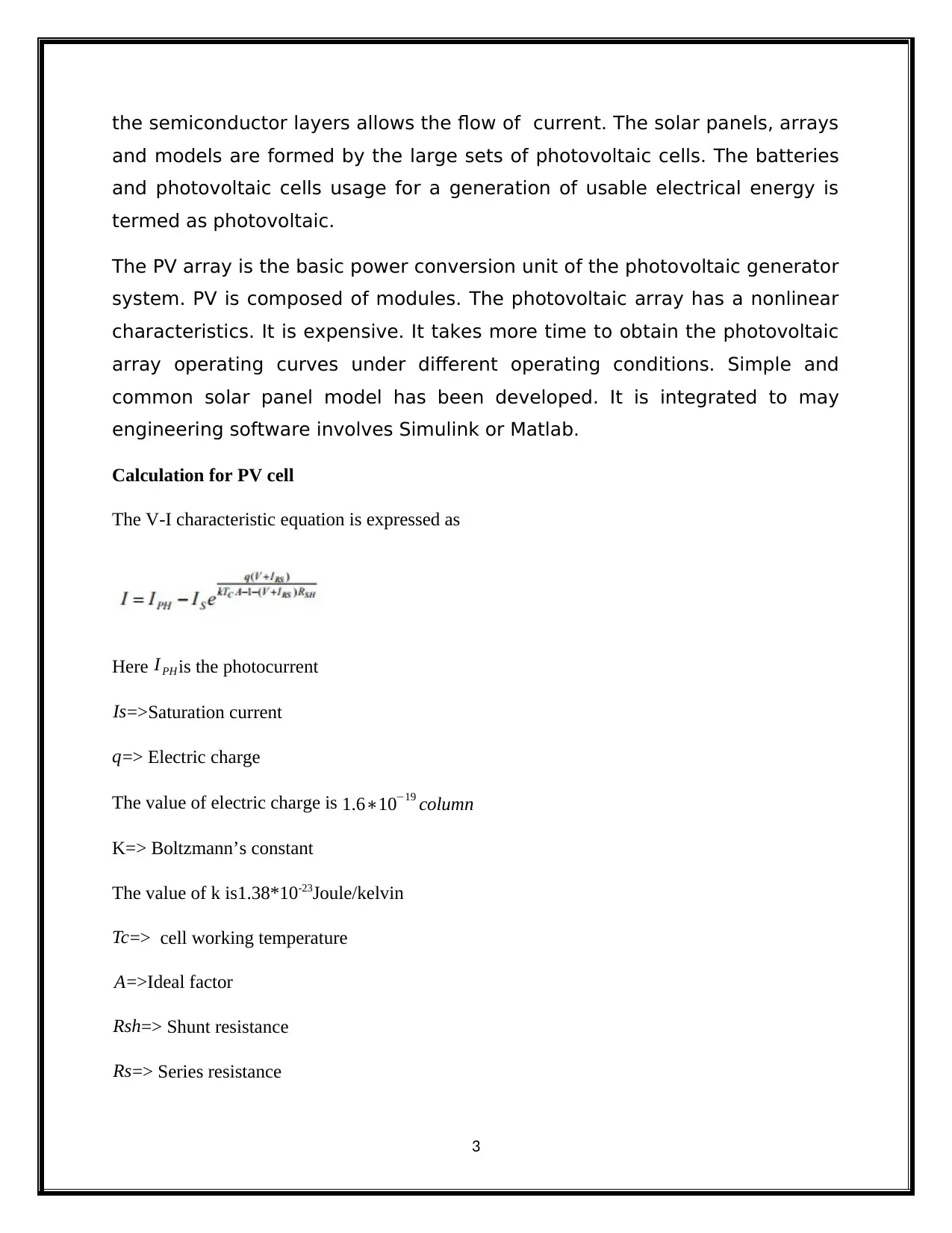
The V-I characteristic equation is expressed as
Here I PH is the photocurrent
Is=>Saturation current
q=> Electric charge
The value of electric charge is 1.6∗10−19 column
K=> Boltzmann’s constant
The value of k is1.38*10-23Joule/kelvin
Tc=> cell working temperature
A=>Ideal factor
Rsh=> Shunt resistance
Rs=> Series resistance
3
⊘ This is a preview!⊘
Do you want full access?
Subscribe today to unlock all pages.

Trusted by 1+ million students worldwide
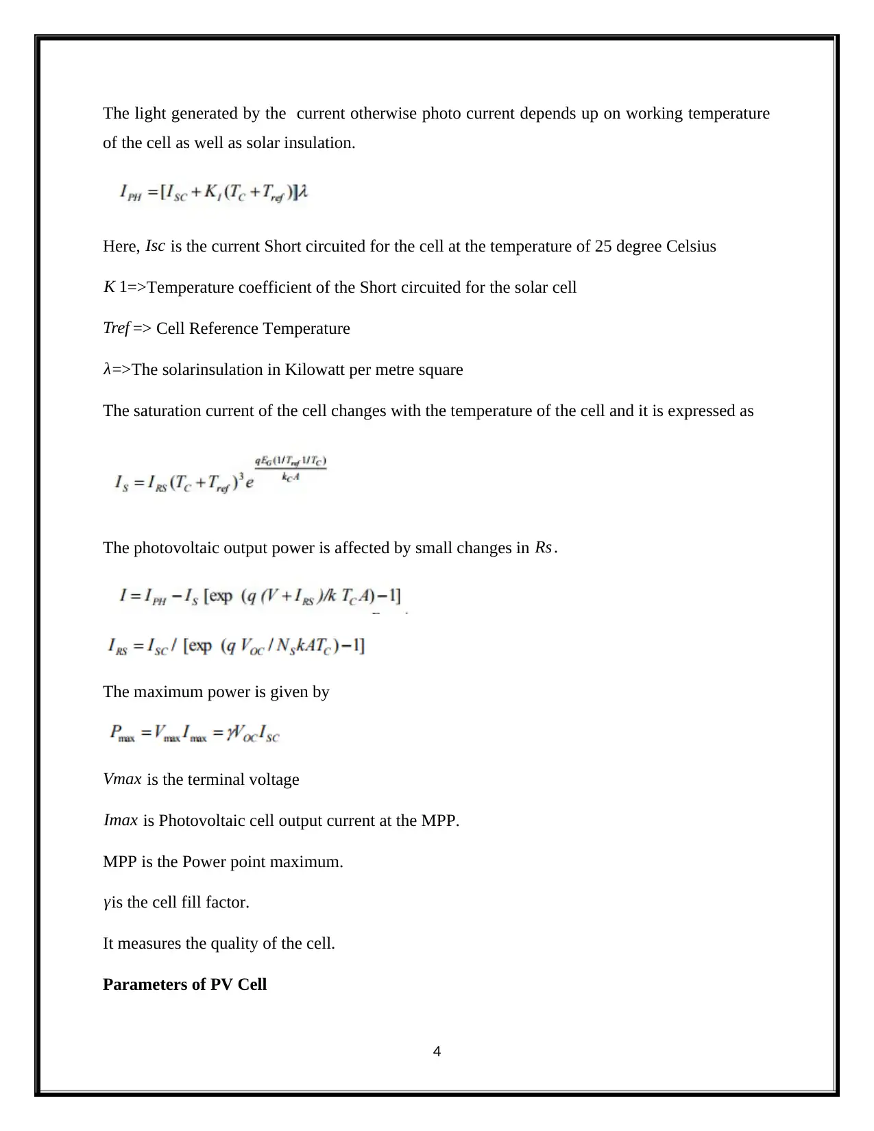
The light generated by the current otherwise photo current depends up on working temperature
of the cell as well as solar insulation.
Here, Isc is the current Short circuited for the cell at the temperature of 25 degree Celsius
K 1=>Temperature coefficient of the Short circuited for the solar cell
Tref => Cell Reference Temperature
λ=>The solarinsulation in Kilowatt per metre square
The saturation current of the cell changes with the temperature of the cell and it is expressed as
The photovoltaic output power is affected by small changes in Rs .
The maximum power is given by
Vmax is the terminal voltage
Imax is Photovoltaic cell output current at the MPP.
MPP is the Power point maximum.
γis the cell fill factor.
It measures the quality of the cell.
Parameters of PV Cell
4
Paraphrase This Document
Need a fresh take? Get an instant paraphrase of this document with our AI Paraphraser
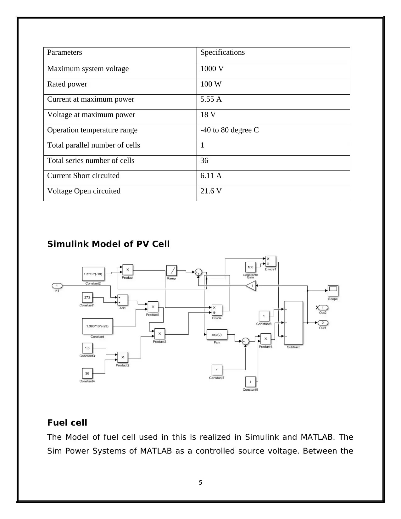
Parameters Specifications
Maximum system voltage 1000 V
Rated power 100 W
Current at maximum power 5.55 A
Voltage at maximum power 18 V
Operation temperature range -40 to 80 degree C
Total parallel number of cells 1
Total series number of cells 36
Current Short circuited 6.11 A
Voltage Open circuited 21.6 V
Simulink Model of PV Cell
Fuel cell
The Model of fuel cell used in this is realized in Simulink and MATLAB. The
Sim Power Systems of MATLAB as a controlled source voltage. Between the
5
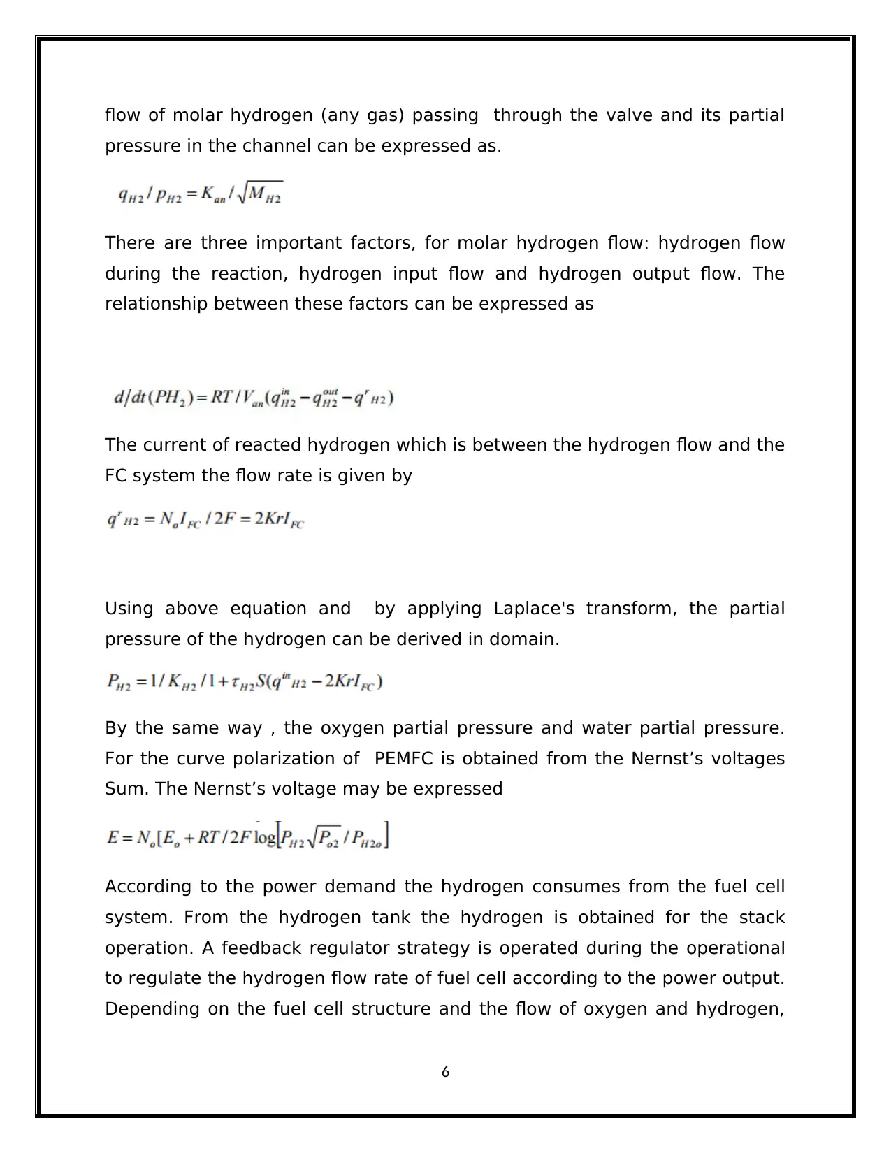
flow of molar hydrogen (any gas) passing through the valve and its partial
pressure in the channel can be expressed as.
There are three important factors, for molar hydrogen flow: hydrogen flow
during the reaction, hydrogen input flow and hydrogen output flow. The
relationship between these factors can be expressed as
The current of reacted hydrogen which is between the hydrogen flow and the
FC system the flow rate is given by
Using above equation and by applying Laplace's transform, the partial
pressure of the hydrogen can be derived in domain.
By the same way , the oxygen partial pressure and water partial pressure.
For the curve polarization of PEMFC is obtained from the Nernst’s voltages
Sum. The Nernst’s voltage may be expressed
According to the power demand the hydrogen consumes from the fuel cell
system. From the hydrogen tank the hydrogen is obtained for the stack
operation. A feedback regulator strategy is operated during the operational
to regulate the hydrogen flow rate of fuel cell according to the power output.
Depending on the fuel cell structure and the flow of oxygen and hydrogen,
6
⊘ This is a preview!⊘
Do you want full access?
Subscribe today to unlock all pages.

Trusted by 1+ million students worldwide
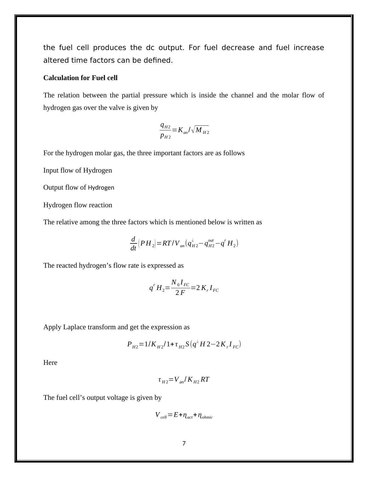
the fuel cell produces the dc output. For fuel decrease and fuel increase
altered time factors can be defined.
Calculation for Fuel cell
The relation between the partial pressure which is inside the channel and the molar flow of
hydrogen gas over the valve is given by
qH 2
pH 2
=Kan / √ M H 2
For the hydrogen molar gas, the three important factors are as follows
Input flow of Hydrogen
Output flow of Hydrogen
Hydrogen flow reaction
The relative among the three factors which is mentioned below is written as
d
dt ( P H 2 ) =RT /V an (qH 2
¿ −qH 2
out −qr H2 )
The reacted hydrogen’s flow rate is expressed as
qr H2= N 0 IFC
2 F =2 Kr I FC
Apply Laplace transform and get the expression as
PH 2 =1/K H 2 /1+ τ H 2 S (q¿ H 2−2 K r I FC)
Here
τ H 2=V an / K H 2 RT
The fuel cell’s output voltage is given by
V cell =E+ɳact + ɳohmic
7
Paraphrase This Document
Need a fresh take? Get an instant paraphrase of this document with our AI Paraphraser
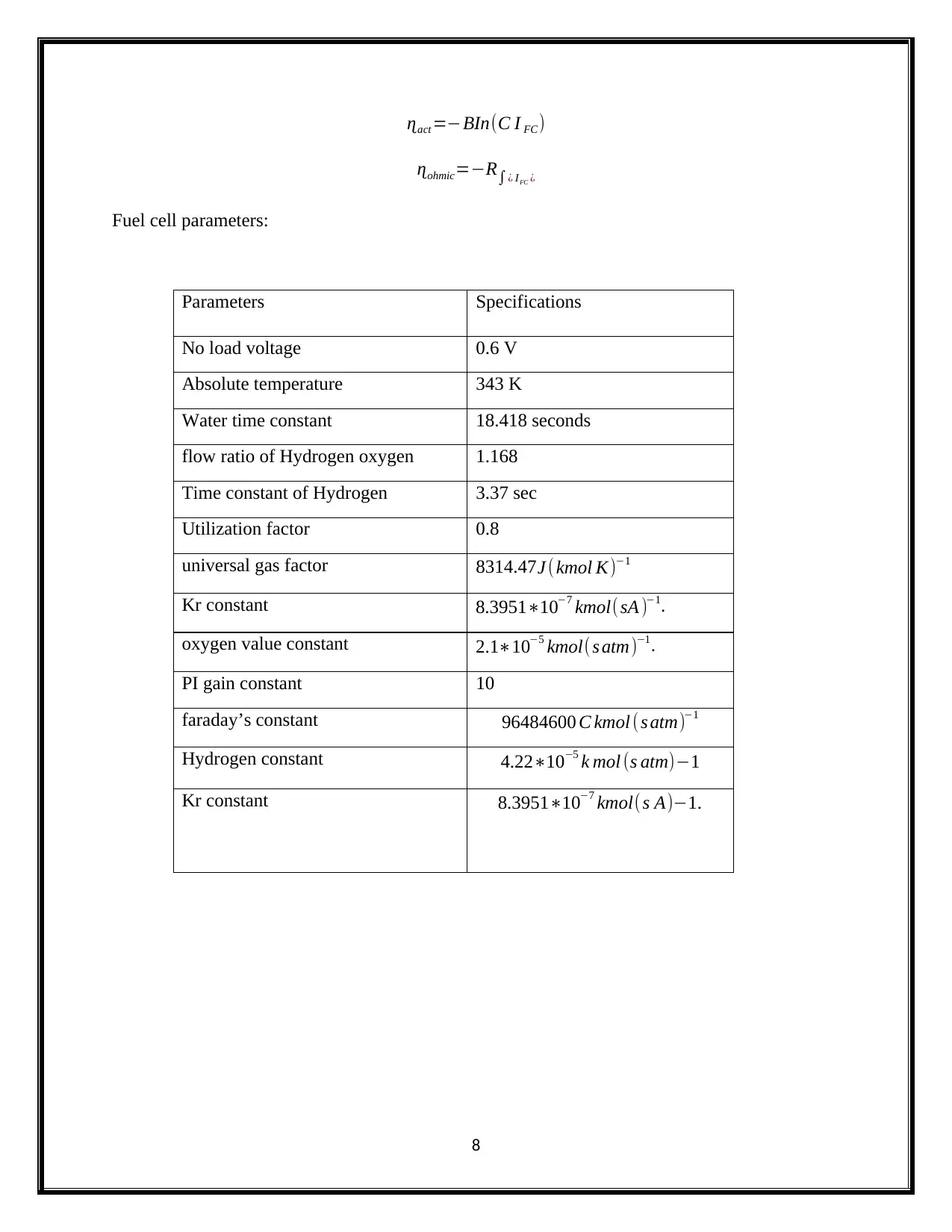
ɳact =−BIn(C I FC)
ɳohmic=−R∫¿ IFC ¿
Fuel cell parameters:
Parameters Specifications
No load voltage 0.6 V
Absolute temperature 343 K
Water time constant 18.418 seconds
flow ratio of Hydrogen oxygen 1.168
Time constant of Hydrogen 3.37 sec
Utilization factor 0.8
universal gas factor 8314.47J ( kmol K)−1
Kr constant 8.3951∗10−7 kmol(sA )−1.
oxygen value constant 2.1∗10−5 kmol(s atm)−1.
PI gain constant 10
faraday’s constant 96484600 C kmol ( s atm)−1
Hydrogen constant 4.22∗10−5 k mol (s atm)−1
Kr constant 8.3951∗10−7 kmol( s A)−1.
8
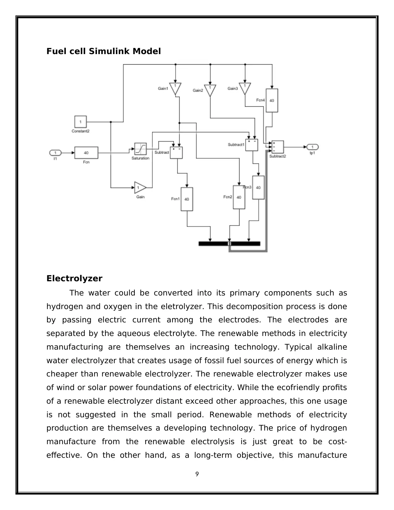
Fuel cell Simulink Model
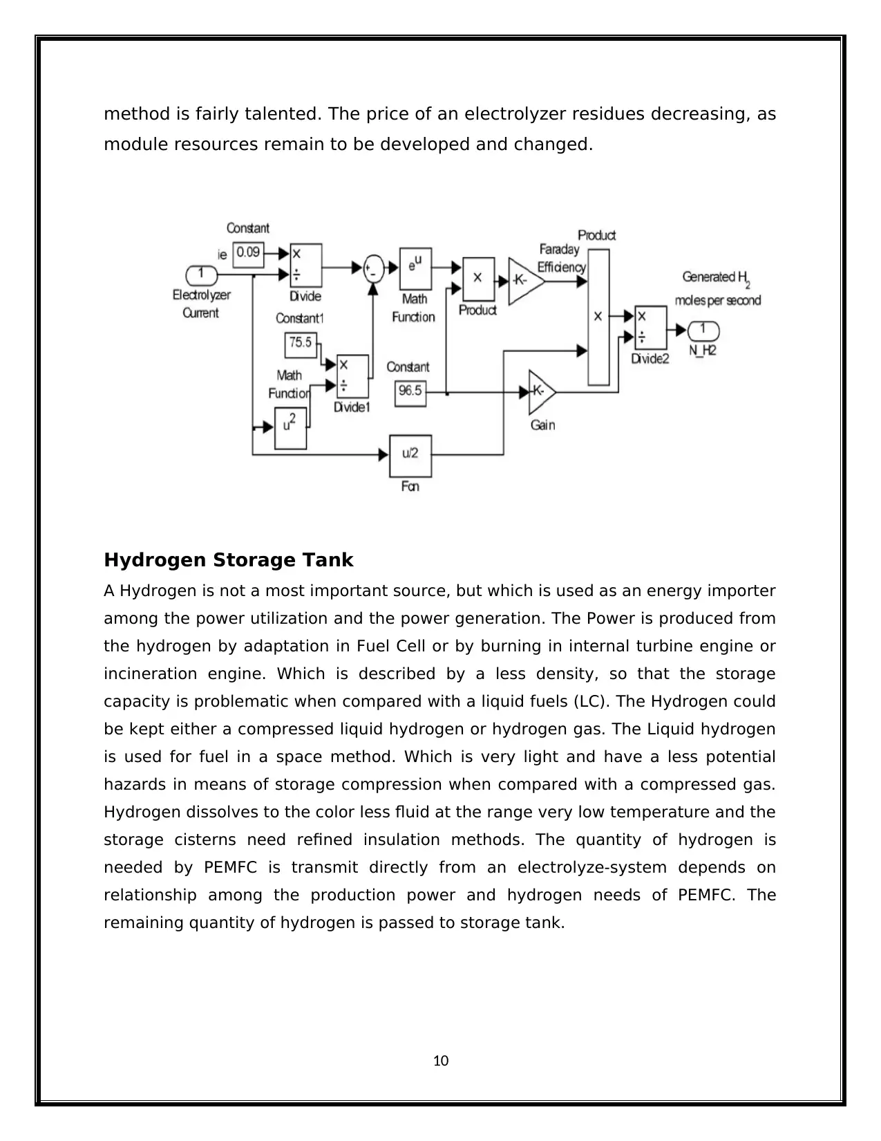
Electrolyzer
The water could be converted into its primary components such as
hydrogen and oxygen in the eletrolyzer. This decomposition process is done
by passing electric current among the electrodes. The electrodes are
separated by the aqueous electrolyte. The renewable methods in electricity
manufacturing are themselves an increasing technology. Typical alkaline
water electrolyzer that creates usage of fossil fuel sources of energy which is
cheaper than renewable electrolyzer. The renewable electrolyzer makes use
of wind or solar power foundations of electricity. While the ecofriendly profits
of a renewable electrolyzer distant exceed other approaches, this one usage
is not suggested in the small period. Renewable methods of electricity
production are themselves a developing technology. The price of hydrogen
manufacture from the renewable electrolysis is just great to be cost-
effective. On the other hand, as a long-term objective, this manufacture
9
⊘ This is a preview!⊘
Do you want full access?
Subscribe today to unlock all pages.

Trusted by 1+ million students worldwide
method is fairly talented. The price of an electrolyzer residues decreasing, as
module resources remain to be developed and changed.
Hydrogen Storage Tank
A Hydrogen is not a most important source, but which is used as an energy importer
among the power utilization and the power generation. The Power is produced from
the hydrogen by adaptation in Fuel Cell or by burning in internal turbine engine or
incineration engine. Which is described by a less density, so that the storage
capacity is problematic when compared with a liquid fuels (LC). The Hydrogen could
be kept either a compressed liquid hydrogen or hydrogen gas. The Liquid hydrogen
is used for fuel in a space method. Which is very light and have a less potential
hazards in means of storage compression when compared with a compressed gas.
Hydrogen dissolves to the color less fluid at the range very low temperature and the
storage cisterns need refined insulation methods. The quantity of hydrogen is
needed by PEMFC is transmit directly from an electrolyze-system depends on
relationship among the production power and hydrogen needs of PEMFC. The
remaining quantity of hydrogen is passed to storage tank.
10
Paraphrase This Document
Need a fresh take? Get an instant paraphrase of this document with our AI Paraphraser
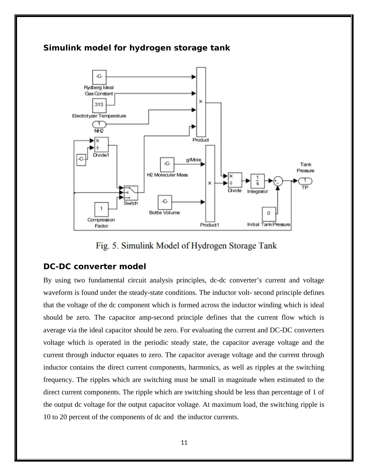
Simulink model for hydrogen storage tank
DC-DC converter model
By using two fundamental circuit analysis principles, dc-dc converter’s current and voltage
waveform is found under the steady-state conditions. The inductor volt- second principle defines
that the voltage of the dc component which is formed across the inductor winding which is ideal
should be zero. The capacitor amp-second principle defines that the current flow which is
average via the ideal capacitor should be zero. For evaluating the current and DC-DC converters
voltage which is operated in the periodic steady state, the capacitor average voltage and the
current through inductor equates to zero. The capacitor average voltage and the current through
inductor contains the direct current components, harmonics, as well as ripples at the switching
frequency. The ripples which are switching must be small in magnitude when estimated to the
direct current components. The ripple which are switching should be less than percentage of 1 of
the output dc voltage for the output capacitor voltage. At maximum load, the switching ripple is
10 to 20 percent of the components of dc and the inductor currents.
11
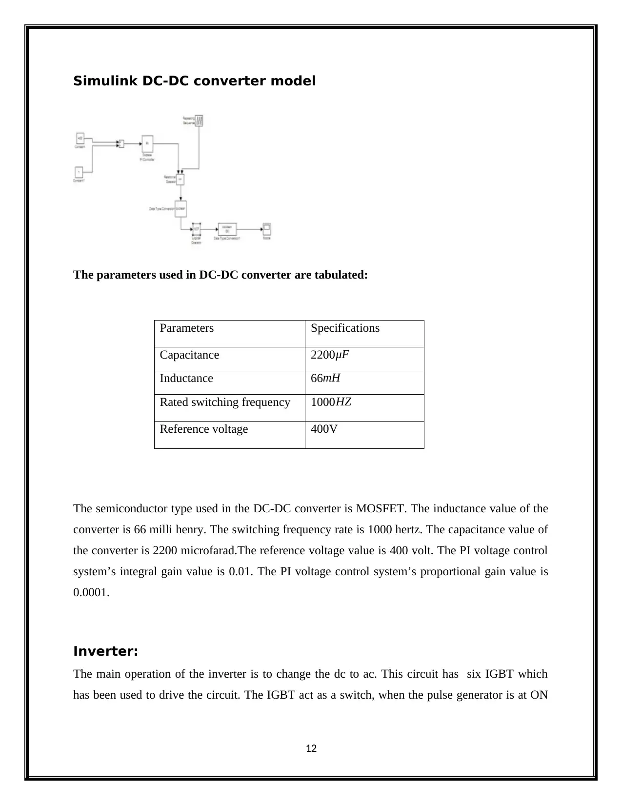
Simulink DC-DC converter model
The parameters used in DC-DC converter are tabulated:
Parameters Specifications
Capacitance 2200 μF
Inductance 66mH
Rated switching frequency 1000 HZ
Reference voltage 400V
The semiconductor type used in the DC-DC converter is MOSFET. The inductance value of the
converter is 66 milli henry. The switching frequency rate is 1000 hertz. The capacitance value of
the converter is 2200 microfarad.The reference voltage value is 400 volt. The PI voltage control
system’s integral gain value is 0.01. The PI voltage control system’s proportional gain value is
0.0001.
Inverter:
The main operation of the inverter is to change the dc to ac. This circuit has six IGBT which
has been used to drive the circuit. The IGBT act as a switch, when the pulse generator is at ON
12
⊘ This is a preview!⊘
Do you want full access?
Subscribe today to unlock all pages.

Trusted by 1+ million students worldwide
1 out of 18
Related Documents
Your All-in-One AI-Powered Toolkit for Academic Success.
+13062052269
info@desklib.com
Available 24*7 on WhatsApp / Email
![[object Object]](/_next/static/media/star-bottom.7253800d.svg)
Unlock your academic potential
Copyright © 2020–2025 A2Z Services. All Rights Reserved. Developed and managed by ZUCOL.


