Ask a question from expert

Ask now

Mobile & Satellite Communication Systems

9 Pages1899 Words192 Views
   

Added on  2020-04-01

Mobile & Satellite Communication Systems

   Added on 2020-04-01

BookmarkShareRelated Documents
QPSK Signal ModulationMELBOURNE INSTITUTE OF TECHNOLOGYSCHOOL OF INFORMATION TECHNOLOGY & ENGINEERINGUNIT CODE: BE302UNIT TITLE: Mobile & Satellite Communication SystemsASSIGNMENT 2QPSK SIGNAL MODULATIONINTRODUCTION
Mobile & Satellite Communication Systems_1
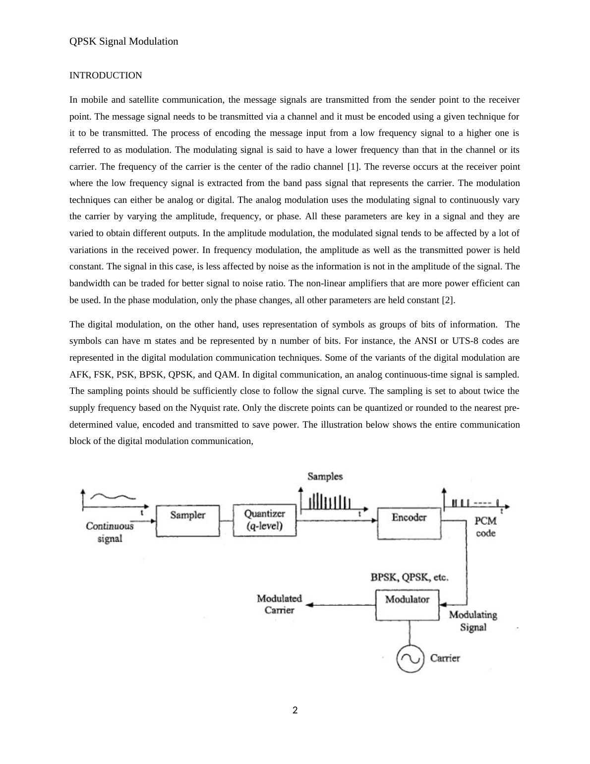
QPSK Signal ModulationIn mobile and satellite communication, the message signals are transmitted from the sender point to the receiver point.The message signal needs to be transmitted via a channel and it must be encoded using a given technique for it to betransmitted. The process of encoding the message input from a low frequency signal to a higher one is referred to asmodulation. The modulating signal is said to have a lower frequency than that in the channel or its carrier. Thefrequency of the carrier is the center of the radio channel[ CITATION Rap02 \l 1033 ]. The reverse occurs at thereceiver point where the low frequency signal is extracted from the band pass signal that represents the carrier. Themodulation techniques can either be analog or digital. The analog modulation uses the modulating signal tocontinuously vary the carrier by varying the amplitude, frequency, or phase. All these parameters are key in a signal andthey are varied to obtain different outputs. In the amplitude modulation, the modulated signal tends to be affected by alot of variations in the received power. In frequency modulation, the amplitude as well as the transmitted power is heldconstant. The signal in this case, is less affected by noise as the information is not in the amplitude of the signal. Thebandwidth can be traded for better signal to noise ratio. The non-linear amplifiers that are more power efficient can beused. In the phase modulation, only the phase changes, all other parameters are held constant[ CITATION Cha00 \l1033 ]. The digital modulation, on the other hand, uses representation of symbols as groups of bits of information. Thesymbols can have m states and be represented by n number of bits. For instance, the ANSI or UTS-8 codes arerepresented in the digital modulation communication techniques. Some of the variants of the digital modulation areAFK, FSK, PSK, BPSK, QPSK, and QAM. In digital communication, an analog continuous-time signal is sampled. Thesampling points should be sufficiently close to follow the signal curve. The sampling is set to about twice the supplyfrequency based on the Nyquist rate. Only the discrete points can be quantized or rounded to the nearest pre-determinedvalue, encoded and transmitted to save power. The illustration below shows the entire communication block of thedigital modulation communication,The symbol rate is defined in bauds per second. Other features are estimated in the digital modulation. The bit error rateis the noise in the channel that can result in errors in received signal. The bit error rate is a likelihood of a bit received
Mobile & Satellite Communication Systems_2
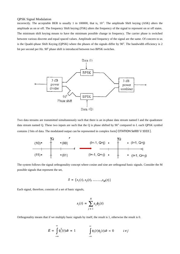
QPSK Signal Modulationincorrectly. The acceptable BER is usually 1 in 100000, that is, 10-5. The amplitude Shift keying (ASK) alters theamplitude as on or off. The frequency Shift keying (FSK) alters the frequency of the signal to represent on or off states.The minimum shift keying means to have the minimum possible change in frequency. The carrier phase is switchedbetween various discrete and equal spaced values. Amplitude and frequency of the signal are the same. Of concern to usis the Quadri-phase Shift Keying (QPSK) where the phases of the signals differ by 900. The bandwidth efficiency is 2bit per second per Hz. 900 phase shift is introduced between two BPSK switches. Two data streams are transmitted simultaneously such that there is an in-phase data stream named I and the quadraturedata stream named Q. These two inputs are such that the Q is phase shifted by 900 compared to I. each QPSK symbolcontains 2 bits of data. The modulated output can be represented in complex form[ CITATION Sel00 \l 1033 ]. The system follows the signal orthogonality concept where cosine and sine are orthogonal basic signals. Consider the Mpossible signals that represent the set,Each signal, therefore, consists of a set of basic signals,Orthogonality means that if we multiply basic signals by itself, the result is 1, otherwise the result is 0.
Mobile & Satellite Communication Systems_3

End of preview

Want to access all the pages? Upload your documents or become a member.

Related Documents
Comparison of Different Modulation Techniques and Error Detection Process
|17
|2315
|81

Wireless Networks and Communications: Encoding, Error Control, Multiplexing, WiFi
|12
|1563
|215

MATLAB Assignment: Communications IV
|18
|2723
|292

Assignment on Multiplexing, Error and Flow Control, and Network Design
|11
|1888
|405

Wireless Networks and Communication Name of Student Institution Affiliation Question 1: Converting Binary Data into Analog Waveforms
|28
|1093
|200

Assignment on Two level Amplitude Shift Keying
|9
|933
|32