SEM712 CAE: Finite Element Analysis of Wired Automotive Frame
VerifiedAdded on 2023/06/14
|13
|1811
|345
Report
AI Summary
This report details a finite element analysis (FEA) conducted using Abaqus to determine the structural response of a wired automotive frame. The primary focus is on modal analysis, which identifies the vibration characteristics, including natural frequencies and mode shapes, of the wire. The study involves simulating the wire's behavior under both unloaded and loaded conditions, with varying concentrated masses attached. The report includes a description of the geometry, material properties of steel, and the FE model used in Abaqus. The results show the impact of increasing concentrated mass on the vibration frequency and the displacement of the structure under a known load. The analysis aims to provide insights into avoiding resonant vibrations and understanding the wire's dynamic behavior. Desklib offers similar solved assignments and resources for students.
Keywords: Modal Frequency, Abaqus, Vibrations
STRUCTURAL RESPONSE OF WIRED AUTOMOTIVE FRAME
Student Name (Student Number)
Email:email address should be a hyperlink
ABSTRACT
For any structure subjected to fluctuating loads, it is essential to correctly determine its eigenvalues and
mode shapes. If the frequency of exciting force resonates with any one of the natural frequency of the structure
(or component) depicts unnatural response to the external loading and sometimes even lead to catastrophic
failure. To determine the eigenvalues we are using Abaqus which is a commercial Finite Element analysis
software. Modal analysis is a technique to determine the vibration characteristic of the structure and it is also the
most fundamental of all the dynamic analyses type. We have considered the material steel for the component. In
this paper, we have attempted to study the basic mode shapes and its effective impact on the structure in loaded
and unloaded conditions.
Table of Contents
ABSTRACT..............................................................................................................................................1
1. Introduction to Modal Analysis...........................................................................................................2
1. What is Modal Analysis?............................................................................................................................2
2. Theory and Terminology............................................................................................................................2
3. Eigen frequencies and Mode Shapes...........................................................................................................2
2. Abaqus Simulation..............................................................................................................................3
2.1 Objective.................................................................................................................................................3
2.2 Geometry................................................................................................................................................3
2.3 Material and Section Properties...............................................................................................................4
2.4 FE Model................................................................................................................................................4
2.5 Vibration Frequency of the First Mode of Just Wire................................................................................5
2.6 Vibration Frequency of the First Mode of Wire with concentrated mass.......................................................6
2.6 Displacement of the structure when loaded at the opposite end with a known load................................9
Conclusion...............................................................................................................................................10
Appendix I: Task Summary.....................................................................................................................11
References...............................................................................................................................................11
1 | P a g e
Paraphrase This Document
Need a fresh take? Get an instant paraphrase of this document with our AI Paraphraser
1. Introduction to Modal Analysis
2. Abaqus Simulation
2.1 Objective
This is report is documented for Task 3 in “Project 1 Structural responses of an arbitrary wire” in
SEM712: CAE and Finite Element Analysis subject. Please see Appendix for the details.
2.2 Geometry
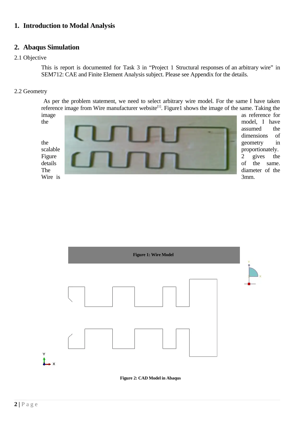
As per the problem statement, we need to select arbitrary wire model. For the same I have taken
reference image from Wire manufacturer website[1]. Figure1 shows the image of the same. Taking the
image as reference for
the model, I have
assumed the
dimensions of
the geometry in
scalable proportionately.
Figure 2 gives the
details of the same.
The diameter of the
Wire is 3mm.
2 | P a g e
Figure 1: Wire Model
Figure 2: CAD Model in Abaqus
2.3 Material and Section Properties
Standard Steel Properties are applied to the wire. The mechanical properties are defined in
consistent unit system as below:
Mass Density Young’s Modulus Poisson’s Ratio
7.85E-009 21000 0.3
The Wire Section Properties are defined as below:
Section Type Material Profile Type Profile radius
Beam Steel Circular r = 1.5 mm
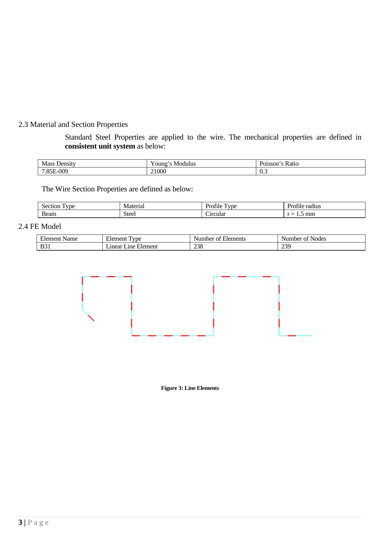
2.4 FE Model
Element Name Element Type Number of Elements Number of Nodes
B31 Linear Line Element 238 239
Figure 3: Line Elements
3 | P a g e
⊘ This is a preview!⊘
Do you want full access?
Subscribe today to unlock all pages.

Trusted by 1+ million students worldwide
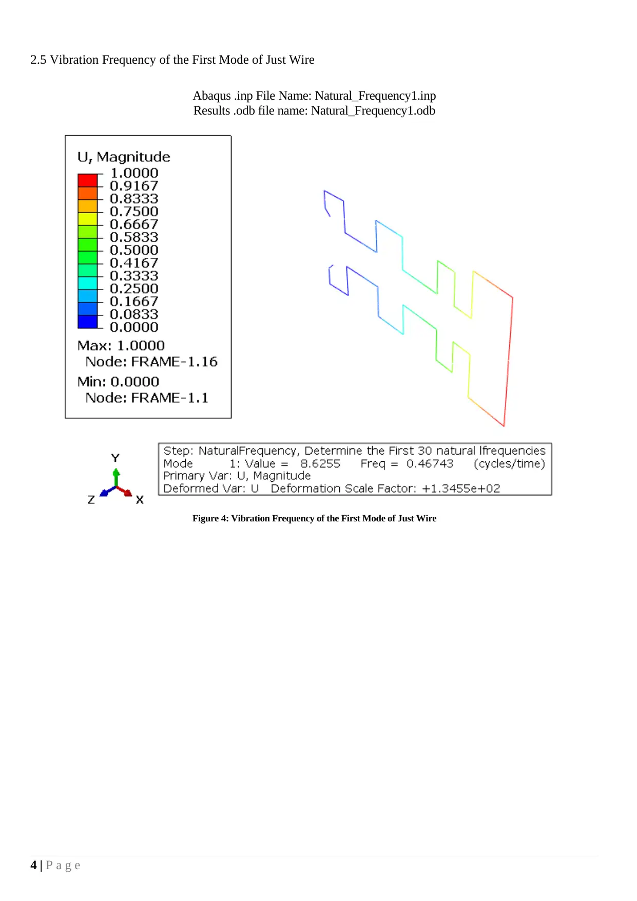
2.5 Vibration Frequency of the First Mode of Just Wire
Abaqus .inp File Name: Natural_Frequency1.inp
Results .odb file name: Natural_Frequency1.odb
Figure 4: Vibration Frequency of the First Mode of Just Wire
4 | P a g e
Abaqus .inp File Name: Natural_Frequency1.inp
Results .odb file name: Natural_Frequency1.odb
Figure 4: Vibration Frequency of the First Mode of Just Wire
4 | P a g e
Paraphrase This Document
Need a fresh take? Get an instant paraphrase of this document with our AI Paraphraser
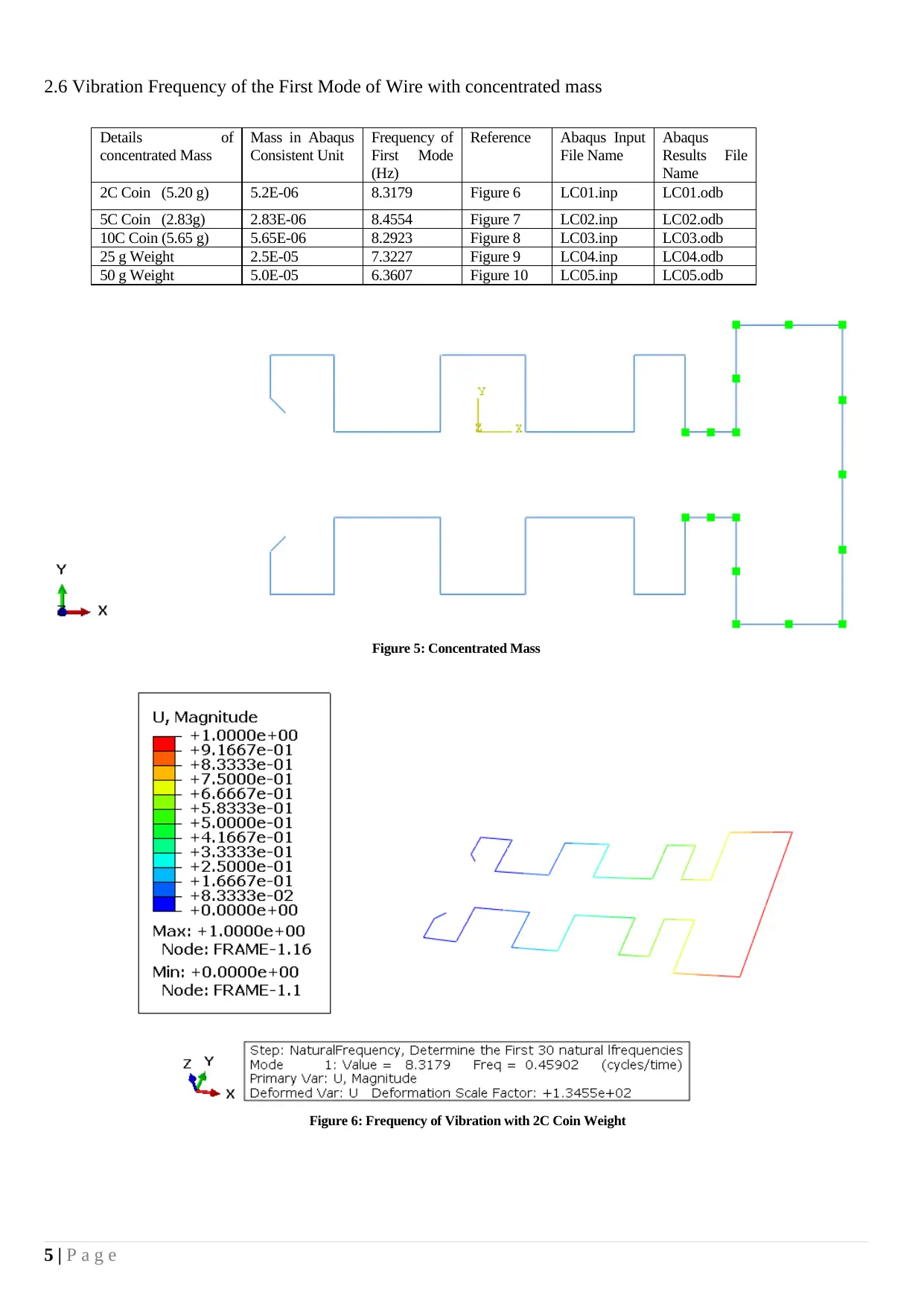
2.6 Vibration Frequency of the First Mode of Wire with concentrated mass
Details of
concentrated Mass
Mass in Abaqus
Consistent Unit
Frequency of
First Mode
(Hz)
Reference Abaqus Input
File Name
Abaqus
Results File
Name
2C Coin (5.20 g) 5.2E-06 8.3179 Figure 6 LC01.inp LC01.odb
5C Coin (2.83g) 2.83E-06 8.4554 Figure 7 LC02.inp LC02.odb
10C Coin (5.65 g) 5.65E-06 8.2923 Figure 8 LC03.inp LC03.odb
25 g Weight 2.5E-05 7.3227 Figure 9 LC04.inp LC04.odb
50 g Weight 5.0E-05 6.3607 Figure 10 LC05.inp LC05.odb
Figure 5: Concentrated Mass
5 | P a g e
Figure 6: Frequency of Vibration with 2C Coin Weight
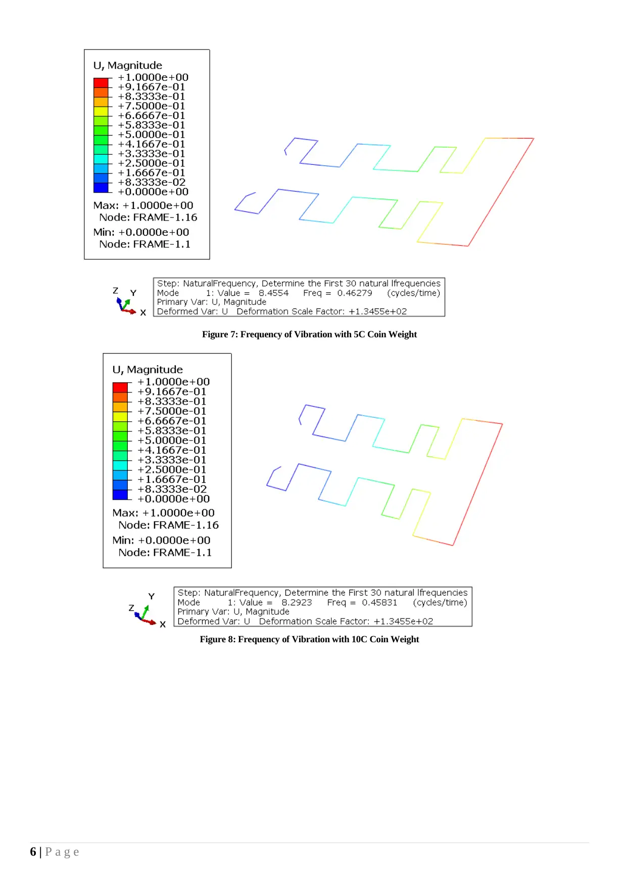
Figure 7: Frequency of Vibration with 5C Coin Weight
Figure 8: Frequency of Vibration with 10C Coin Weight
6 | P a g e
Figure 8: Frequency of Vibration with 10C Coin Weight
6 | P a g e
⊘ This is a preview!⊘
Do you want full access?
Subscribe today to unlock all pages.

Trusted by 1+ million students worldwide
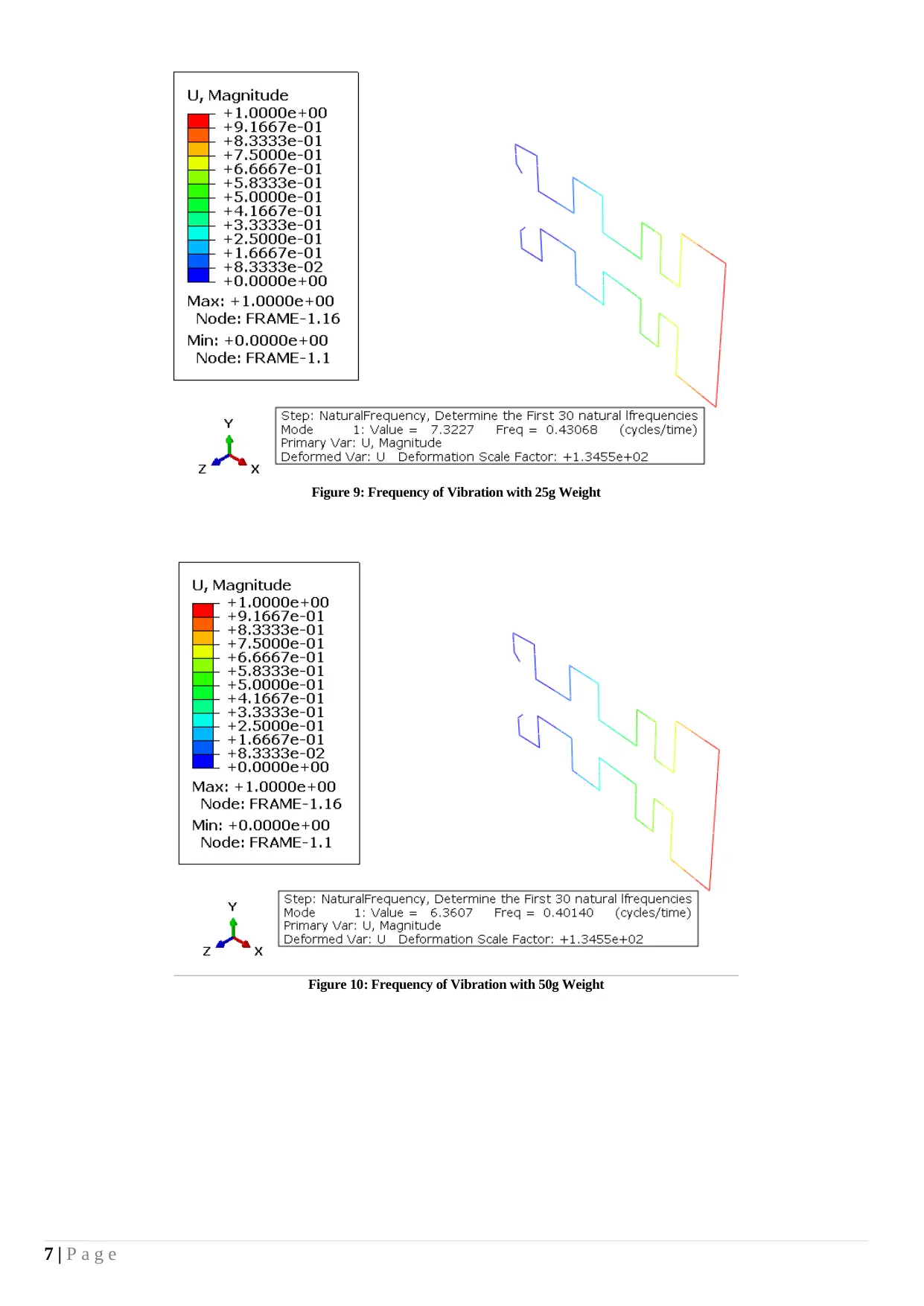
Figure 9: Frequency of Vibration with 25g Weight
Figure 10: Frequency of Vibration with 50g Weight
7 | P a g e
Figure 10: Frequency of Vibration with 50g Weight
7 | P a g e
Paraphrase This Document
Need a fresh take? Get an instant paraphrase of this document with our AI Paraphraser
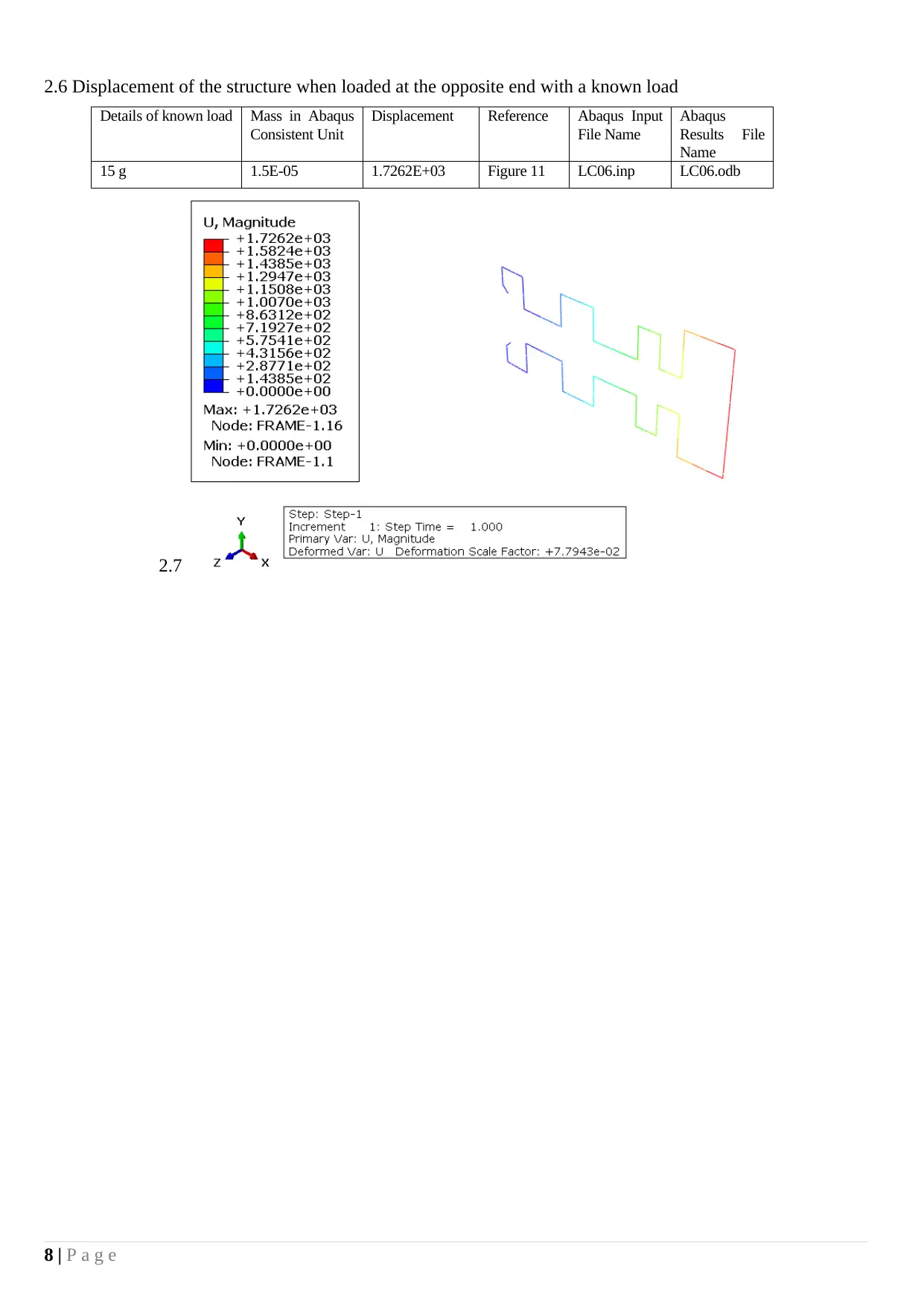
2.6 Displacement of the structure when loaded at the opposite end with a known load
Details of known load Mass in Abaqus
Consistent Unit
Displacement Reference Abaqus Input
File Name
Abaqus
Results File
Name
15 g 1.5E-05 1.7262E+03 Figure 11 LC06.inp LC06.odb
2.7
8 | P a g e
Details of known load Mass in Abaqus
Consistent Unit
Displacement Reference Abaqus Input
File Name
Abaqus
Results File
Name
15 g 1.5E-05 1.7262E+03 Figure 11 LC06.inp LC06.odb
2.7
8 | P a g e
Conclusion
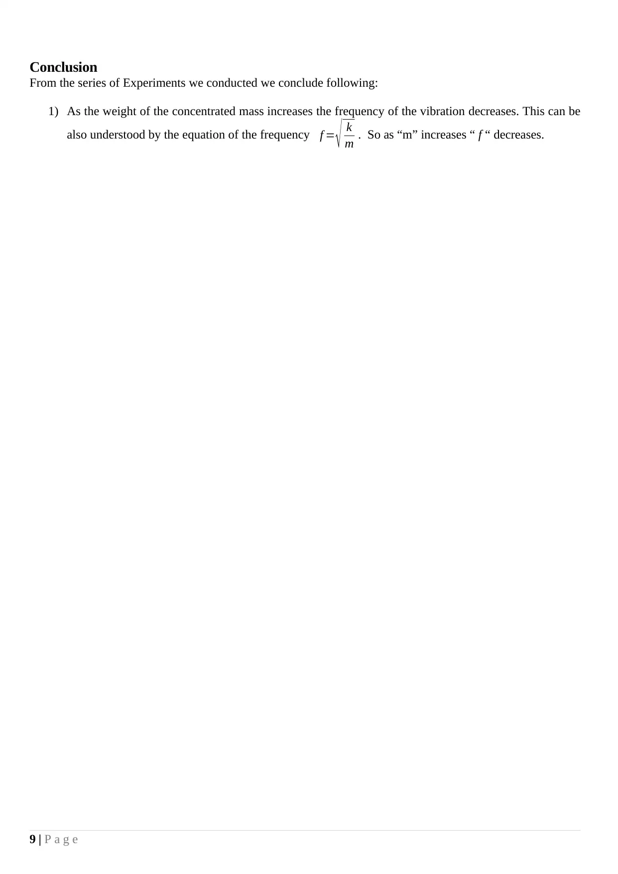
From the series of Experiments we conducted we conclude following:
1) As the weight of the concentrated mass increases the frequency of the vibration decreases. This can be
also understood by the equation of the frequency f = √ k
m . So as “m” increases “ f “ decreases.
9 | P a g e
From the series of Experiments we conducted we conclude following:
1) As the weight of the concentrated mass increases the frequency of the vibration decreases. This can be
also understood by the equation of the frequency f = √ k
m . So as “m” increases “ f “ decreases.
9 | P a g e
⊘ This is a preview!⊘
Do you want full access?
Subscribe today to unlock all pages.

Trusted by 1+ million students worldwide
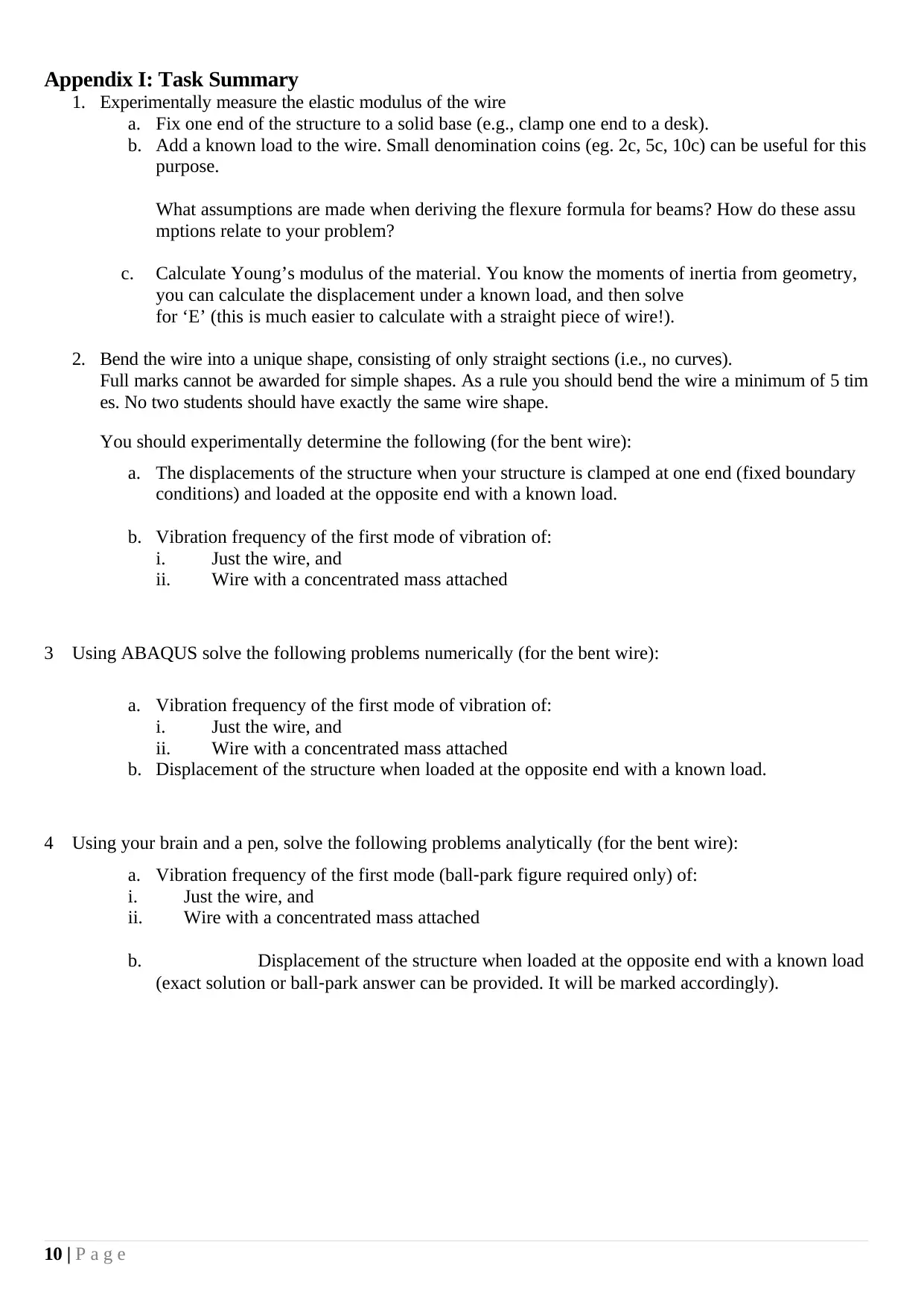
Appendix I: Task Summary
1. Experimentally measure the elastic modulus of the wire
a. Fix one end of the structure to a solid base (e.g., clamp one end to a desk).
b. Add a known load to the wire. Small denomination coins (eg. 2c, 5c, 10c) can be useful for this
purpose.
What assumptions are made when deriving the flexure formula for beams? How do these assu
mptions relate to your problem?
c. Calculate Young’s modulus of the material. You know the moments of inertia from geometry,
you can calculate the displacement under a known load, and then solve
for ‘E’ (this is much easier to calculate with a straight piece of wire!).
2. Bend the wire into a unique shape, consisting of only straight sections (i.e., no curves).
Full marks cannot be awarded for simple shapes. As a rule you should bend the wire a minimum of 5 tim
es. No two students should have exactly the same wire shape.
You should experimentally determine the following (for the bent wire):
a. The displacements of the structure when your structure is clamped at one end (fixed boundary
conditions) and loaded at the opposite end with a known load.
b. Vibration frequency of the first mode of vibration of:
i. Just the wire, and
ii. Wire with a concentrated mass attached
3 Using ABAQUS solve the following problems numerically (for the bent wire):
a. Vibration frequency of the first mode of vibration of:
i. Just the wire, and
ii. Wire with a concentrated mass attached
b. Displacement of the structure when loaded at the opposite end with a known load.
4 Using your brain and a pen, solve the following problems analytically (for the bent wire):
a. Vibration frequency of the first mode (ball‐park figure required only) of:
i. Just the wire, and
ii. Wire with a concentrated mass attached
b. Displacement of the structure when loaded at the opposite end with a known load
(exact solution or ball‐park answer can be provided. It will be marked accordingly).
10 | P a g e
Paraphrase This Document
Need a fresh take? Get an instant paraphrase of this document with our AI Paraphraser
Appendix II: Modal Analysis Theory [3]
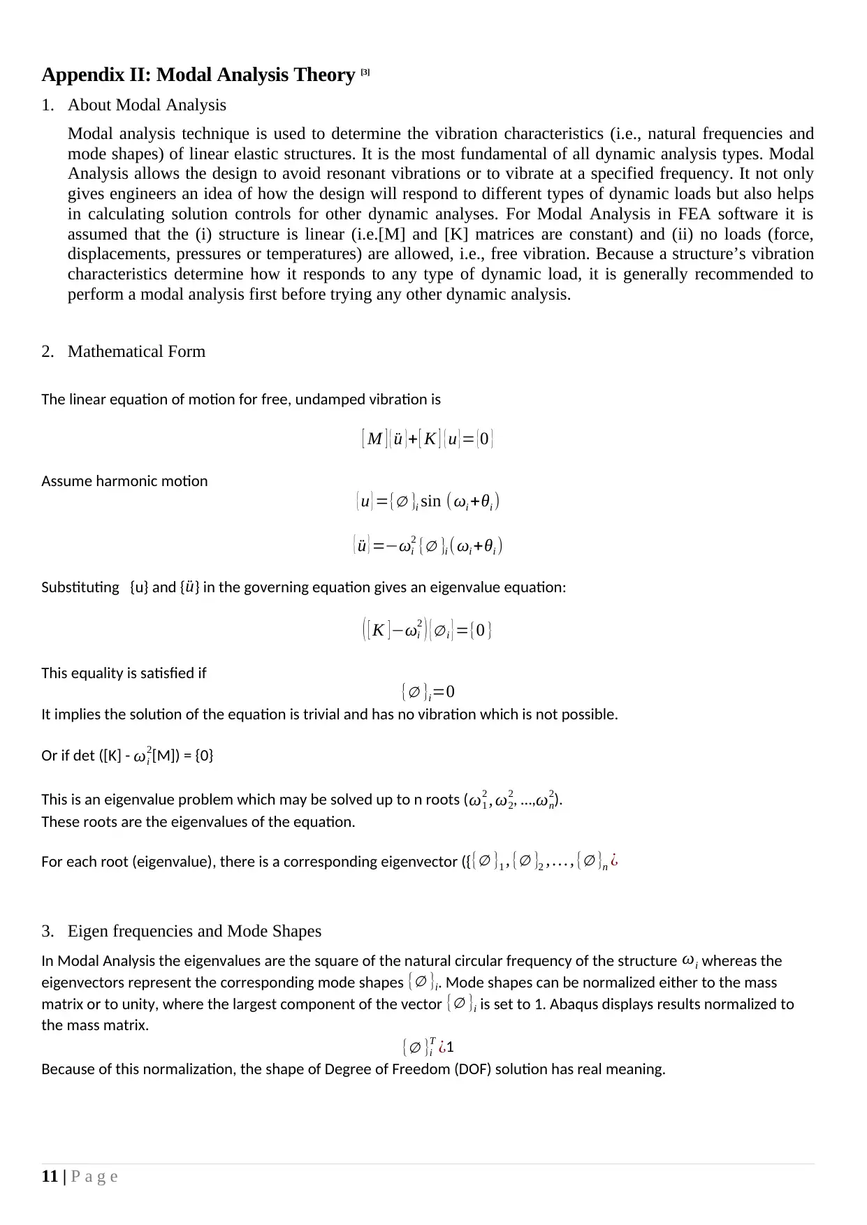
1. About Modal Analysis
Modal analysis technique is used to determine the vibration characteristics (i.e., natural frequencies and
mode shapes) of linear elastic structures. It is the most fundamental of all dynamic analysis types. Modal
Analysis allows the design to avoid resonant vibrations or to vibrate at a specified frequency. It not only
gives engineers an idea of how the design will respond to different types of dynamic loads but also helps
in calculating solution controls for other dynamic analyses. For Modal Analysis in FEA software it is
assumed that the (i) structure is linear (i.e.[M] and [K] matrices are constant) and (ii) no loads (force,
displacements, pressures or temperatures) are allowed, i.e., free vibration. Because a structure’s vibration
characteristics determine how it responds to any type of dynamic load, it is generally recommended to
perform a modal analysis first before trying any other dynamic analysis.
2. Mathematical Form
The linear equation of motion for free, undamped vibration is
[ M ] { ¨u }+ [ K ] { u }= {0 }
Assume harmonic motion
{ u } ={∅ }i sin ( ωi +θi )
{ ¨u } =−ωi
2 {∅ }i ( ωi +θi )
Substituting {u} and { ¨u} in the governing equation gives an eigenvalue equation:
( [ K ] −ωi
2 ) { ∅ i } ={0 }
This equality is satisfied if
{∅ }i=0
It implies the solution of the equation is trivial and has no vibration which is not possible.
Or if det ([K] - ωi
2[M]) = {0}
This is an eigenvalue problem which may be solved up to n roots ( ω1
2 , ω2
2, …,ωn
2).
These roots are the eigenvalues of the equation.
For each root (eigenvalue), there is a corresponding eigenvector ({{∅ }1 , {∅ }2 , … , {∅ }n ¿
3. Eigen frequencies and Mode Shapes
In Modal Analysis the eigenvalues are the square of the natural circular frequency of the structure ωi whereas the
eigenvectors represent the corresponding mode shapes {∅ }i. Mode shapes can be normalized either to the mass
matrix or to unity, where the largest component of the vector {∅ }i is set to 1. Abaqus displays results normalized to
the mass matrix.
{∅ }i
T ¿1
Because of this normalization, the shape of Degree of Freedom (DOF) solution has real meaning.
11 | P a g e
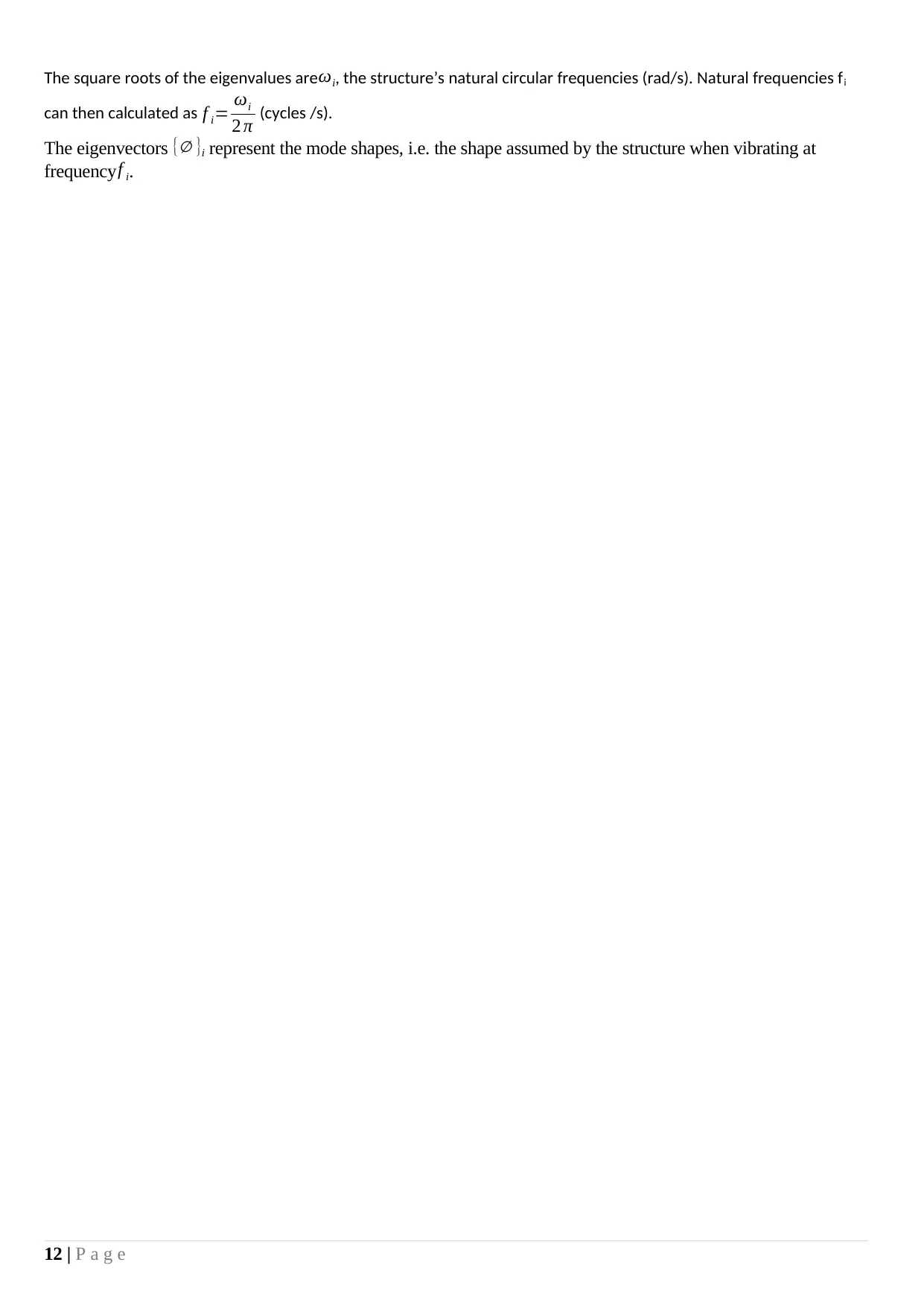
The square roots of the eigenvalues are ωi, the structure’s natural circular frequencies (rad/s). Natural frequencies fi
can then calculated as f i= ωi
2 π (cycles /s).
The eigenvectors {∅ }i represent the mode shapes, i.e. the shape assumed by the structure when vibrating at
frequency f i.
12 | P a g e
can then calculated as f i= ωi
2 π (cycles /s).
The eigenvectors {∅ }i represent the mode shapes, i.e. the shape assumed by the structure when vibrating at
frequency f i.
12 | P a g e
⊘ This is a preview!⊘
Do you want full access?
Subscribe today to unlock all pages.

Trusted by 1+ million students worldwide
1 out of 13
Related Documents
Your All-in-One AI-Powered Toolkit for Academic Success.
+13062052269
info@desklib.com
Available 24*7 on WhatsApp / Email
![[object Object]](/_next/static/media/star-bottom.7253800d.svg)
Unlock your academic potential
Copyright © 2020–2025 A2Z Services. All Rights Reserved. Developed and managed by ZUCOL.


