University Report: Modelling Enterprise Architectures for Valentinos
VerifiedAdded on 2023/01/12
|13
|1013
|47
Report
AI Summary
This report delves into the modeling of enterprise architectures, focusing on the "Valentinos" personal introduction agency. The report provides an in-depth analysis using various UML diagrams, including an activity diagram with swim-lanes and transitions, and sequence diagrams representing four prototypes. A class diagram is also included, which is then utilized to develop an entity-relationship diagram. The report also includes a data dictionary to define the entities and attributes. The Zachman Framework is also used to analyze the data. The report offers a comprehensive overview of the agency's structure and functions through the use of these architectural models.
Modelling Enterprise Architectures
1
1
Paraphrase This Document
Need a fresh take? Get an instant paraphrase of this document with our AI Paraphraser
Contents
INTRODUCTION...........................................................................................................................3
TASKS.............................................................................................................................................3
CONCLUSION..............................................................................................................................12
REFERENCES..............................................................................................................................13
2
INTRODUCTION
The modelling architecture is a type of scale model which mainly representation of overall
structure and built to study aspects of communication design. It is mainly depending on the
purpose where how enterprise further perform different operations and functions. The report is
mainly focused on the “Valentinos” which become successful “personal introduction agency”.
The report will describe about the activity diagram that mainly including swim-lanes and
transitions. It will produce sequence diagram that consists of four prototypes and also consider
class diagram to develop entity relationship diagram.
TASKS
1). Consider use case diagram to produce overall activity diagram which including transitions
and swim-lanes.
Activity diagram:
It is defined as UML diagram that mainly focused on the execution and flow of behavior
within system instead of implementing task. It is also known as object-oriented flowchart which
mainly consists of activities. It enabled for maintaining and controlling activities that are made
up of action, apply as per behavioral modeling technique (Filipova and Nikiforova, 2019).
An activity diagram is basically control flow of information from start point to finish
point in different decision aspects. It also depicts concurrent as well as sequential processing.
According to scenario, Activity diagram is used in the business process modelling which easily
handle large number of information effectively and efficiently.
3
⊘ This is a preview!⊘
Do you want full access?
Subscribe today to unlock all pages.

Trusted by 1+ million students worldwide
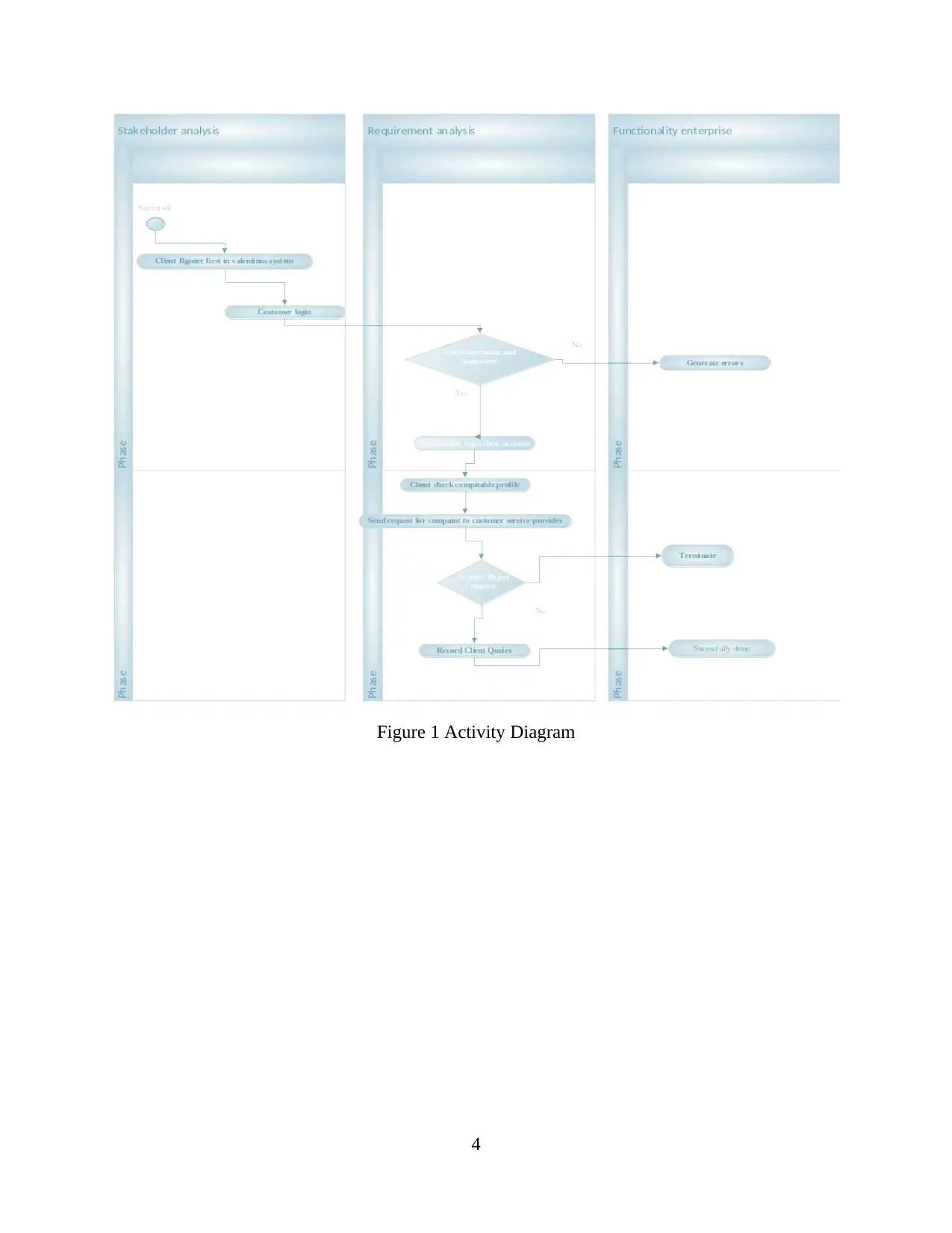
Figure 1 Activity Diagram
4
4
Paraphrase This Document
Need a fresh take? Get an instant paraphrase of this document with our AI Paraphraser
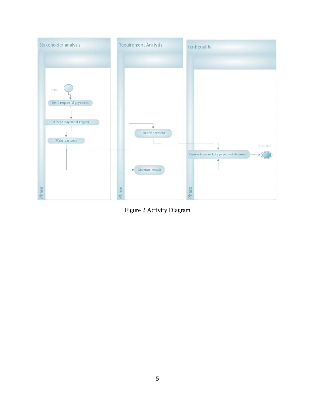
Figure 2 Activity Diagram
5
5
3). Design 4 Sequence diagrams and corresponding to four prototypes.
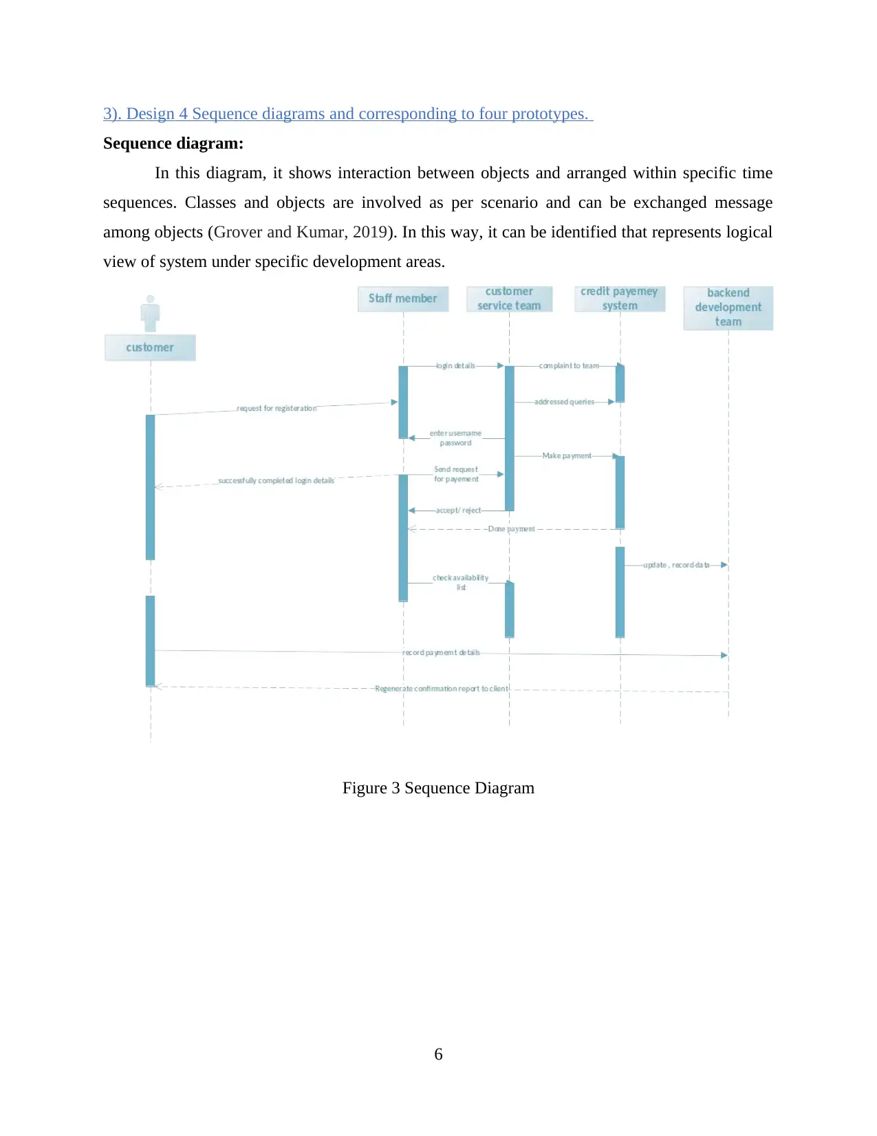
Sequence diagram:
In this diagram, it shows interaction between objects and arranged within specific time
sequences. Classes and objects are involved as per scenario and can be exchanged message
among objects (Grover and Kumar, 2019). In this way, it can be identified that represents logical
view of system under specific development areas.
Figure 3 Sequence Diagram
6
⊘ This is a preview!⊘
Do you want full access?
Subscribe today to unlock all pages.

Trusted by 1+ million students worldwide
4). Redraw class diagram and consider existing class diagram from state-chart.
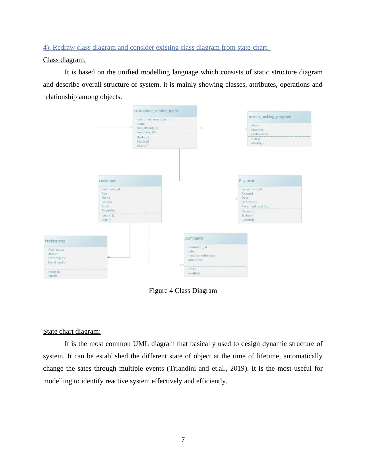
Class diagram:
It is based on the unified modelling language which consists of static structure diagram
and describe overall structure of system. it is mainly showing classes, attributes, operations and
relationship among objects.
Figure 4 Class Diagram
State chart diagram:
It is the most common UML diagram that basically used to design dynamic structure of
system. It can be established the different state of object at the time of lifetime, automatically
change the sates through multiple events (Triandini and et.al., 2019). It is the most useful for
modelling to identify reactive system effectively and efficiently.
7
Paraphrase This Document
Need a fresh take? Get an instant paraphrase of this document with our AI Paraphraser
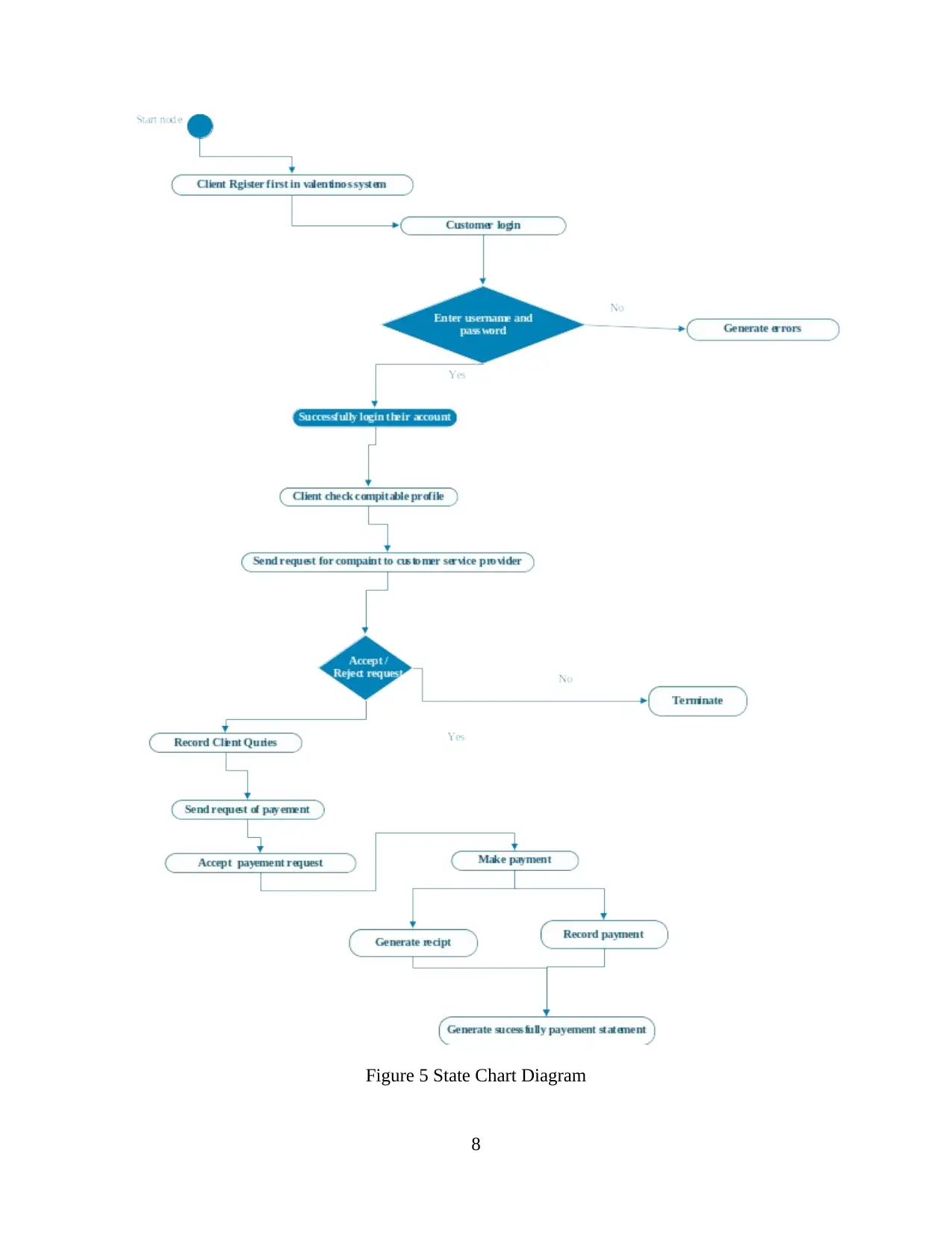
Figure 5 State Chart Diagram
8
8
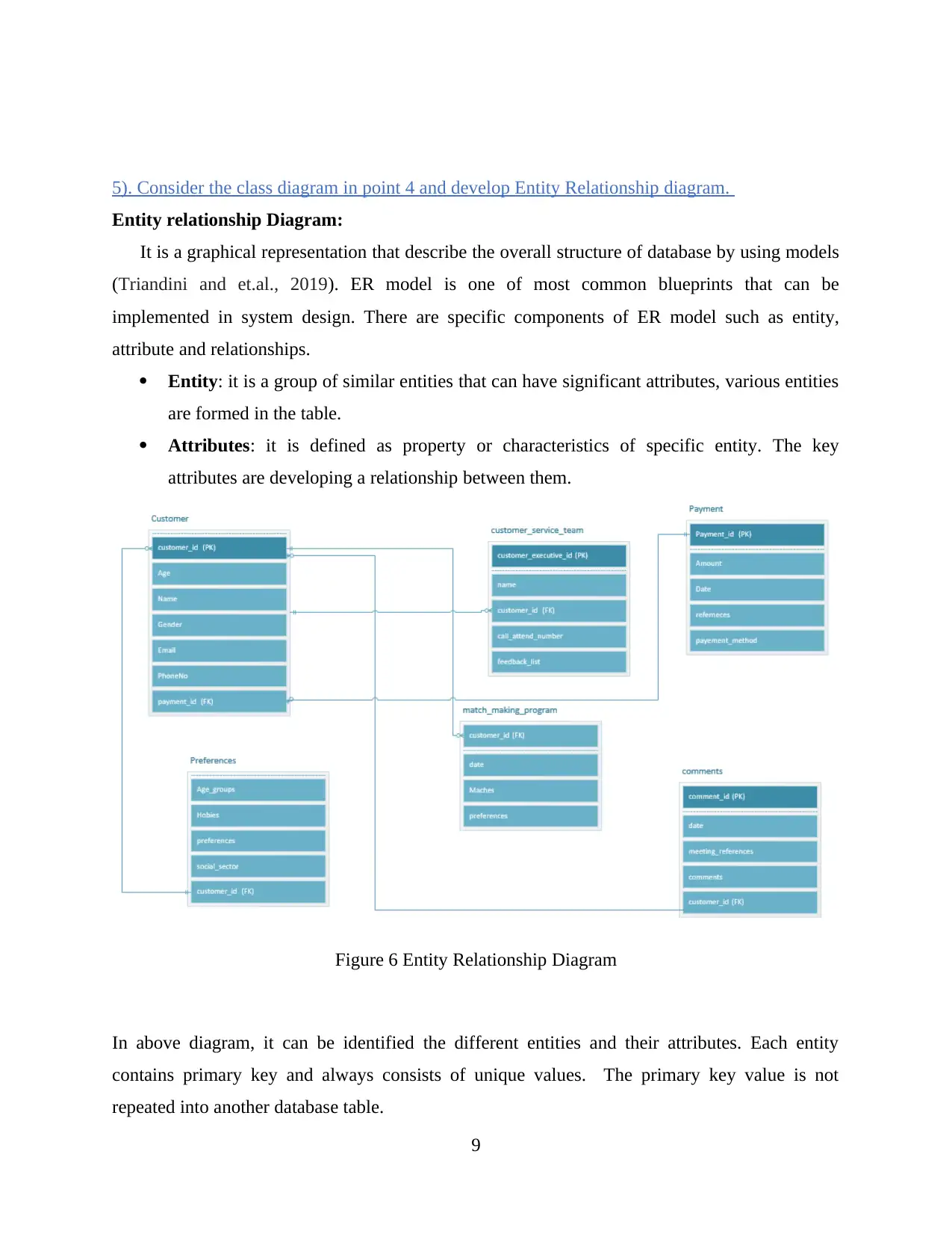
5). Consider the class diagram in point 4 and develop Entity Relationship diagram.
Entity relationship Diagram:
It is a graphical representation that describe the overall structure of database by using models
(Triandini and et.al., 2019). ER model is one of most common blueprints that can be
implemented in system design. There are specific components of ER model such as entity,
attribute and relationships.
Entity: it is a group of similar entities that can have significant attributes, various entities
are formed in the table.
Attributes: it is defined as property or characteristics of specific entity. The key
attributes are developing a relationship between them.
Figure 6 Entity Relationship Diagram
In above diagram, it can be identified the different entities and their attributes. Each entity
contains primary key and always consists of unique values. The primary key value is not
repeated into another database table.
9
⊘ This is a preview!⊘
Do you want full access?
Subscribe today to unlock all pages.

Trusted by 1+ million students worldwide
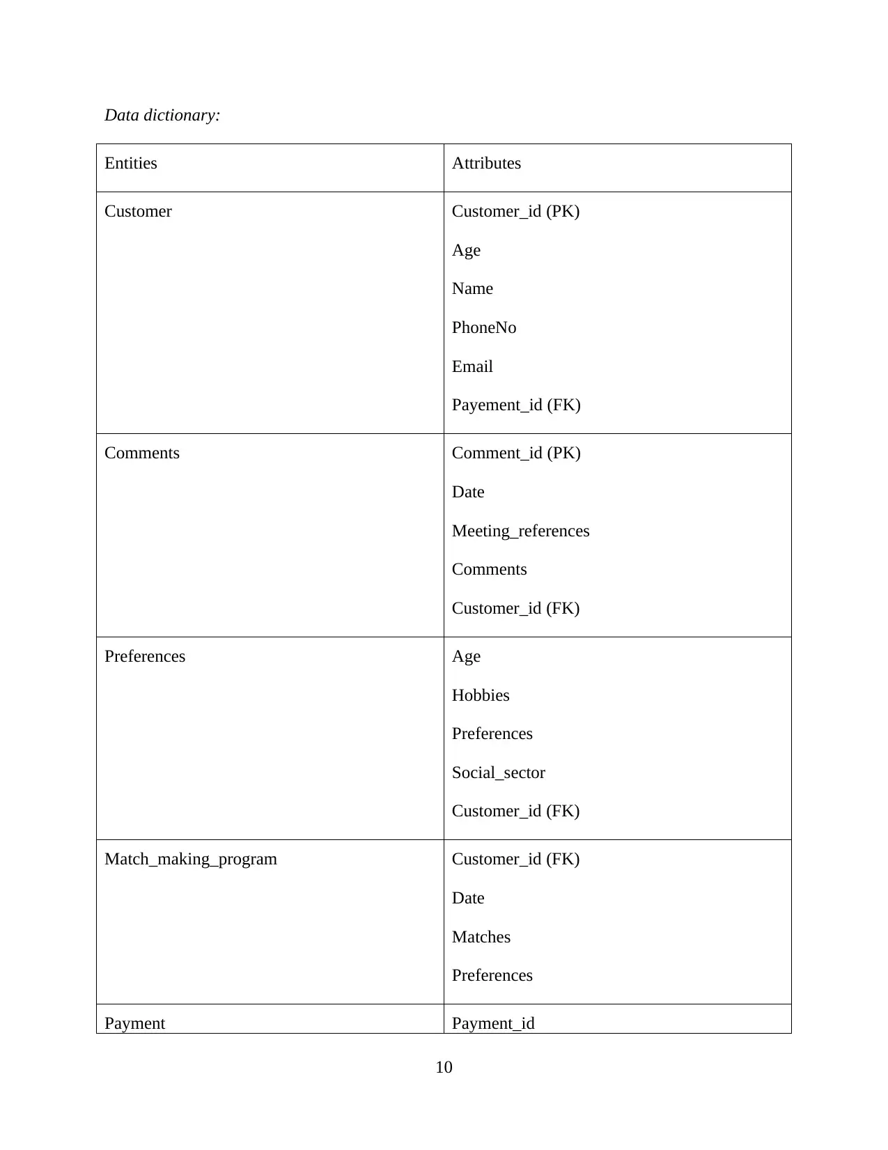
Data dictionary:
Entities Attributes
Customer Customer_id (PK)
Age
Name
PhoneNo
Email
Payement_id (FK)
Comments Comment_id (PK)
Date
Meeting_references
Comments
Customer_id (FK)
Preferences Age
Hobbies
Preferences
Social_sector
Customer_id (FK)
Match_making_program Customer_id (FK)
Date
Matches
Preferences
Payment Payment_id
10
Entities Attributes
Customer Customer_id (PK)
Age
Name
PhoneNo
Payement_id (FK)
Comments Comment_id (PK)
Date
Meeting_references
Comments
Customer_id (FK)
Preferences Age
Hobbies
Preferences
Social_sector
Customer_id (FK)
Match_making_program Customer_id (FK)
Date
Matches
Preferences
Payment Payment_id
10
Paraphrase This Document
Need a fresh take? Get an instant paraphrase of this document with our AI Paraphraser
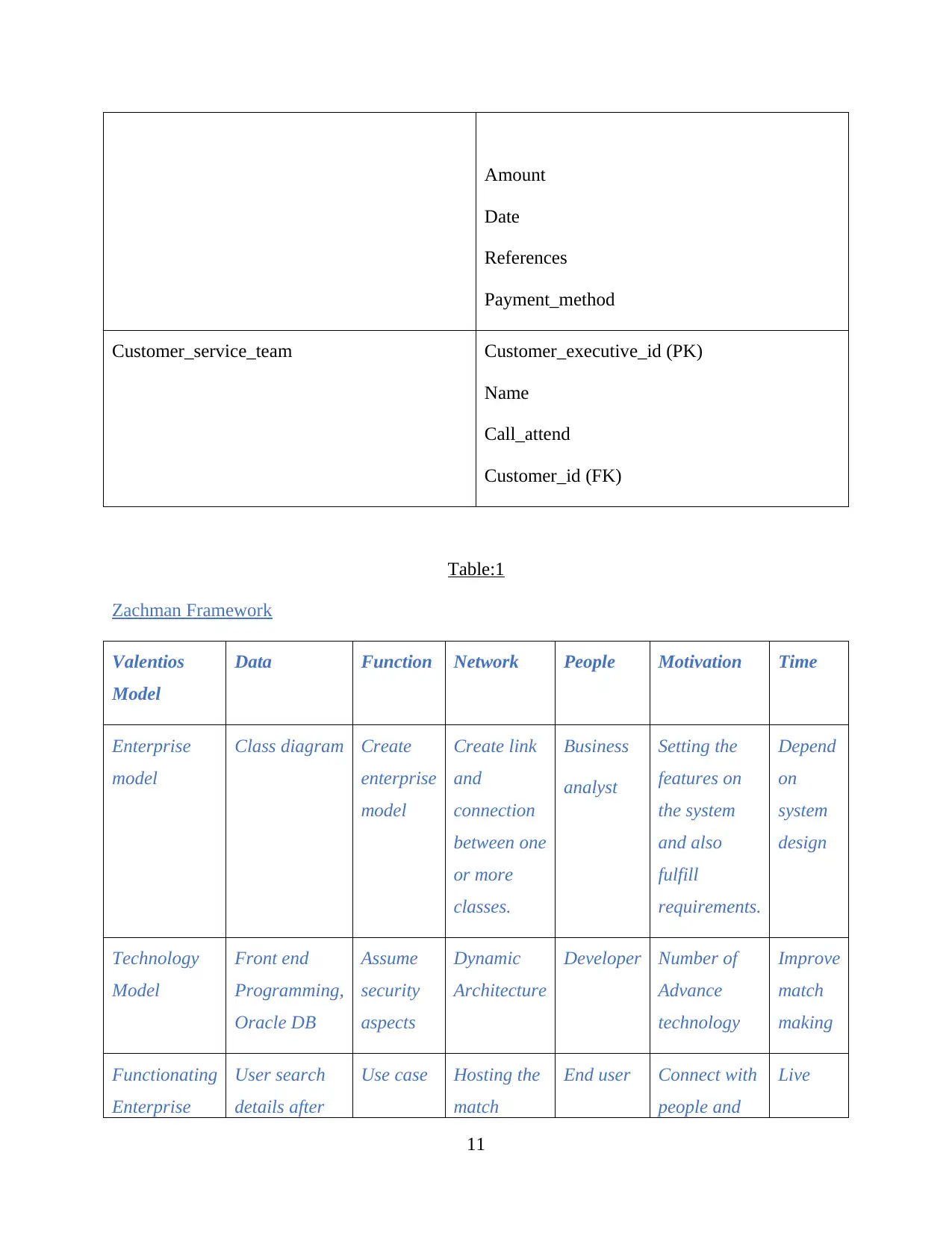
Amount
Date
References
Payment_method
Customer_service_team Customer_executive_id (PK)
Name
Call_attend
Customer_id (FK)
Table:1
Zachman Framework
Valentios
Model
Data Function Network People Motivation Time
Enterprise
model
Class diagram Create
enterprise
model
Create link
and
connection
between one
or more
classes.
Business
analyst
Setting the
features on
the system
and also
fulfill
requirements.
Depend
on
system
design
Technology
Model
Front end
Programming,
Oracle DB
Assume
security
aspects
Dynamic
Architecture
Developer Number of
Advance
technology
Improve
match
making
Functionating
Enterprise
User search
details after
Use case Hosting the
match
End user Connect with
people and
Live
11
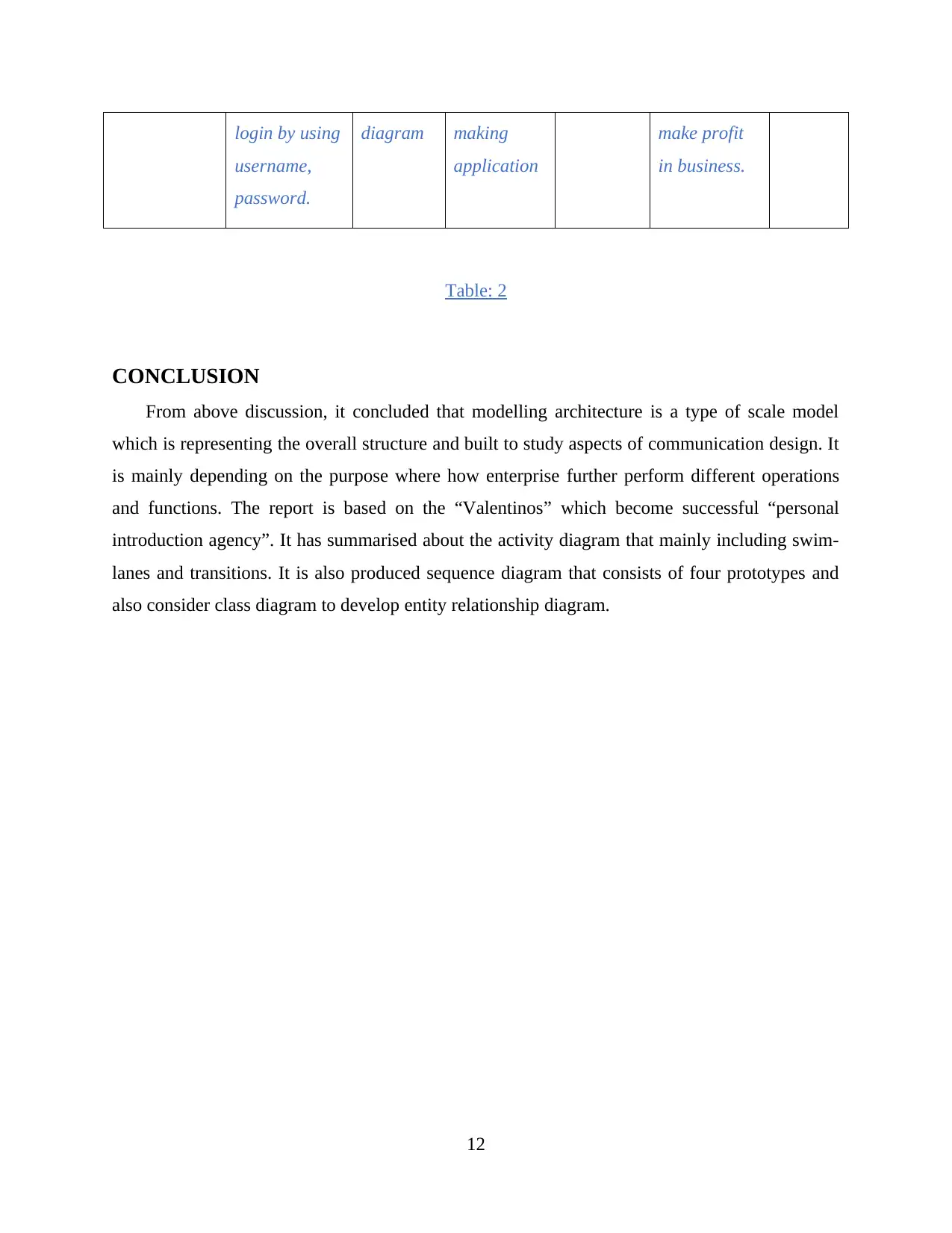
login by using
username,
password.
diagram making
application
make profit
in business.
Table: 2
CONCLUSION
From above discussion, it concluded that modelling architecture is a type of scale model
which is representing the overall structure and built to study aspects of communication design. It
is mainly depending on the purpose where how enterprise further perform different operations
and functions. The report is based on the “Valentinos” which become successful “personal
introduction agency”. It has summarised about the activity diagram that mainly including swim-
lanes and transitions. It is also produced sequence diagram that consists of four prototypes and
also consider class diagram to develop entity relationship diagram.
12
⊘ This is a preview!⊘
Do you want full access?
Subscribe today to unlock all pages.

Trusted by 1+ million students worldwide
1 out of 13