Modulation and Demodulation
Added on 2022-09-06
40 Pages5303 Words25 Views
Modulation and Demodulation 1
ABSTRACT.
In this report, Amplitude modulation demodulation, AM, have been dealt in details. The
theoretical background of the AM in comparison with other types of modulation ranging from
analogue to digital have been analyzed. In the Matlab Simulink environment, AM modulation
demodulation types have been implemented. In the first stage, Double Side Side Band with the
Carrier, DSB WC, AM modulation have been designed in Simulink and the modulated output
signals tested under different modulating index. The analysis of the output signals was derived
from the equivalent signals in continuous time and frequency domain. Second stage involves
demodulation of the DSB WC modulated signals were implemented in Matlab Simulink
applying the principle of envelope detector and coherent synchronous detector. The resultant
output message signals at the receiving end in both cases were compared with the actual message
at the sending end. In the last stage, the phase and frequency of the local oscillator in the
synchronous detector was altered in accordance with the given parameters and the effects on the
resultant demodulated signals were analyzed in the Matlab Simulink environment.
1: INTRODUCTION
Advancement and revolution in technology has resulted to a number of inventions that has
reduced vast global into a small nation as far as information transmission in concerned. For
instance, in 1876, Graham Bell invented transmission of voice message using electrical signals
(Encyclopedia.com, 2019). Wireless transmission medium that uses electromagnetic waves was
invented to curb limited of hardwired system. Electromagnetic transmission, commonly dubbed
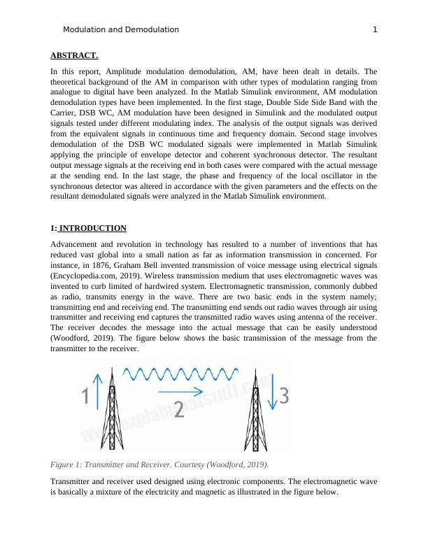
as radio, transmits energy in the wave. There are two basic ends in the system namely;
transmitting end and receiving end. The transmitting end sends out radio waves through air using
transmitter and receiving end captures the transmitted radio waves using antenna of the receiver.
The receiver decodes the message into the actual message that can be easily understood
(Woodford, 2019). The figure below shows the basic transmission of the message from the
transmitter to the receiver.
Figure 1: Transmitter and Receiver. Courtesy (Woodford, 2019).
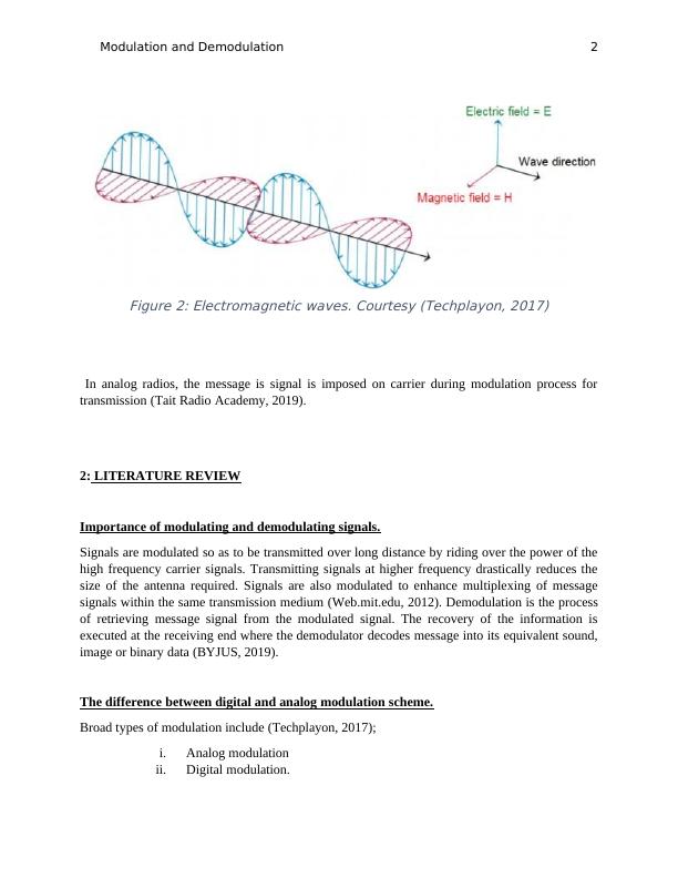
Transmitter and receiver used designed using electronic components. The electromagnetic wave
is basically a mixture of the electricity and magnetic as illustrated in the figure below.
ABSTRACT.
In this report, Amplitude modulation demodulation, AM, have been dealt in details. The
theoretical background of the AM in comparison with other types of modulation ranging from
analogue to digital have been analyzed. In the Matlab Simulink environment, AM modulation
demodulation types have been implemented. In the first stage, Double Side Side Band with the
Carrier, DSB WC, AM modulation have been designed in Simulink and the modulated output
signals tested under different modulating index. The analysis of the output signals was derived
from the equivalent signals in continuous time and frequency domain. Second stage involves
demodulation of the DSB WC modulated signals were implemented in Matlab Simulink
applying the principle of envelope detector and coherent synchronous detector. The resultant
output message signals at the receiving end in both cases were compared with the actual message
at the sending end. In the last stage, the phase and frequency of the local oscillator in the
synchronous detector was altered in accordance with the given parameters and the effects on the
resultant demodulated signals were analyzed in the Matlab Simulink environment.
1: INTRODUCTION
Advancement and revolution in technology has resulted to a number of inventions that has
reduced vast global into a small nation as far as information transmission in concerned. For
instance, in 1876, Graham Bell invented transmission of voice message using electrical signals
(Encyclopedia.com, 2019). Wireless transmission medium that uses electromagnetic waves was
invented to curb limited of hardwired system. Electromagnetic transmission, commonly dubbed
as radio, transmits energy in the wave. There are two basic ends in the system namely;
transmitting end and receiving end. The transmitting end sends out radio waves through air using
transmitter and receiving end captures the transmitted radio waves using antenna of the receiver.
The receiver decodes the message into the actual message that can be easily understood
(Woodford, 2019). The figure below shows the basic transmission of the message from the
transmitter to the receiver.
Figure 1: Transmitter and Receiver. Courtesy (Woodford, 2019).
Transmitter and receiver used designed using electronic components. The electromagnetic wave
is basically a mixture of the electricity and magnetic as illustrated in the figure below.
Modulation and Demodulation 2
Figure 2: Electromagnetic waves. Courtesy (Techplayon, 2017)
In analog radios, the message is signal is imposed on carrier during modulation process for
transmission (Tait Radio Academy, 2019).
2: LITERATURE REVIEW
Importance of modulating and demodulating signals.
Signals are modulated so as to be transmitted over long distance by riding over the power of the
high frequency carrier signals. Transmitting signals at higher frequency drastically reduces the
size of the antenna required. Signals are also modulated to enhance multiplexing of message
signals within the same transmission medium (Web.mit.edu, 2012). Demodulation is the process
of retrieving message signal from the modulated signal. The recovery of the information is
executed at the receiving end where the demodulator decodes message into its equivalent sound,
image or binary data (BYJUS, 2019).
The difference between digital and analog modulation scheme.
Broad types of modulation include (Techplayon, 2017);
i. Analog modulation
ii. Digital modulation.
Modulation and Demodulation 3
Analog modulation involves transmission of the analog baseband low frequency message signal
using high frequency carrier signals (Spincore.com, 2019).
Types of analog modulation includes (BYJUS, 2019);
i. Frequency modulation
ii. Amplitude modulation
iii. Phase modulation
The digital modulation uses discrete message signal to modulate high frequency carrier signal
(Global, 2019).
Types of digital digital modulation includes;
i. Amplitude Shift Keying ASK
ii. Frequency Shift Keying FSK
iii. Phase Shift Keying PSK
In many aspects, analog modulation is dissimilar to digital modulation. In the analog modulation,
the signal is continuous while in the digital modulation, the signal is given as a set of discrete
values. The input data signal for digital modulation must be in binary numbers 1s and 0s as
opposed to the analog signal whose maximum and minimum values of the amplitude is
considered (ElProCus, 2019).
Theoretical performance of the digital modulation.
Types of digital modulation are discussed below.
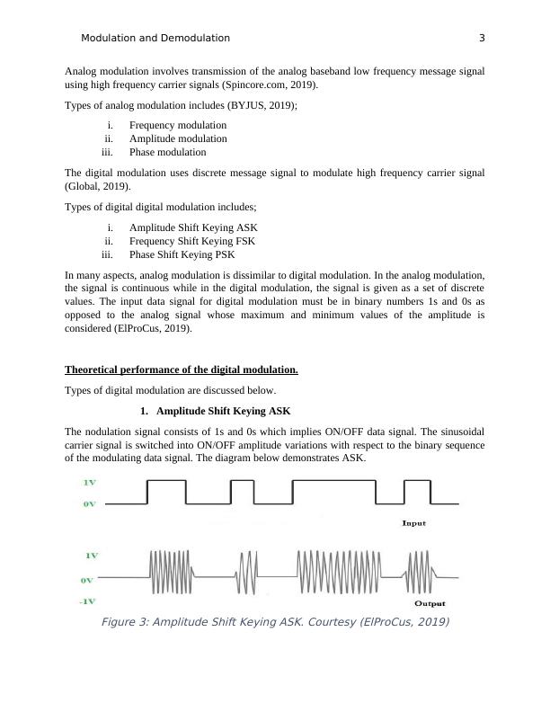
1. Amplitude Shift Keying ASK
The nodulation signal consists of 1s and 0s which implies ON/OFF data signal. The sinusoidal
carrier signal is switched into ON/OFF amplitude variations with respect to the binary sequence
of the modulating data signal. The diagram below demonstrates ASK.
Figure 3: Amplitude Shift Keying ASK. Courtesy (ElProCus, 2019)
Analog modulation involves transmission of the analog baseband low frequency message signal
using high frequency carrier signals (Spincore.com, 2019).
Types of analog modulation includes (BYJUS, 2019);
i. Frequency modulation
ii. Amplitude modulation
iii. Phase modulation
The digital modulation uses discrete message signal to modulate high frequency carrier signal
(Global, 2019).
Types of digital digital modulation includes;
i. Amplitude Shift Keying ASK
ii. Frequency Shift Keying FSK
iii. Phase Shift Keying PSK
In many aspects, analog modulation is dissimilar to digital modulation. In the analog modulation,
the signal is continuous while in the digital modulation, the signal is given as a set of discrete
values. The input data signal for digital modulation must be in binary numbers 1s and 0s as
opposed to the analog signal whose maximum and minimum values of the amplitude is
considered (ElProCus, 2019).
Theoretical performance of the digital modulation.
Types of digital modulation are discussed below.
1. Amplitude Shift Keying ASK
The nodulation signal consists of 1s and 0s which implies ON/OFF data signal. The sinusoidal
carrier signal is switched into ON/OFF amplitude variations with respect to the binary sequence
of the modulating data signal. The diagram below demonstrates ASK.
Figure 3: Amplitude Shift Keying ASK. Courtesy (ElProCus, 2019)
Modulation and Demodulation 4
ASK is applied in the IR remote control and in the transmitters and receivers of the fiber optic.
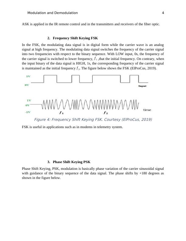
2. Frequency Shift Keying FSK
In the FSK, the modulating data signal is in digital form while the carrier wave is an analog
signal at high frequency. The modulating data signal switches the frequency of the carrier signal
into two frequencies with respect to the binary sequence. With LOW input, 0s, the frequency of
the carrier signal is switched to lower frequency, f 1 ,that the initial frequency. On contrary, when
the input binary of the data signal is HIGH, 1s, the corresponding frequency of the carrier signal
is maintained as the initial frequency f 2. The figure below shows the FSK (ElProCus, 2019).
Figure 4: Frequency Shift Keying FSK. Courtesy (ElProCus, 2019)
FSK is useful in applications such as in modems in telemetry system.
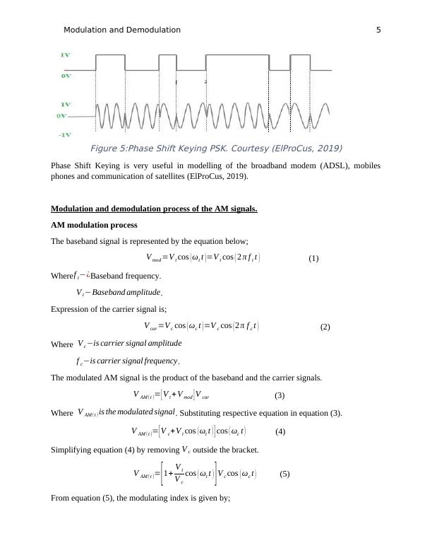
3. Phase Shift Keying PSK
Phase Shift Keying, PSK, modulation is basically phase variation of the carrier sinusoidal signal
with guidance of the binary sequence of the data signal. The phase shifts by +180 degrees as
shown in the figure below.
ASK is applied in the IR remote control and in the transmitters and receivers of the fiber optic.
2. Frequency Shift Keying FSK
In the FSK, the modulating data signal is in digital form while the carrier wave is an analog
signal at high frequency. The modulating data signal switches the frequency of the carrier signal
into two frequencies with respect to the binary sequence. With LOW input, 0s, the frequency of
the carrier signal is switched to lower frequency, f 1 ,that the initial frequency. On contrary, when
the input binary of the data signal is HIGH, 1s, the corresponding frequency of the carrier signal
is maintained as the initial frequency f 2. The figure below shows the FSK (ElProCus, 2019).
Figure 4: Frequency Shift Keying FSK. Courtesy (ElProCus, 2019)
FSK is useful in applications such as in modems in telemetry system.
3. Phase Shift Keying PSK
Phase Shift Keying, PSK, modulation is basically phase variation of the carrier sinusoidal signal
with guidance of the binary sequence of the data signal. The phase shifts by +180 degrees as
shown in the figure below.
Modulation and Demodulation 5
Figure 5:Phase Shift Keying PSK. Courtesy (ElProCus, 2019)
Phase Shift Keying is very useful in modelling of the broadband modem (ADSL), mobiles
phones and communication of satellites (ElProCus, 2019).
Modulation and demodulation process of the AM signals.
AM modulation process
The baseband signal is represented by the equation below;
V mod =V t cos ( ωt t )=V t cos ( 2 π f t t ) (1)
Wheref t−¿Baseband frequency.
V t −Baseband amplitude.
Expression of the carrier signal is;
V car =V c cos ( ωc t )=V c cos ( 2 π f c t ) (2)
Where V c−is carrier signal amplitude
f c−is carrier signal frequency.
The modulated AM signal is the product of the baseband and the carrier signals.
V AM (t )= [ V t + V mod ] V car (3)
Where V AM (t )is the modulated signal. Substituting respective equation in equation (3).
V AM (t )= [ V c+V t cos ( ωt t ) ] cos ( ωc t ) (4)
Simplifying equation (4) by removing V c outside the bracket.
V AM (t )= [1+ V t
V c
cos ( ωt t ) ]V c cos ( ωc t ) (5)
From equation (5), the modulating index is given by;
Modulation and Demodulation 6
ma= V t
V c
(6)
Therefore, equation (5) becomes;
V AM (t )= [ 1+ma cos ( ωt t ) ] V c cos ( ωc t ) (7)
Using trigonometric identity, the simplified version of equation (7) is;
V AM (t )=V c cos ( ωc t ) + V c ma
2 cos ( ωc +ωm ) t+ V c ma
2 cos ( ωc−ωm ) t (8a)
V AM (t )=V C cos ( 2 π f c t ) + V c ma
2 cos {2 πt ( f c+ f m ) }+ V c ma
2 cos {2 πt ( f c−f m ) } (8b)
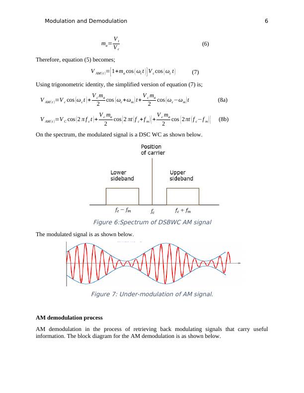
On the spectrum, the modulated signal is a DSC WC as shown below.
Figure 6:Spectrum of DSBWC AM signal
The modulated signal is as shown below.
Figure 7: Under-modulation of AM signal.
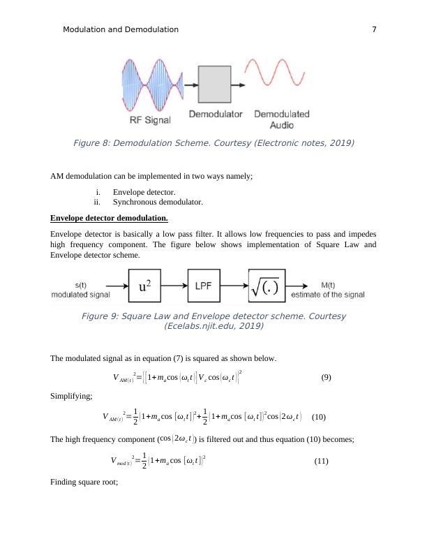
AM demodulation process
AM demodulation in the process of retrieving back modulating signals that carry useful
information. The block diagram for the AM demodulation is as shown below.
ma= V t
V c
(6)
Therefore, equation (5) becomes;
V AM (t )= [ 1+ma cos ( ωt t ) ] V c cos ( ωc t ) (7)
Using trigonometric identity, the simplified version of equation (7) is;
V AM (t )=V c cos ( ωc t ) + V c ma
2 cos ( ωc +ωm ) t+ V c ma
2 cos ( ωc−ωm ) t (8a)
V AM (t )=V C cos ( 2 π f c t ) + V c ma
2 cos {2 πt ( f c+ f m ) }+ V c ma
2 cos {2 πt ( f c−f m ) } (8b)
On the spectrum, the modulated signal is a DSC WC as shown below.
Figure 6:Spectrum of DSBWC AM signal
The modulated signal is as shown below.
Figure 7: Under-modulation of AM signal.
AM demodulation process
AM demodulation in the process of retrieving back modulating signals that carry useful
information. The block diagram for the AM demodulation is as shown below.
Modulation and Demodulation 7
Figure 8: Demodulation Scheme. Courtesy (Electronic notes, 2019)
AM demodulation can be implemented in two ways namely;
i. Envelope detector.
ii. Synchronous demodulator.
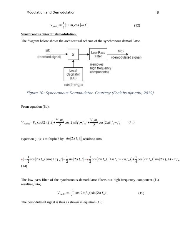
Envelope detector demodulation.
Envelope detector is basically a low pass filter. It allows low frequencies to pass and impedes
high frequency component. The figure below shows implementation of Square Law and
Envelope detector scheme.
Figure 9: Square Law and Envelope detector scheme. Courtesy
(Ecelabs.njit.edu, 2019)
The modulated signal as in equation (7) is squared as shown below.
V AM (t )
2= { [ 1+ ma cos ( ωt t ) ] V c cos ( ωc t ) }
2
(9)
Simplifying;
V AM (t )
2= 1
2 ( 1+ma cos [ωt t] )2+ 1
2 ( 1+ ma cos [ ωt t] ) 2 cos ( 2 ωc t ) (10)
The high frequency component (cos ( 2ωc t )) is filtered out and thus equation (10) becomes;
V mod (t )
2= 1
2 (1+ma cos [ωt t ] )2
(11)
Finding square root;
Figure 8: Demodulation Scheme. Courtesy (Electronic notes, 2019)
AM demodulation can be implemented in two ways namely;
i. Envelope detector.
ii. Synchronous demodulator.
Envelope detector demodulation.
Envelope detector is basically a low pass filter. It allows low frequencies to pass and impedes
high frequency component. The figure below shows implementation of Square Law and
Envelope detector scheme.
Figure 9: Square Law and Envelope detector scheme. Courtesy
(Ecelabs.njit.edu, 2019)
The modulated signal as in equation (7) is squared as shown below.
V AM (t )
2= { [ 1+ ma cos ( ωt t ) ] V c cos ( ωc t ) }
2
(9)
Simplifying;
V AM (t )
2= 1
2 ( 1+ma cos [ωt t] )2+ 1
2 ( 1+ ma cos [ ωt t] ) 2 cos ( 2 ωc t ) (10)
The high frequency component (cos ( 2ωc t )) is filtered out and thus equation (10) becomes;
V mod (t )
2= 1
2 (1+ma cos [ωt t ] )2
(11)
Finding square root;
Modulation and Demodulation 8
V mod (t )= 1
4 ( 1+ ma cos [ωt t ] ) (12)
Synchronous detector demodulation.
The diagram below shows the architectural scheme of the synchronous demodulator.
Figure 10: Synchronous Demodulator. Courtesy (Ecelabs.njit.edu, 2019)
From equation (8b);
V AM (t )=V C cos ( 2 π f c t ) + V c ma
2 cos {2 πt ( f c+ f m ) }+ V c ma
2 cos {2 πt ( f c−f m ) } (13)
Equation (13) is multiplied by { sin ( 2 π f c t ) } resulting into
¿ {− 1
2 cos ( 2 π f m t ) sin ( 2 π f m t )− 1
2 sin ( 2 π f c t ) −¿ 1
2 cos ( 2 π f mt ) ( 4 π f c t−2 π f m t ) + 1
4 cos ( 2 π f m t ) sin ( 2 π f c t +2 π f m t
(14)
The low pass filter of the synchronous demodulator filters out high frequency component (f c)
resulting into;
V mod (t )=−1
2 cos ( 2 π f m t ) sin ( 2 π f m t ) (15)
The demodulated signal is thus as shown in equation (15)
End of preview
Want to access all the pages? Upload your documents or become a member.
Related Documents
Design and Implementation of Communication System for Poor Quality Communication Channels using MATLABlg...
|5
|536
|270
Study Material on Aircraft: Instruments, Systems and Communicationlg...
|19
|4228
|494
Simulation of Digital Low Pass Filter and Amplitude Modulation-Demodulation in Matlab Simulink Environmentlg...
|15
|1944
|360
Wireless Networking: Components, Mixers, and Spread Spectrum Transmissionlg...
|19
|1586
|423
Telecommunicationlg...
|13
|2125
|139
Design of a Communication Link to Interconnect Two Locationslg...
|10
|2220
|189