Civil Engineering HNCB 43 Hydraulics Assignment Solution
VerifiedAdded on 2022/08/20
|9
|701
|14
Homework Assignment
AI Summary
This document presents a comprehensive solution to a hydraulics assignment designed for civil engineering students pursuing their HNCB qualification. The assignment addresses key concepts in fluid mechanics, including boundary layer analysis, pipe flow calculations, and the application of the Darcey-Weisbach equation. It explores practical scenarios such as determining pressure in a pipe supplying water to a city and designing a system to divert water flow. The solution encompasses detailed calculations, the use of relevant formulas, and considerations for optimizing fluid distribution within pipes and open channels. The assignment also includes a list of references for further study and research. The assignment is structured around several tasks that require the application of physics principles to solve hydrostatic and hydrodynamic problems. The student is tasked to calculate forces related to fluids at rest and in motion, and to develop solutions for the distribution of fluids within pipes, and calculate the hydrostatic pressure exerted on substructures.
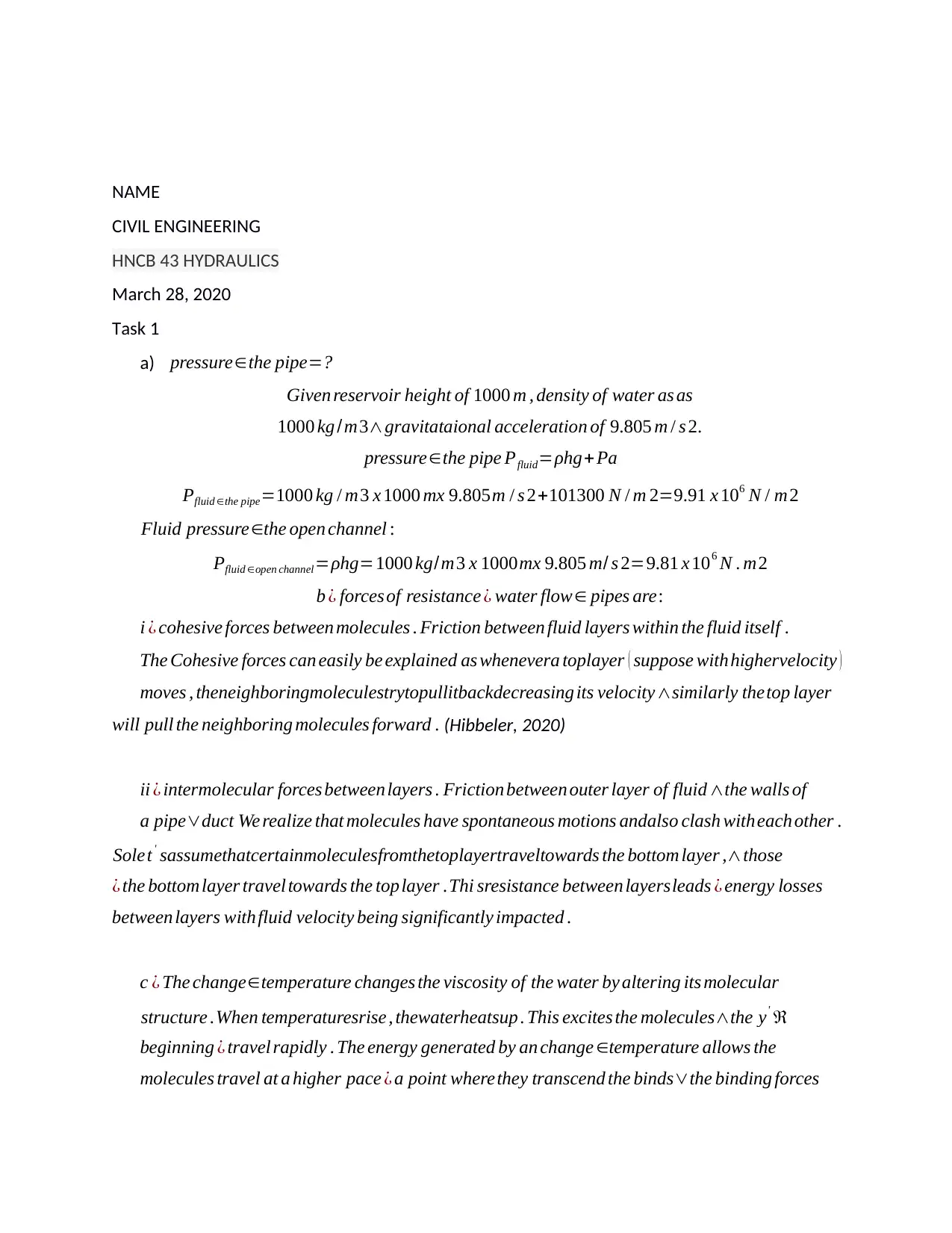
NAME
CIVIL ENGINEERING
HNCB 43 HYDRAULICS
March 28, 2020
Task 1
a) pressure∈the pipe=?
Given reservoir height of 1000 m , density of water as as
1000 kg /m3∧gravitataional acceleration of 9.805 m / s 2.
pressure∈the pipe Pfluid=ρhg+ Pa
Pfluid ∈the pipe=1000 kg / m3 x 1000 mx 9.805m / s 2+101300 N / m 2=9.91 x 10⁶ N / m2
Fluid pressure∈the open channel :
Pfluid ∈open channel=ρhg=1000 kg/m3 x 1000mx 9.805 m/ s 2=9.81 x 10⁶ N . m2
b ¿ forces of resistance ¿ water flow∈ pipes are:
i ¿ cohesive forces between molecules . Friction between fluid layers within the fluid itself .
The Cohesive forces can easily be explained as whenevera toplayer ( suppose withhighervelocity )
moves , theneighboringmoleculestrytopullitbackdecreasing its velocity∧similarly thetop layer
will pull the neighboring molecules forward . (Hibbeler, 2020)
ii ¿ intermolecular forces between layers . Friction between outer layer of fluid ∧the walls of
a pipe∨duct We realize that molecules have spontaneous motions andalso clash witheach other .
Solet' sassumethatcertainmoleculesfromthetoplayertraveltowards the bottom layer ,∧those
¿ the bottom layer travel towards the toplayer .Thi sresistance between layersleads ¿ energy losses
between layers withfluid velocity being significantly impacted .
c ¿ The change∈temperature changes the viscosity of the water by altering its molecular
structure .When temperaturesrise , thewaterheatsup . This excites the molecules∧the y' ℜ
beginning ¿ travel rapidly . The energy generated by an change ∈temperature allows the
molecules travel at a higher pace ¿ a point wherethey transcend the binds∨the binding forces
Paraphrase This Document
Need a fresh take? Get an instant paraphrase of this document with our AI Paraphraser
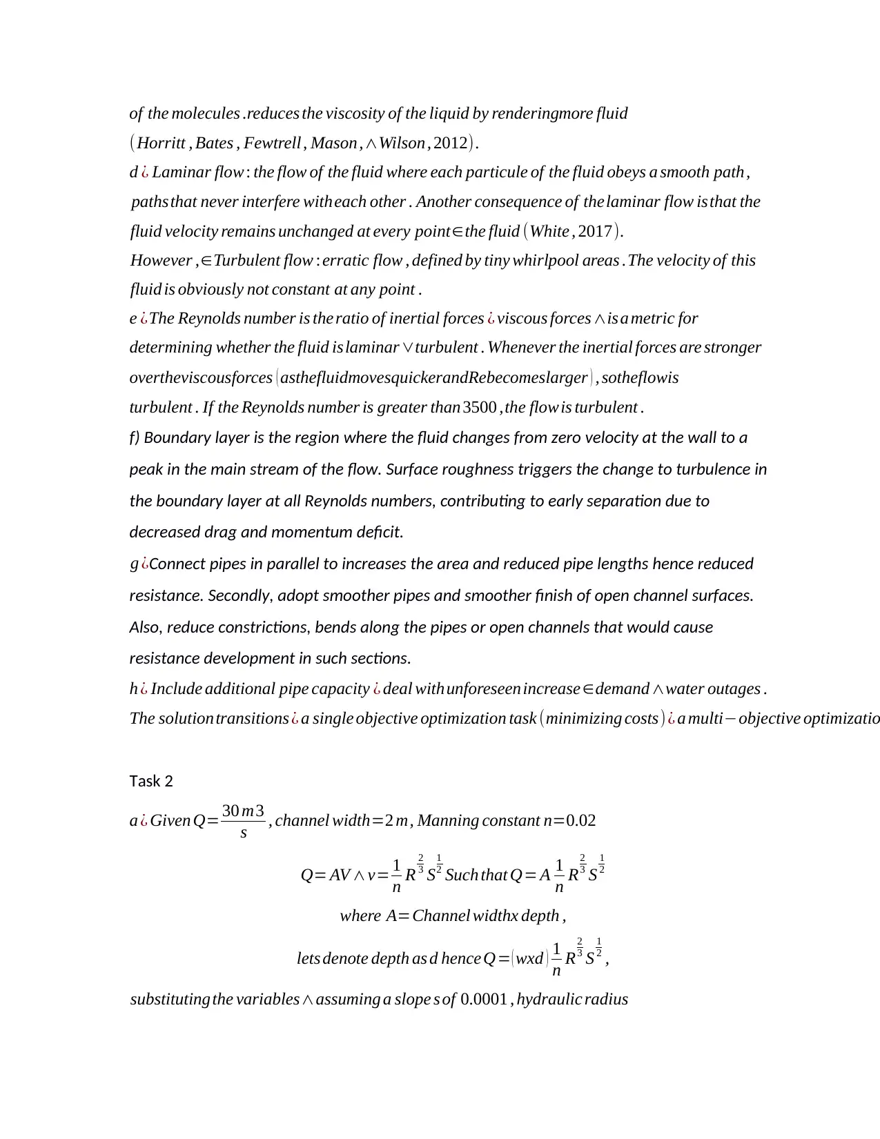
of the molecules .reduces the viscosity of the liquid by renderingmore fluid
(Horritt , Bates , Fewtrell , Mason,∧Wilson, 2012).
d ¿ Laminar flow : the flow of the fluid where each particule of the fluid obeys a smooth path,
pathsthat never interfere witheach other . Another consequence of thelaminar flow isthat the
fluid velocity remains unchanged at every point∈the fluid (White , 2017).
However ,∈Turbulent flow :erratic flow , defined by tiny whirlpool areas .The velocity of this
fluid is obviously not constant at any point .
e ¿The Reynolds number is theratio of inertial forces ¿ viscous forces∧isa metric for
determining whether the fluid islaminar∨turbulent . Whenever the inertial forces are stronger
overtheviscousforces ( asthefluidmovesquickerandRebecomeslarger ) , sotheflowis
turbulent . If the Reynolds number is greater than 3500 ,the flow is turbulent .
f) Boundary layer is the region where the fluid changes from zero velocity at the wall to a
peak in the main stream of the flow. Surface roughness triggers the change to turbulence in
the boundary layer at all Reynolds numbers, contributing to early separation due to
decreased drag and momentum deficit.
g ¿Connect pipes in parallel to increases the area and reduced pipe lengths hence reduced
resistance. Secondly, adopt smoother pipes and smoother finish of open channel surfaces.
Also, reduce constrictions, bends along the pipes or open channels that would cause
resistance development in such sections.
h ¿ Include additional pipe capacity ¿ deal withunforeseen increase∈demand∧water outages .
The solutiontransitions ¿ a single objective optimization task (minimizing costs)¿ a multi−objective optimizatio
Task 2
a ¿ Given Q= 30 m3
s , channel width=2 m, Manning constant n=0.02
Q= AV ∧v= 1
n R
2
3 S
1
2 Such that Q= A 1
n R
2
3 S
1
2
where A=Channel widthx depth ,
lets denote depth as d hence Q= ( wxd ) 1
n R
2
3 S
1
2 ,
substituting the variables∧assuming a slope s of 0.0001 , hydraulic radius
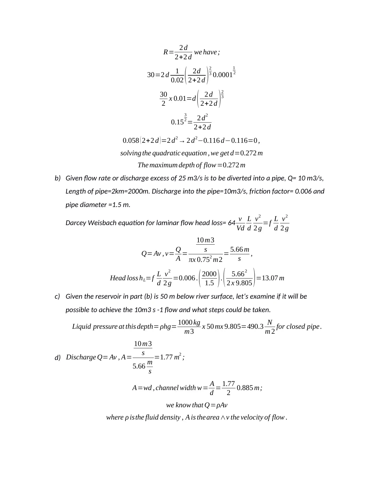
R= 2 d
2+2 d we have ;
30=2 d 1
0.02 ( 2d
2+2 d )2
3 0.0001
1
2
30
2 x 0.01=d ( 2 d
2+2 d ) 2
3
0.15
3
2 = 2 d2
2+2 d
0.058 ( 2+2 d )=2 d2 → 2 d2−0.116 d−0.116=0 ,
solving the quadratic equation , we get d=0.272 m
The maximum depth of flow=0.272 m
b) Given flow rate or discharge excess of 25 m3/s is to be diverted into a pipe, Q= 10 m3/s,
Length of pipe=2km=2000m. Discharge into the pipe=10m3/s, friction factor= 0.006 and
pipe diameter =1.5 m.
Darcey Weisbach equation for laminar flow head loss= 64 v
Vd
L
d
v2
2 g =f L
d
v2
2 g
Q= Av , v= Q
A =
10 m3
s
πx 0.752 m2 = 5.66 m
s ,
Head loss hL=f L
d
v2
2 g =0.006 . ( 2000
1.5 ) . ( 5.662
2 x 9.805 ) =13.07 m
c) Given the reservoir in part (b) is 50 m below river surface, let’s examine if it will be
possible to achieve the 10m3 s -1 flow and what steps could be taken.
Liquid pressure at this depth= ρhg= 1000 kg
m3 x 50 mx 9.805=490.3 N
m 2 for closed pipe.
d) Discharge Q= Av , A=
10 m3
s
5.66 m
s
=1.77 m2 ;
A=wd , channel width w= A
d = 1.77
2 0.885 m;
we know that Q=ρAv
where ρ isthe fluid density , A is thearea∧v the velocity of flow .
⊘ This is a preview!⊘
Do you want full access?
Subscribe today to unlock all pages.

Trusted by 1+ million students worldwide
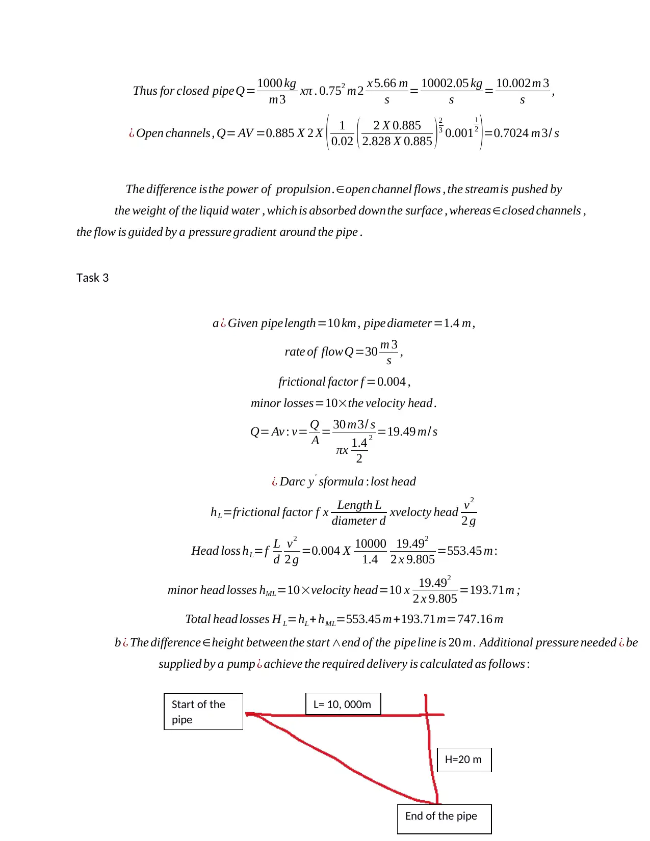
Thus for closed pipeQ=1000 kg
m3 xπ . 0.752 m2 x 5.66 m
s = 10002.05 kg
s = 10.002m 3
s ,
¿ Open channels, Q= AV =0.885 X 2 X ( 1
0.02 ( 2 X 0.885
2.828 X 0.885 )2
3 0.001
1
2
)=0.7024 m3/ s
The difference isthe power of propulsion.∈open channel flows , the streamis pushed by
the weight of the liquid water , which is absorbed downthe surface , whereas∈closed channels ,
the flow is guided by a pressure gradient around the pipe .
Task 3
a ¿ Given pipelength=10 km, pipe diameter=1.4 m,
rate of flowQ=30 m 3
s ,
frictional factor f =0.004 ,
minor losses=10×the velocity head .
Q= Av : v= Q
A = 30 m3/ s
πx 1.4
2
2 =19.49 m/s
¿ Darc y' sformula :lost head
hL=frictional factor f x Length L
diameter d xvelocty head v2
2 g
Head loss hL=f L
d
v2
2 g =0.004 X 10000
1.4
19.492
2 x 9.805 =553.45 m:
minor head losses hML=10×velocity head=10 x 19.492
2 x 9.805 =193.71m ;
Total head losses H L=hL+ hML=553.45 m+193.71m=747.16 m
b ¿ The difference ∈height between the start ∧end of the pipeline is 20 m. Additional pressure needed ¿ be
supplied by a pump ¿ achieve the required delivery is calculated as follows :
H=20 m
L= 10, 000mStart of the
pipe
End of the pipe
Paraphrase This Document
Need a fresh take? Get an instant paraphrase of this document with our AI Paraphraser
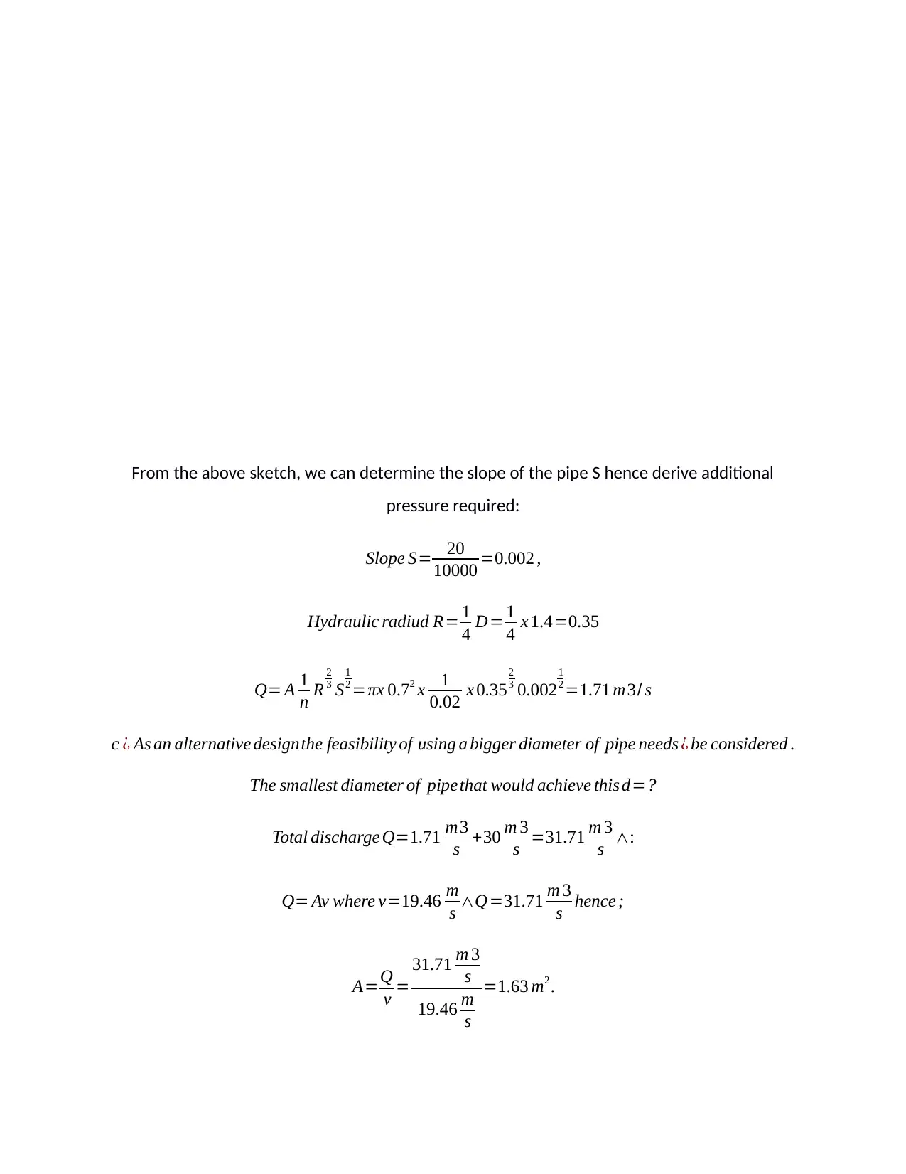
From the above sketch, we can determine the slope of the pipe S hence derive additional
pressure required:
Slope S= 20
10000 =0.002 ,
Hydraulic radiud R= 1
4 D= 1
4 x 1.4=0.35
Q= A 1
n R
2
3 S
1
2 =πx 0.72 x 1
0.02 x 0.35
2
3 0.002
1
2 =1.71 m3/ s
c ¿ As an alternative designthe feasibility of using a bigger diameter of pipe needs ¿ be considered .
The smallest diameter of pipethat would achieve this d=?
Total discharge Q=1.71 m3
s +30 m 3
s =31.71 m 3
s ∧:
Q= Av where v=19.46 m
s ∧Q=31.71 m 3
s hence ;
A=Q
v =
31.71 m 3
s
19.46 m
s
=1.63 m2 .
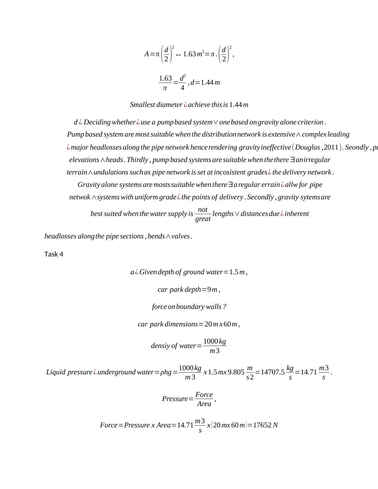
A=π ( d
2 )
2
↔ 1.63 m2=π . ( d
2 )
2
,
1.63
π = d2
4 , d=1.44 m
Smallest diameter ¿ achieve this is 1.44 m
d ¿ Deciding whether ¿ use a pumpbased system∨one based on gravity alone criterion .
Pump based system are most suitable when the distribution network is extensive∧complex leading
¿ major headlosses along the pipe network hence rendering gravity ineffective(Douglas ,2011). Seondly , pu
elevations∧heads . Thirdly , pump based systems are suitable when thethere ∃anirregular
terrain∧undulations such as pipe network is set at incosistent grades¿ the delivery network .
Gravity alone systems are mosts suitable when there ∃a regular errain ¿ allw for pipe
netwok ∧systems with uniform grade ¿ the points of delivery . Secondly , gravity sytemsare
best suited when the water supply is not
great lengths∨distances due ¿ inherent
headlosses alongthe pipe sections , bends∧valves .
Task 4
a ¿ Given depth of ground water=1.5 m ,
car park depth=9 m ,
force on boundary walls ?
car park dimensions=20 m x 60 m ,
densiy of water= 1000 kg
m3
Liquid pressure ¿ underground water=ρhg=1000 kg
m 3 x 1.5 mx 9.805 m
s 2 =14707.5 kg
s =14.71 m3
s .
Pressure= Force
Area ,
Force=Pressure x Area=14.71 m3
s x ( 20 mx 60 m )=17652 N
2 )
2
↔ 1.63 m2=π . ( d
2 )
2
,
1.63
π = d2
4 , d=1.44 m
Smallest diameter ¿ achieve this is 1.44 m
d ¿ Deciding whether ¿ use a pumpbased system∨one based on gravity alone criterion .
Pump based system are most suitable when the distribution network is extensive∧complex leading
¿ major headlosses along the pipe network hence rendering gravity ineffective(Douglas ,2011). Seondly , pu
elevations∧heads . Thirdly , pump based systems are suitable when thethere ∃anirregular
terrain∧undulations such as pipe network is set at incosistent grades¿ the delivery network .
Gravity alone systems are mosts suitable when there ∃a regular errain ¿ allw for pipe
netwok ∧systems with uniform grade ¿ the points of delivery . Secondly , gravity sytemsare
best suited when the water supply is not
great lengths∨distances due ¿ inherent
headlosses alongthe pipe sections , bends∧valves .
Task 4
a ¿ Given depth of ground water=1.5 m ,
car park depth=9 m ,
force on boundary walls ?
car park dimensions=20 m x 60 m ,
densiy of water= 1000 kg
m3
Liquid pressure ¿ underground water=ρhg=1000 kg
m 3 x 1.5 mx 9.805 m
s 2 =14707.5 kg
s =14.71 m3
s .
Pressure= Force
Area ,
Force=Pressure x Area=14.71 m3
s x ( 20 mx 60 m )=17652 N
⊘ This is a preview!⊘
Do you want full access?
Subscribe today to unlock all pages.

Trusted by 1+ million students worldwide
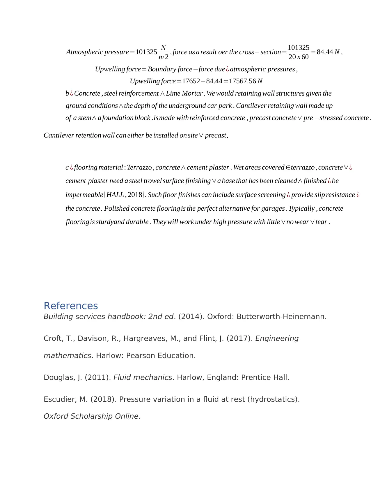
Atmospheric pressure=101325 N
m 2 , force as a result oer the cross−section=101325
20 x 60 =84.44 N ,
Upwelling force=Boundary force−force due ¿ atmospheric pressures ,
Upwelling force=17652−84.44=17567.56 N
b ¿ Concrete , steel reinforcement ∧Lime Mortar . We would retaining wall structures given the
ground conditions∧the depth of the underground car park . Cantilever retaining wall made up
of a stem∧a foundation block .ismade withreinforced concrete , precast concrete∨ pre−stressed concrete .
Cantilever retention wall can either be installed on site∨ precast.
c ¿ flooring material : Terrazzo , concrete∧cement plaster . Wet areas covered ∈terrazzo , concrete∨¿
cement plaster need a steel trowel surface finishing∨a base that has been cleaned∧finished ¿ be
impermeable ( HALL , 2018 ) . Such floor finishes can include surface screening ¿ provide slip resistance ¿
the concrete . Polished concrete flooring is the perfect alternative for garages. Typically , concrete
flooring is sturdyand durable . They will work under high pressure with little∨no wear∨tear .
References
Building services handbook: 2nd ed. (2014). Oxford: Butterworth-Heinemann.
Croft, T., Davison, R., Hargreaves, M., and Flint, J. (2017). Engineering
mathematics. Harlow: Pearson Education.
Douglas, J. (2011). Fluid mechanics. Harlow, England: Prentice Hall.
Escudier, M. (2018). Pressure variation in a fluid at rest (hydrostatics).
Oxford Scholarship Online.
Paraphrase This Document
Need a fresh take? Get an instant paraphrase of this document with our AI Paraphraser
Falkovich, G. (2018). Fluid mechanics. Cambridge, United Kingdom:
Cambridge University Press.
Fox, R.W. (2016). Fluid mechanics. Hoboken, NJ: Wiley.
HALL, F. (2018). BUILDING SERVICES HANDBOOK. S.l.: ROUTLEDGE.
Hall, F. and Greeno, R. (2013). Building services handbook: incorporating
current building & water regulations. Oxon, Ox: Routledge.
Hibbeler, R.C. (2020). Fluid mechanics. Harlow, Essex: Pearson Education
Limited.
Horritt, M., Bates, P., Fewtrell, T., Mason, D., and Wilson, M. (2012). Modelling
the hydraulics of the Carlisle 2005 flood event. Proceedings of the Institution
of Civil Engineers - Water Management, 163 (6), 273–281.
Hydraulics for civil engineers: Shock transmission units in construction.
(2013). London: ICE.
Keaton, J. (2018). Manning Formula. Encyclopedia of Earth Sciences Series
Encyclopedia of Engineering Geology, 595–595.
Landau, L. and Lifshit︠ s︡ E. (2012). Fluid mechanics. Amsterdam: Elsevier
Butterworth-Heinemann.
Massey, B. and Ward-Smith, A. (2018). Mechanics of fluids. Place of
publication not identified: CRC Press.
Rančić M . and Silvestrov, S. (2016). Engineering mathematics. Cham,
Switzerland: Springer.
Shames, I. (2015). Mechanics of fluids. New York: McGraw-Hill.
Stroud, K. and Booth, D. (2013). Engineering mathematics. South Norwalk,
CT: Industrial Press, Inc.
White, F. and Chul, R. (2016). Fluid mechanics. New York: McGraw-Hill
education.
White, F. (2017). Fluid mechanics. New Delhi, India: McGraw-Hill Education
(India).
Wynn, P. (2014). Hydraulics for civil engineers. London: ICE Publishing.
⊘ This is a preview!⊘
Do you want full access?
Subscribe today to unlock all pages.

Trusted by 1+ million students worldwide
1 out of 9
Your All-in-One AI-Powered Toolkit for Academic Success.
+13062052269
info@desklib.com
Available 24*7 on WhatsApp / Email
![[object Object]](/_next/static/media/star-bottom.7253800d.svg)
Unlock your academic potential
Copyright © 2020–2026 A2Z Services. All Rights Reserved. Developed and managed by ZUCOL.